Note: Descriptions are shown in the official language in which they were submitted.
CA 02979603 2017-09-13
WO 2016/146776 PCT/EP2016/055864
- 1 -
A SHUT-OFF VALVE
BACKGROUND OF THE INVENTION
The present invention relates to a shut-off valve, in
particular a shut-off valve for use on a cylinder containing
pressurised fluid.
Although reference is made to a "cylinder", it will be
understood that the invention is applicable broadly to all
portable pressurised gas containers whether they are
strictly in the form of a cylinder or not.
Such cylinders are used to supply gas for a range of
applications including welding and cutting hoses and
torches, gas packaging machines and laboratory equipment.
There currently exist valves for use on cylinders containing
pressurised fluid which can close a cylinder under certain
prescribed or predetermined conditions. An example of such a
valve is disclosed in US 6,328,053, which comprises a valve
which will close automatically on detection of a leak
therein.
SUMMARY OF THE INVENTION
According to a first aspect of the present invention, there
is provided a system comprising a plurality of a shut-off
valve for use on a cylinder containing pressurised fluid,
each shut-off valve comprising:
a valve element movable between an open position and a
closed position;
a controller; and
a wireless signal receiver;
CA 02979603 2017-09-13
WO 2016/146776
PCT/EP2016/055864
-2-
wherein the controller is operable to move the valve
element from the open position to the closed position in
response to a wireless signal that is received by the
wireless signal receiver;
wherein the system further comprises a control panel
remotely located from the plurality of the shut-off valves
and comprising a signal emitter, wherein the control panel
is actuatable for sending the signal, via the signal
emitter, to the shut-off valves.
The controller may, for example, comprise a valve actuator
such as a solenoid or motor for moving the valve member.
The control panel may be acutatable by a push button. This
push button may be for instance, an emergency stop button,
located for instance on a wall of a facility containing the
shut-off valves.
The control panel may be acutatable based on a signal from
at least one of a fire alarm and/or a smoke alarm so that
the cylinders can be shut in the case of fire.
The control panel may be acutatable based on a time switch
so that the cylinders can be shut at the end of a working
day.
The control panel may comprise a microphone, and be
acutatable based on a predetermined audio command received
by the microphone (for example, a voice command). In this
way, the shut-off valves can be conveniently actuated by
voice or by some other audio command.
CA 02979603 2017-09-13
WO 2016/146776 PCT/EP2016/055864
-3-
According to a second aspect of the present invention, there
is provided a shut-off valve for use on a cylinder
containing pressurised fluid, the shut-off valve comprising:
a valve element movable between an open position and a
closed position;
a controller;
a sensor for measuring a parameter; and
wherein the controller is operable to move the valve
element from the open position to the closed position in
response to a predetermined signal from the sensor; wherein
=
a) the sensor is a thermometer for measuring the
temperature of the valve's surroundings, and the
predetermined signal is generated in response to the
temperature recorded by the thermometer being outside a
predetermined range;
b) the sensor is a pressure gauge for measuring the
pressure of the valve's surroundings, and the predetermined
signal is generated in response to the pressure recorded by
the pressure gauge being outside a predetermined range;
c) the sensor is a microphone, and the predetermined
signal is generated in response to a predetermined audio
command received by the microphone; or
d) the sensor is a gas detector for monitoring levels of
one or more type of gas (for example, oxygen and/or toxic or
hazardous gases, such as chlorine).
In some embodiments, multiple sensors are provided such a
valve may include the sensors from one or more of a) to d)
above.
The above sensors provide a valve which can automatically
open and close depending on its surroundings.
CA 02979603 2017-09-13
WO 2016/146776
PCT/EP2016/055864
-4-
According to a third aspect of the present invention, there
is provided a shut-off valve for use on a cylinder
containing pressurised fluid, the shut-off valve comprising:
a valve element movable between an open position and a
closed position;
a controller;
a sensor electronically connected to the controller for
measuring a parameter; and
a locking means operable to allow the valve element to
move from the closed position to the open position only in
response to a predetermined signal from the sensor.
In this case, the sensor may comprise a fingerprint reader
and the parameter may be a fingerprint.
In another embodiment, the sensor may comprise an RFID tag
reader and the parameter may be a signal from an RFID tag.
The output from the sensor may be monitored by a data logger
located on the valve.
The controller from a valve according the either the second
or third aspects of the invention may be further operable to
move the valve element from the open position to the closed
position in response to a wireless signal that is received
by a wireless signal receiver located on the shut-off valve.
In this way, the valve is useable in a system described in
relation to the first aspect of the invention.
In a fourth aspect of the invention, the or each shut-off
valve from the first, second, and third aspects of the
CA 02979603 2017-09-13
WO 2016/146776
PCT/EP2016/055864
- 5 -
invent i on may each be connected to a cylinder for
pressurised fluid.
CA 02979603 2017-09-13
WO 2016/146776 PCT/EP2016/055864
- 6 -
BRIEF DESCRIPTION OF THE FIGURES
The present invention will now be described with reference
to the accompanying Figure 1 which shows a schematic of the
present invention.
DETAILED DESCRIPTION
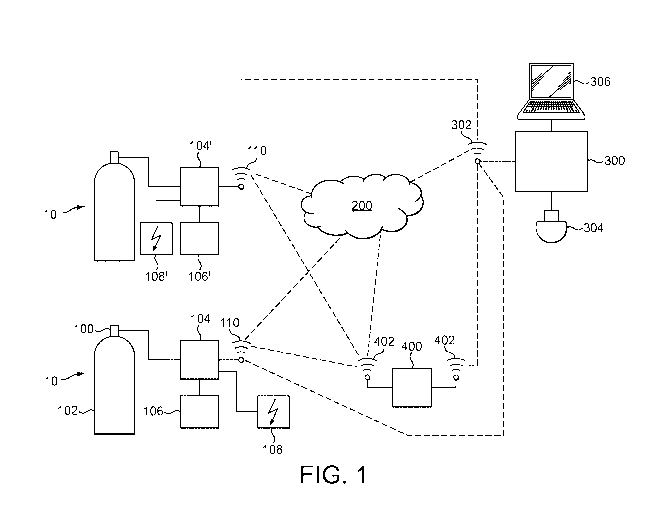
With reference to Figure 1, there is shown an assembly 10
comprising a valve 100 connectable to a cylinder body 102
for a pressurised fluid. The valve comprises a valve element
movable between an open position in which fluid can escape
the cylinder, and a closed position in which the fluid is
contained within the cylinder.
Electrically connected to the valve 100 are a CPU 104 and a
sensor 106 for monitoring a parameter of either the valve,
fluid in fluid communication with the valve, a fluid in the
cylinder, and/or the environment around the cylinder 102.
The parameter monitored by the sensor 106 may be, for
instance, the duration that the valve element is open, the
quantity of fluid flowing through the valve, leakage from
the valve, ambient temperature and/or pressure around the
cylinder, and/or the number of opening cycles the valve
element makes. The sensor 106 may alternatively be a
microphone. The CPU 104 and sensor 106 may be powered by any
appropriate power source 108. Dependent on the value of the
parameter measure by the sensor 106, signals from the sensor
106 may be transmitted via the CPU 104 to control the
operation of the valve element.
The valve assembly 10 also comprises a wireless signal
receiver 110 for receiving an electronic signal from a
remote location as will be described. The wireless signal
CA 02979603 2017-09-13
WO 2016/146776 PCT/EP2016/055864
-7-
receiver can be configured to receive signals over any
conventional wireless transmission method, for instance
Bluetooth, UHF and GSM. The wireless receiver 508 could
additionally allow for non-wireless communication signals to
be received, for instance by being provided with a USB port.
Each receiver could alternatively be a transceiver to allow
signals to be emitted, as well as received, from the valve
assembly 10.
A control panel 300 is located in a location remote from the
valve assembly 10. The control panel 300 is connected to a
wireless signal emitter 302 (which alternatively may be a
transceiver), and may be connected to an input device 304
and/or a computer network 306.
A relay station 400 may be provided to relay signals between
the valve 100 and the control panel 300. The relay station
comprises at least one wireless transceiver for
communicating signals to and from the valve 100 and the
control panel 300.
Signals between the control panel 300, the relay station
400, and the valve 100 may be communicated and/or stored in
the cloud 200.
The purpose of the control panel 300 is to allow remote
operation of the valve assembly 10 and any other valve
assembly (for instance valve assembly 10' as shown in Figure
1) that the control panel 300 can send a wireless signal to.
In one embodiment, a wireless signal may be sent from the
control panel 300 to some or all of the valve assemblies
CA 02979603 2017-09-13
WO 2016/146776 PCT/EP2016/055864
-8-
10;10' which instructs the valve 100;100' of these
assemblies to close.
The wireless signal from the control panel 300 is
transmitted via the emitter 302 to each of the valve
assemblies 10;10' either directly, via the cloud 200, or via
the relay station 400.
Sending of the wireless signal may be triggered by
depression of the input device 304, which may be for
instance an emergency stop button. Such an input device 304
may be provided in addition to a further, separate
controller for controlling the normal operation of the valve
100 (i.e., non-emergency use).
For example, each valve 100 of a plurality of valves 100 may
be provided with a first controller, whilst a single input
device 304 may be provided for emergency shut off of all of
the plurality of valves 100.
The signal may alternatively be triggered by a fire alarm
going off, or a smoke detector triggering. The signal may
also be triggered based on a command from the computer
network 306 which is connected to the control panel 300.
Another situation in which the signal may be triggered might
be when the facility containing the valve assemblies 10'10'
is shut for the day. In this case, it may be desirable to
send a signal via the control panel 300 to the valve
assemblies located within the facility to ensure that none
of them have accidently been left open. For this purpose,
the control panel 300 may comprise a time switch that
provides a signal indicating a predetermined time so that
CA 02979603 2017-09-13
WO 2016/146776 PCT/EP2016/055864
-9-
the control panel can be triggered to transmit the signal at
the predetermined time.
The signal may alternatively be triggered in response to a
voice command from an operator next to the control panel, or
in response to a measured parameter of the conditions
surrounding one/all of the valves. This measured condition
may be the temperature around the monitored valve(s); the
pressure around the monitored valve(s); and/or the chemical
composition of the environment around the monitored
valve(s).
It will be appreciated that modifications could be made to
the assembly 10 described above without departing from the
scope of the invention.
In one embodiment the sensor 106 may communicate with the
CPU 104 and the valve 100 and serve as a mechanism which
keeps the valve closed to personnel who are not authorized
to use the valve. Such embodiments have particular
application in the medical field in which it is very
important to restrict access to certain fluids such that
only qualified/authorised individuals can use these.
A shut-off valve in accordance with such an embodiment may
comprise a sensor 106 that is electronically arranged to
provide the authorisation signal to the CPU 104 and to sense
data that can be used to authenticate a user. The controller
104 may be arranged to allow the valve element to move from
the closed position to the open position only if the
authorisation signal indicates that the user is
authenticated.
CA 02979603 2017-09-13
WO 2016/146776 PCT/EP2016/055864
- 10 -
The sensor 106 may be an RFID or NFC tag reader such that
the valve 100 can only be operated if a particular RFID or
NFC tag (supplied to an authorized person) is within the
vicinity of the RFID or NFC tag reader. In this way, the
sensor would only output a signal indicating that a user is
authenticated when the correct RFID or NFC tag is nearby.
Optionally, the presence of the tag may trigger the
controller 104 to allow the valve element to move from the
closed position to the open position for a predetermined
period of time, following which the controller will move the
valve element from the open position to the closed position.
The tag may be presented to the device again when that time
period has expired to again authenticate the user.
Alternatively, the presence of the tag may trigger the
controller 104 to allow the valve element to move from the
closed position to the open position until a predetermined
quantity of fluid has been dispensed from the cylinder,
following which the controller will move the valve element
from the open position to the closed position. The tag may
be presented to the device again when that quantity has been
dispensed to again authenticate the user.
In a preferred version of this embodiment, the RFID or NFC
tag can be used as a payment device, such that the user
makes a payment each time the device authenticates the user.
In this way, a user can pay for the provision of stored
fluid.
The sensor 106 could alternatively be a biometric reader,
for instance a fingerprint scanner, responsive to a
biometric from an authorized person. In this way, the sensor
CA 02979603 2017-09-13
WO 2016/146776 PCT/EP2016/055864
-11-
would only output a signal indicating that a user is
authenticated when the correct fingerprint is presented.
The sensor 106 may comprise a socket and be arranged to
sense the insertion of an electronic key therein. In this
way, the sensor would only output a signal indicating that a
user is authenticated when the correct electronic key is
inserted.
An indication means, for instance in the form of a visual
display or a speaker, may be electronically connected to the
CPU 104 on the valve. The indication means would be operable
to emit a first indication upon an authorized person being
allowed access to the valve, and a different indication in
response to an access attempt from an unathorized person.
The sensor could alternatively be used to sense the position
of a component of a mechanical lock. In this way, the sensor
would only output a signal indicating that a user is
authenticated when the mechanical lock has been unlocked.
A data logger may be electronically connected to the CPU 104
for monitoring which authorized and/or unauthorized
personnel operate the valve, and when. Data from the logger
may be stored in a memory, or may be sent by a wireless
transceiver 110 on the valve to a remote location, for
instance the control panel 300 or the cloud 200.