Note: Descriptions are shown in the official language in which they were submitted.
TENSION-SET TIEBACK PACKER
CROSS-REFERENCE TO RELATED APPLICATIONS
[0001] This application is co-pending with U.S. Appl. 14/693,076, filed 22-
APR-2015 and
entitled "Tension-Set Tieback Packer".
BACKGROUND OF THE DISCLOSURE
[0002] A liner top packer is run as a part of a liner-hanger assembly to
create a reliable
liner-top seal between the host casing and the liner string. Additionally, the
liner top
packer can isolate formation pressures below the liner top from the casing
above, can
isolate treating pressures or acid work below the liner top from the casing,
can isolate
fluids while cement sets, can mitigate gas migration, and can isolate lost
circulation zones.
The liner top packer can also be used as a tieback completion or production
packer.
Therefore, the liner top packer serves a number of important and useful
purposes.
[0003] In current techniques, hydraulics are used to set a liner top
packer. For example, a
liner top packer 30 as shown in Fig. 1A is hydraulically set in casing 10 with
a hydraulic
setting tool 20. The setting tool 20 has a bushing 22 disposed on a splined
shaft 24 and
threaded to a lock sub 31 of the packer 30. The setting tool 20 also includes
hydraulic
pistons 26 and a setting sleeve 28. The packer 30 includes a mandrel 32
coupled to the
lock sub 31. Opposing slips 34 and cones 36 are disposed on the mandrel 32 on
either side
of a packing element 38.
[0004] During setting operations, the setting tool 20 is coupled by the
bushing 22 to the
lock sub 31 and the packer's mandrel 32 to run the packer 30 in the casing 10.
When
setting depth is reached, hydraulic pressure communicated in the setting tool
20 actuates
the pistons 26, which pushes the setting sleeve 28 downward to compress the
slips 34, the
cones 36, and the packing element 38 and to set the packer 30. To build up
pressure, a sub
23 threaded into the splined shaft 24 accepts a ball, which seals off the
tubing to build
1
CA 2979893 2019-02-07
pressure in the pistons 26. Rotation of the setting tool 20 then unthreads the
bushing 22
from the lock sub 31 so the tool 20 can be retrieved.
[0005] As an alternative to the use of hydraulics, current techniques run
and mechanically
set a separate liner hanger below a liner top packer so a compression setting
tool can then
be used to set a liner top packer. For example, a liner top packer 30 as shown
in Fig. 1B is
coupled uphole of a separate liner hanger 35. The packer 30 has a packing
element 38
disposed on the mandrel 32. The liner hanger 35 has slips 37a that are moved
against
cones 37b using a J-slot mechanism 39.
[0006] The packer 30 and liner hanger 35 are run in hole with the setting
tool 20. When
setting depth is reached, the liner hanger 35 is set in the casing 10 by
operating the J-slot
mechanism 39 and wedging the slips 37a with the cones 37b against the casing
10. At this
point, rotation of the setting tool 20 unthreads the bushing 22 from the lock
sub 31. The
setting tool 20 is then lifted uphole inside the surrounding setting sleeve 28
until dogs 25
on the tool 20 bias outward beyond the distal end of the sleeve 28. Downhole
movement of
the setting tool 20 then engages the dogs 25 against the sleeve 28 so the
sleeve 28 can be
pushed against the packing element 38 on the packer 30 to set it against the
casing 10. The
setting tool 20 can then be removed.
[0007] Although these current techniques are successful, they may not be
suitable for
some implementations. For instance, using hydraulics downhole may be
undesirable in
implementations that have equipment that is pressure activated. Also, using a
separate
liner hanger adds additional cost to the assembly, which may be undesirable.
These and
other reasons may make alternative techniques more favorable for setting a
liner top
packer.
[0008] The subject matter of the present disclosure is directed to
overcoming, or at least
reducing the effects of, one or more of the problems set forth above.
SUMMARY OF THE DISCLOSURE
[0009] According to the present disclosure, an apparatus for supporting
tubing, such as a
liner, in casing of a borehole includes a packer and a setting tool. The
packer can be a liner
2
CA 2979893 2017-09-22
top packer. The packer has a housing and a packing element. The housing
defines a bore
and is coupled to the tubing extending downhole therefrom. The packing element
is
disposed on the housing and is settable from an unpacked state to a packed
state in the
casing. For example, the packing element can include at least one packing
slip, at least one
packing cone, and at least one compressible element, which are disposed on the
housing
adjacent one another and are movable against one another to set in the casing.
[0010] The setting tool for setting the packer is retrievable after
setting. The setting tool
has an inner mandrel and an outer mandrel. The outer mandrel has at least one
setting slip
being movable from a retracted state away from the casing to an extended state
toward the
casing. Additionally, the outer mandrel has a first rotatable connection to
the inner
mandrel and initially holds the at least one setting slip in the retracted
state. For its part,
the inner mandrel has a second rotatable connection to the housing of the
packer.
[0011] The inner mandrel rotated with first rotation relative to the outer
mandrel
releases the first rotatable connection (between the inner and outer
mandrels). This
permits extension of the at least one setting slip on the outer mandrel for
setting in the
extended state in the casing. The inner mandrel moved after the first rotation
with first
movement relative to the outer mandrel pulls the housing against a portion of
the outer
mandrel. This pulling compresses the packing element to the packed state in
the casing.
[0012] The inner mandrel rotated with second rotation relative to the outer
mandrel then
releases the second rotatable connection (of the inner mandrel) to the
housing. This
permits retrieval of the setting tool from the packer. For instance, the inner
mandrel
moved after the second rotation with second movement releases the at least one
setting
slip from the extended state toward the retracted state.
[0013] The first and second rotations discussed above can be in opposite
directions.
Although less desirable, it is possible to have the first and second rotations
be made in the
same direction. In this case, a first number of turns for the first rotation
to release can be
less than the second number of turns in the same direction for the second
rotation. The
first rotatable connection can include bayonets engaged between the outer
mandrel and
the inner mandrel. Alternatively, the first rotatable connection can use a
course thread.
3
CA 2979893 2017-09-22
The second rotatable connection can include a nut disposed on a splined shaft
of the inner
mandrel and threaded to an internal thread in the bore of the housing.
[0014] Between the first and second rotatable connections, the setting tool
can have a
swivel. With the first rotation of the inner mandrel (to release the first
rotatable
connection), the swivel clutches so that the first rotation is not transferred
to the second
rotatable connection of the inner mandrel to the packer. However, with the
second
rotation of the inner mandrel (to release the second rotatable connection),
the swivel
transfers this second rotation to the second rotatable connection.
[0015] The setting tool can have a first shearable connection temporarily
holding the
outer mandrel to the inner mandrel. The outer mandrel can include a sleeve
disposed
external to the housing and having a portion (i.e., shoulder, end, or edge)
engaging adjacent
the packing element. The outer mandrel can also include a cage holding the at
least one
setting slip and having upper and lower opposing cones for engaging the at
least one
setting slip.
[0016] The sleeve extends from the cage and is coupled to the lower opposing
cone with a
second shearable connection. During setting described above, the inner mandrel
rotated
with the first rotation releases the cage from the inner mandrel and permits
the upper
opposing cone to move toward the lower opposing cone and wedge the at least
one slip
outward toward the casing. A portion, such as a shoulder of the inner mandrel
moved with
the second movement, engages the upper opposing cone and releases the at least
one
setting slip. For setting and retrieving, various shoulders can engage one
another on the
components of the cage, the cones, the sleeve, the inner mandrel, etc.
[0017] According to the present disclosure, a tool can set a packer to
support tubing in
casing of a borehole. The packer has a housing and a packing element. The tool
can include
elements as discussed above with respect to the setting tool.
[0018] A method according to the present disclosure can support tubing or
liner in casing
of a borehole. The tubing is run in the casing with a setting tool coupled to
a packer on the
tubing. A setting slip of an outer mandrel of the setting tool is released by
rotating an inner
mandrel of the setting tool with a first rotation relative to the outer
mandrel. The setting
4
CA 2979893 2017-09-22
slip is set in the casing by moving the inner mandrel in a first direction
relative to the outer
mandrel. A packing element on the packer is set in the casing by moving the
inner mandrel
in a second, opposite direction relative to the outer mandrel and by pulling
the packing
element against the outer mandrel held in the casing by the set setting slip.
The inner
mandrel of the setting tool is finally released from the packer by rotating
the inner mandrel
with a second, opposite rotation relative to the outer mandrel.
[0019] To release the inner mandrel of the setting tool from the packer,
the setting slip is
released from the casing by moving the inner mandrel relative to the outer
mandrel in the
second direction after the second rotation. Releasing the setting slip of the
setting tool can
involve rotating the inner mandrel of the setting tool with the first rotation
relative to the
outer mandrel by unthreading a first rotatable connection of the inner mandrel
to the outer
mandrel.
[0020] To release the inner mandrel of the setting tool from the packer, a
second
rotatable connection of the inner mandrel to the packer can be unthreaded. In
this case,
rotating the inner mandrel of the setting tool with the first and second
rotations can
involve clutching the first rotation of the inner mandrel with a swivel
relative to the second
rotatable connection and transferring the second rotation of the inner mandrel
with the
swivel to the second rotatable connection.
[0021] To set the packing element on the packer in the casing, the packing
element is
compressed against the casing by moving at least one slip, at least one cone,
and a
compressible element disposed on the packer against one another with the
movement
against the set outer mandrel. The method can further involve cementing the
tubing in the
borehole by conducting the cement through the setting tool before it is
retrieved.
[0022] In the disclosed embodiments, setting the packer does not require
hydraulics, and
the assembly does not require a separate liner hanger. Using the frictional
factors between
the tools and the casing (as well as biting of slips into the casing) allows
setting the
compression set packer with an upstroke,
[0023] The packer as disclosed herein can be a liner top packer run as a
part of a liner
hanger assembly. The liner top packer can create a liner-top seal between host
casing and
CA 2979893 2017-09-22
a liner string, can isolate formation pressures below the liner top from the
casing above,
can isolate treating pressures or acid work below the liner top from the
casing, can isolate
fluids while cement sets, can mitigate gas migration, can isolate lost
circulation zones, etc.
The disclosed packer can also be used as a tieback completion or production
packer.
[0024] The foregoing summary is not intended to summarize each potential
embodiment
or every aspect of the present disclosure.
BRIEF DESCRIPTION OF THE DRAWINGS
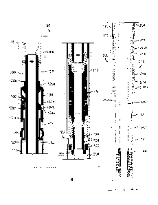
[0025] Fig. 1A illustrates a prior art technique for setting a liner top
packer using a
hydraulic setting tool.
[0026] Fig. 1B illustrates another prior art technique for setting a liner
top packer using
separate liner hanger and setting tool.
[0027] Fig. 2A illustrates an assembly according to the present disclosure
having a liner
top packer and a setting tool during run in.
[0028] Figs. 2B-2E illustrate the disclosed assembly during stages of
setting the packer.
[0029] Fig. 2F-2J illustrate the disclosed assembly during stages of
removing the setting
tool from the set packer.
[0030] Figs. 3A-3B illustrate details of a first rotatable connection for
the setting tool.
[0031] Fig. 3C illustrates details of another first rotatable connection
for the setting tool.
[0032] Fig. 4 illustrates a detail of a second rotatable connection for the
setting tool.
[0033] Fig. 5 illustrates another assembly according to the present
disclosure having a
liner top packer and a setting tool during run in.
DETAILED DESCRIPTION OF THE DISCLOSURE
[0034] FIGS. 2A through 2] show cross-sectional views of an assembly SO
according to the
present disclosure having a packer 200 and a setting tool 100. The assembly 50
is shown
in a number of positions, such as running the assembly 50 in hole (Fig. 2A) to
pulling the
setting tool 100 out of hole (Fig. 21). The packer 200 as disclosed herein can
be a liner top
packer run as a part of a liner hanger assembly. Additionally, the disclosed
packer 200 can
6
CA 2979893 2017-09-22
also be used as a tieback packer by allowing the liner to be extended to the
surface or
farther uphole in a tieback arrangement.
[0035] Looking first at Fig. 2A, the liner top packer 200 and the setting
tool 100 are
shown during run-in. The liner top packer 200 includes a housing 202. An
uphole end of
the housing 202 has an upper latch sub 204, and a downhole end is coupled to
liner tubing
14 by a coupling 12.
[0036] The packer's housing 202 has a packing assembly 210 with opposing slips
212a-b
that can ride up cones 214 on both sides of a packing element 216, such as a
compressible
elastomeric sleeve. In particular, the packing element 216 is compressible
from an
unpacked state to a packed state in the casing 10. When set, the hanging slips
212a set
toward the downhole end of the packing element 216 to keep the housing 202
from moving
downhole. Meanwhile, the hold-down slips 212b set toward the uphole end of the
packing
element 216 to keep the housing 202 from moving back uphole due to pressure
from
below.
[0037] Hydraulic setting mechanisms are not present on the setting tool 100
because the
liner top packer 200 is set with tension, as will be described below. The
setting tool 100
has an inner mandrel 102 with an upper coupling or sub 103a for attaching to a
running
string (not shown). The setting tool 100 also has an outer mandrel 101
including a cage
104 and a sleeve 110 disposed along the inner mandrel 102. A distal end of the
inner
mandrel 102 couples to a swivel 130, which is connected to a bushing assembly
120. Some
components of the setting tool 100 can extend from the bushing assembly 120
and through
the packer housing 202. As depicted in Fig. 2A, for example, an optional pup
or pipe section
140 extends from the bushing assembly 120 through the packer 200 and connects
by a
coupling 142 to a removable wiper 144.
[0038] The cage 104 includes setting slips 106 and cones 105a-b. The cage
104 also
includes drag blocks 108 that run inside the casing 10. For example, springs
(not shown)
between the drag blocks 108 and the outer mandrel 101 may force the drag
blocks 108
outwards in windows (not labeled), which drives the drag blocks 108 against
the casing 10.
This provides friction to allow for rotation of the inner mandrel 102 relative
to the cage
7
CA 2979893 2017-09-22
104. The setting slips 106 are initially held against the tool's inner mandrel
102 so as not
to engage the surrounding casing 10 during run in. The cones 105a-b are
initially held
apart so as to not push the setting slips 106 outward from the cage 104. In
particular, an
upper shearable connection 107a holds the upper cone 105a to the inner mandrel
102, and
a lower shearable connection 107b holds the lower cone 105b to the sleeve 110
of the
tool's outer mandrel 101. When released, however, the lower cone 105b can only
move
between limits relative to the cage 104 by one or more pins 104b movable in a
window
104a of the cage 104. The lower cone 105b has a slot 105d for eventual passage
of the
bayonet profile, or pins, as described later.
[0039] The outer sleeve 110 extends from the cage 104 of the setting tool
100 over the
packer's latch sub 204. A distal end 111 of the sleeve 110 on the setting tool
100 engages a
push ring 211 uphole of the packing assembly 210.
[0040] A first rotatable connection 150 exists between the outer mandrel
101 and the
inner mandrel 102 for temporarily holding them together so that the setting
slips 106
remain retracted. Briefly, the connection 150 includes mating bayonets engaged
between
the inner mandrel 102 and the outer mandrel 101 (i.e., cage 104 and/or sleeve
110).
During run in, the engaged bayonets of the connection 150 hold the mandrels
101, 102 in
place, but a partial turn (i.e., 1/6 of a turn) in one direction will release
the outer mandrel
101 from the inner mandrel 102 so the setting slips 106 can be set. Further
details are
discussed below. As an alternative to bayonets, however, the connection 150
may instead
use course threads or J-slot mechanism.
[0041] The swivel 130 transfers rotation/torque of the mandrel 102 turned
in one
direction (i.e., to the right) to the bushing assembly 120. However, the
swivel 130 clutches
when the mandrel 102 is turned in an opposite direction (i.e., to the left) so
that
rotation/torque is not transferred to the bushing assembly 120, which acts as
a second
rotatable connection. The swivel 130 can transfer torsion in axial
compression, tension, or
no load between the mandrel 102 and the bushing assembly 120. Although the
swivel 130
can operate in any of compression, tension or neutral, the disclosed assembly
50 can still
operate if the swivel 130 were only configured to transfer torque in one or
more of those
8
CA 2979893 2017-09-22
axial conditions; that condition would just have to be obtained during
operations. For
example, the swivel 130 that only transfers torque in compression would
require the string
to be in compression to transfer torque. Lastly, although preferred, use of a
swivel 130 as
disclosed is optional because the assembly 50 can operate without a swivel.
[0042] The bushing assembly 120 extending from the swivel 130 couples to the
packer
200. In particular, the bushing assembly 120 has a nut or bushing 122 disposed
on a
splined shaft 124. The splined shaft 124 couples at an uphole end to the
tool's inner
mandrel 102. It may also couple at its downhole end to the pipe section 140 if
desired.
Rotation of the tool's mandrel 102 transferred through the swivel 130 thereby
rotates the
splined shaft 124 and the pipe section 140 if present. Rotation of the splined
shaft 124
rotates the nut 122 thereon relative to internal thread 205 in the latch sub
204. Bearings
126 disengage the rotation so that rotating the running tool 100 to turn the
nut 122 in the
internal threads 205 of the latch sub 204 does not rotate the packer 200.
[0043] With an understanding of the components of the assembly 50, discussion
now
turns to its operation. Briefly, the setting tool 100 once run in hole is
operated to release
the outer mandrel 101 at the first rotatable connection 150 with rotation of
the inner
mandrel 102 and to set the setting slips 106 on the outer mandrel 101 against
the casing 10
(Figs. 2A-2C). Cementing can be performed if desired. Then, the packer 200 is
set by
pulling up against the fixed setting sleeve 110 to set the packer's element
210 (Figs. 2D-2E).
After setting the packer 200, the setting tool 100 is then released from the
packer 200 at
the second rotatable connection 120 with opposite rotation to that used to
release the first
connection 150 (Fig. 2F). The setting tool 100 is then retrieved in tension
(Figs. 2G-2j)
from the set packer 200.
[0044] Overall,
the setting procedures do not require hydraulics for actuation, and there
is no requirement for a separate liner hanger. The retrievable setting sleeve
110 and
setting tool 100 allow the packer 200 to be the set with tension, which is
advantageous in
setting a liner and the like in casing 10, for example, in shallow or deviated
wells or if rig
capacity in compression is limited.
9
CA 2979893 2017-09-22
[0045] Looking at the setting procedures in more detail, Fig. 2A shows the
assembly 50
during run-in. The setting slips 106 are held retracted from the casing 10
using spring
rings (not shown) or the like, and the packing assembly 210 (e.g., 212a-b,
214, 216) on the
packer 200 is uncompressed away from the casing 10 in which the packer 200 is
run. The
bushing assembly 120 on the setting tool 100 engages the latch sub 204 of the
housing 202
so that the setting tool 100 can run the packer 200 through the casing 10.
Meanwhile, as
depicted in Fig. 2A, the setting tool's optional pipe section 140 extends
inside the packer
200. (For simplicity, the optional pipe section 140 and some other components
depicted in
Fig. 2A are not shown in Figs. 2B-2J.)
[0046] Once the setting tool 100 runs the packer 200 to the desired depth
in the casing
10, setting procedures begin. As first shown in Fig. 2B, the inner mandrel 102
is rotated
with a first rotation, which can be to the left a partial turn (e.g., 1/6 of a
turn), to release the
first rotatable connection 150 between the inner mandrel 102 and the outer
mandrel 101.
As noted above, this release involves the first rotatable connection 150
having mating
bayonets.
[0047] As shown in Fig. 3A, for example, a portion of the inner mandrel 102 is
shown in
an isolated, perspective view and includes external bayonets 152 and a drive
face 154.
Meanwhile in Fig. 3B, a portion of the outer mandrel 101 (i.e., cage 104
and/or sleeve 110)
is shown in isolated, cross-section and includes internal bayonets 156 for
mating with the
external bayonets 152. In an initial position, the female and male components
101 and 102
mate together with the external and internal bayonets 152, 156 engaging one
another. This
allows for pushing or pulling both components 101 and 102 together as one
during run in.
With right hand rotation of the inner mandrel 102, the drive face 154 pushes
on the edges
of the internal bayonets 156 so the components 101 and 102 rotate together. By
contrast,
with left hand rotation of the inner mandrel 102, the drive face 154 separates
from the
internal bayonets 156. Once separated, the female and male components 101 and
102 are
no longer supported and pushing or pulling the male component (i.e., inner
mandrel 102)
does not move the female component (i.e., outer mandrel 101).
CA 2979893 2017-09-22
[0048] As noted above, the first rotatable connection 150 may instead use
course threads
or J-slot mechanism. For example, Fig. 3C shows a portion of the inner mandrel
102
including a course male thread 157. Female threads 159 on the outer mandrel
101 can
include one or more pins arranged about the inside of the outer mandrel 101
that can ride
in the course male thread 157 on the inner mandrel 102.
[0049] Returning to Fig. 2B, once the first rotatable connection 150 is
released,
compression applied against the inner mandrel 102 then begins to set the tool
100. The
drag blocks 108 on the cage 104 biased out to the casing 10 impede the
movement of the
cage 104, while the inner mandrel 102 can be pushed further against the cage
104.
Eventually, the inner mandrel 102 pushes the upper cone 105a toward the lower
cone
105b so that the setting slips 106 extend outward to the casing 10. As noted
above, the
upper cone 105a is secured to the mandrel 102 by the shearable connection
107a, and the
lower cone 105b is secured to the outer mandrel of cage 104 and sleeve 110 by
the other
shearable connection 107b.
[0050] As shown in Fig. 2C, the setting slips 106 set against the casing
10. More
compression on the setting tool 100 eventually shears out the upper cone 105a
from the
mandrel 102 by breaking the upper shearable connection 107a. The top sub 103a
can then
tag on the slip cage 104.
[0051] At this point, cementing operations can be performed using
techniques know to
those skilled in the art. In one method of this cementing operation, for
example, the cement
(not shown) precedes a cementing plug (not shown) and can pass down through
the
running string (not shown) and setting tool's pipe section (140: Fig. 2A). The
cementing
plug (not shown) engages the wiper (144: Fig. 2A), pushing it off the end of
the pipe section
(140: Fig. 2A), as the cement ahead of it continues down and out the liner
tubing (14) into
and up the annulus between said liner tubing and the casing 10.
[0052] When cementing is completed, operators begin setting the liner top
packer 200.
As shown in Fig. 2D, pulling up on the setting tool 100 begins to set the
packer 200. The
inner mandrel 102 can be pulled up while the cage 104 and sleeve 110 are held
in the
casing 10 by the set slips 106. The distal end 111 of the sleeve 110 contacts
a push ring
11
CA 2979893 2017-09-22
211 for the packing element 210 on the packer 200 as the setting tool 100
lifts the packer
200 uphole.
[0053] As shown in Fig. 2E, further pulling up then completes the setting
of the packer
200. In particular, further pulling uphole of the setting tool 100 moves the
inner mandrel
102, the bushing 120, the latch sub 204, and the packer 200 with it, while the
setting sleeve
110 remains fixed in the casing 10. The cones 214 wedge against the packing
slips 212a-b.
The pulling force further engages the slips 212a-b against the casing 10, and
the cones 214
move along the packer housing 202 and force against the slips 212a-b and
packing element
216 of the packer 200. To prevent reverse movement of the upper cone 214, a
body lock
ring and/or other comparable components can be used.
[0054] Eventually, the packing element 216 is compressed outward toward the
casing 10,
and the packing slips 212a-b are expanded outward against the cones 214 to
bite inside the
casing 10. The required tensile load can be applied and held for a suitable
period of time to
allow proper elastomer setting of the packer element 216.
[0055] With the packer 200 set, retrieval of the setting tool 100 then
follows. As shown in
Fig. 2F, second rotation, such as right hand rotation, of the inner mandrel
102 releases the
second rotatable connection (i.e., the bushing assembly 120). In particular,
this second
rotation of the inner mandrel 102 is transferred to the bushing assembly 120
via the swivel
130 and unthreads the running nut 122 from the internal thread 205 of the
housing's latch
sub 204. This second rotation is typically in compression to make use of the
bearing balls
126. Any suitable number of turns (e.g., approximately 11 turns) can be
required. The nut
122 has a left-hand thread and is splined to the shaft 124 of the running tool
100 so the
right hand rotation unthreads it from the latch sub 204. As noted, this second
rotation can
be opposite to the first rotation. Although less desirable, it is possible to
have the first and
second rotations be made in the same direction. In this case, a first number
of turns for the
first rotation to release can be less than the second number of turns for the
second rotation.
[0056] Once the nut 122 is unthreaded from the latch sub 204, the running
string (not
shown) and the mandrel 102 are now moved uphole. With the uphole travel, the
cage 104
and the setting sleeve 110 remain set. The uppermost male bayonet 152 on the
inner
12
CA 2979893 2017-09-22
mandrel 102, as shown in Fig. 2G, passes through the female bayonets and lower
cone slot
105d, and eventually engages the upper setting cone 105a so that upward
shifting of the
inner mandrel 102 moves the upper cone 105a from supporting the setting slips
106. With
the release of upper cone 105a, the bottom sub 103b tags against the drag cage
104, as
shown in Fig. 2H. The lower cone 105b then shears out of the drag cage 104, as
shown in
Fig. 21, by breaking the shear connection 107b. Finally, as shown in Fig. 21,
the inner
mandrel 102 is stroked until the upper cone 105a picks up on the back of the
drag cage
104. At this point, upward movement of the mandrel 102 then moves the cage 104
and
disengages the slips 106.
[0057] The cage 104 ultimately shoulders out on the sleeve 110, and the
setting tool 100
can be pulled out of hole. Although not depicted, the distal end 111 of the
sleeve 110 can
simply separate from the push ring 211 as the sleeve 110 is pulled further
upward with the
setting tool 100. Once the setting tool 100 has been removed, further
operations can then
be performed by running tubing to the upper sub 204 of the packer 200 to tie
back the liner
farther uphole or to the surface in a tieback arrangement.
[0058] In the previous arrangement, the disclosed assembly 50 sets the
anchor slips 106
with an initial movement in a downhole direction with resistance provided by
the drag
blocks 108 against the casing. As an alternative, another assembly 50
according to the
present disclosure is illustrated in Fig. 5 having a liner top packer 200 and
a setting tool
100 during run in. Components of this assembly 50 are similar to those
disclosed
previously so that like reference numerals are used for comparable components.
Moreover, as will be appreciated, such comparable components may operate in
the same
way, which may not be specifically readdressed with reference to Fig. 5.
[0059] In this assembly 50, the drag cage 104 and drag blocks 108 are
disposed uphole
from the slip cage 110, anchoring slips 106, and cones 105a-b. In this way,
the disclosed
assembly SO sets the anchor slips 106 with an initial movement in an uphole
direction with
the resistance provided by the drag blocks 108 against the casing 10.
[0060] In particular, the drag cage 104 holds the drag blocks 108, which
are biased
outward to the casing 10 by springs (not shown). The drag cage 104 is
connected to the
13
CA 2979893 2017-09-22
inner mandrel 102 by the first rotatable connection 150, which can include
bayonets,
course thread, or J-slot mechanism as noted herein. The drag cage 104
temporarily couples
with shear screws 107a or the like to the upper cone 105a disposed in the
space between
the inner mandrel 102 and the slip cage 110 of the outer mandrel 101. The
anchoring slips
106 are disposed in windows 116 of the slip cage 110 and are held against the
inner
mandrel 102 with slip springs (not shown).
[0061] At the opposing end of the slips 106, the slip cage 110 engages with
a shoulder 113
against the lower cone 105b, which temporarily couples with shear screws 107b
or the like
to the inner mandrel 102. The lower cone 105b is spaced from a pin 109 on the
inner
mandrel 102, and the lower cone 105b includes a slot 105d for eventual passage
of the pin
109, as described later.
[0062] Finally, the slip cage 110 includes a setting sleeve 112 that
extends along the
outside of the swivel 130, second rotatable connection 120, and tie back sub
204 toward
the packer 200. During run-in as shown, the distal end of the setting sleeve
112 is
distanced from an engagement ring/push ring 201 on the packer 200.
[0063] When the assembly 50 is run to the desired position in the casing
10, the inner
mandrel 102 is turned (and optionally also pulled up) to release the first
rotatable
connection 150 of the bayonets, course thread, J-slot or the like. This
releases the inner
mandrel 102 from the drag cage 104 and slip cage 110. Pulling up on the inner
mandrel
102 then sets the anchor slips 106 as the lower cone 105b connected to the
inner mandrel
102 wedges against the slips 106 and the upper cone 105a is held by the drag
blocks 108
encountering friction against the casing 10.
[0064] Additional tension on the inner mandrel 102 then shears the inner
mandrel 102
from the lower cone 105b when the shear screws 107b shear. Lifting of the
inner mandrel
102 then moves the packer 200 up to the setting sleeve 112. Additional tension
on the
inner mandrel 102 then shears and sets the packer 200. Once the packer 200 is
set, the
inner mandrel 102 is rotated to release the second rotatable connection 120,
which can
include the bushing nut, spline, and the like. Of course, other rotatable
connections can be
used.
14
CA 2979893 2017-09-22
[0065] Pulling up of the inner mandrel 102 then guides the pin 109 on the
mandrel 102
past the lower cone 105b (i.e., under the slot 105d) so that the pin 109 tags
against the
upper cone 105a. Further pulling up causes the pin 109 to shear the upper cone
105a free
of the drag cage 104, and the slot pins 105c on the upper cone 105a engage in
the window
115 of the slip cage 110. Continued pulling up on the inner mandrel 102 causes
the slip
cage 110 to engage the drag cage 104 at shoulders 117. Then, the slip cage's
shoulder 113
eventually re-contacts the lower cone 105b so that the setting tool 100 of the
assembly 50
can be pulled out of hole while the packer 200 remains set in the casing 10.
[0066] The foregoing description of preferred and other embodiments is not
intended to
limit or restrict the scope or applicability of the inventive concepts
conceived of by the
Applicants. It will be appreciated with the benefit of the present disclosure
that features
described above in accordance with any embodiment or aspect of the disclosed
subject
matter can be utilized, either alone or in combination, with any other
described feature, in
any other embodiment or aspect of the disclosed subject matter.
[0067] It is understood that any reference to right-hand rotation above may
be replaced
with left-hand rotation. However, right-hand rotation is generally preferred
as this
prevents unthreading of the conventional right-hand threaded tubulars. It is
also
understood that any mention of direction (e.g, uphole, downhole, up, down,
etc.) is merely
relative to facilitate explanation. In this regard, although the disclosed
packer 200 and
setting tool 100 have been disclosed with various components toward uphole and
downhole ends and with operations in uphole and downhole directions, it will
be
appreciated that these orientations and directions can be reversed in a
desired
implementation.
[0068] In exchange for disclosing the inventive concepts contained herein,
the Applicants
desire all patent rights afforded by the appended claims. Therefore, it is
intended that the
appended claims include all modifications and alterations to the full extent
that they come
within the scope of the following claims or the equivalents thereof.
CA 2979893 2017-09-22