Note: Descriptions are shown in the official language in which they were submitted.
CA 02979959 2017-09-15
1
DEVICE FOR CLEANING AND PROCESSING THE RECTUM AND PELVIS OF
SLAUGHTERED PIGS AND THE OPERATING METHOD FOR THE DEVICE
Object of the invention
More specifically, the invention relates to a device for cleaning and
processing the
rectum and pelvis of slaughtered pigs and the operating method of the device
the arrangement
of which is mainly mechanical in nature, which allows it, in a period of about
2 to 3 seconds, to
enter the animal's rectum, cut it out, create an incision in the animal's
pelvis and, simultaneously
clean and sterilise itself, as the device incorporates a semi-enclosed chamber
in which this
process can take place.
State of the Art
Devices for the cleaning and processing of the rectum of slaughtered pigs are
available
on the market and they can, therefore, be considered as the state of the art,
this cleaning
usually takes place on the continuous chains commonly found in all industrial
slaughterhouses,
for example, that described and claimed in European Patent No. 1,115,292.
Said patent consists of an apparatus with a means of suction for a
disinfectant substance,
supplied to a cavity occupied by a cylindrical blade, separated from the means
in order to
establish the negative pressure to empty a part of the rectum and comprising
an arrangement
for establishing an additional negative pressure in said cavity.
Another of the references contained in the state of the art is European Patent
No.
457,409 which describes and claims a device for separating the pubis from the
body of a
slaughtered animal, specifically that of a pig comprising a positioning
element, a rotating
cylindrical cutter and a blade-like cutting disc that are combined in a
functional unit that can be
moved in its entirety from the carcass.
Another of the references found is European Patent No. 258,939, the object of
which is a
piece of equipment for cutting and opening the body of a dead animal, mainly
the pubis of the
carcass of the dead animal, an element for positioning the slaughtered animal
is claimed, an
initial cutting element and a second cutting element, together with a sensor
coupled to the
second cutting element for locating the pubis, all combined in a functional
unit.
In all the embodiments of these references the cleaning of the parts that make
up the
devices can clearly be improved, since in most cases this is carried out
automatically by
submerging the cutting head in a tank containing water and disinfectant,
which, although it
cleans automatically, does not ensure the cleaning.
CA 02979959 2017-09-15
2
Purpose of the Invention
To improve the cutting of the rectum and sectioning of the pelvis and the
subsequent
cleaning of the means used for this purpose, all without delaying the movement
of the
continuous chains that industrial slaughterhouses are equipped with.
Description of the Invention
The present invention is defined in the attached claims.
Health in the field of human food products requires solutions to be found that
improve
the state of the art and, more specifically in our case, requires the creation
of means to ensure
the perfect handling of animals, preferably but not exclusively pigs, to
prevent these solutions
from contaminating the entire process of cutting up the animal, as well as
certain shortcomings
that force the withdrawal of some units, where a bad cut to the pig can mean
that some parts
must be discarded, with the consequent economic losses.
Within the cutting process, and in one of the initial stages, the rectum of a
slaughtered
pig must be removed, first by cutting it and then by removing it, evacuating
the deposits it
contains, without this resulting in a loss of hygiene or the contamination of
the other parts of the
animal and, simultaneously, or subsequently, an incision has to be made in the
pelvis that
allows the separation of the hind quarters.
The present invention consists of, that in an orderly manner after cutting and
removing
the rectum and evacuating the deposits it contains, the means used in such
operations are
cleaned effectively, including the blade and the mandrel introduced in a
programmed way within
the animal's rectum.
The cleaning of the device is possible as the design allows for these means,
comprising
a mandrel and some cutting knives, to remain for a period of some 2 to 3
seconds inside a
cavity formed by the closing together of two articulated valves, so that the
cavity is formed when
one valve drops onto the other, pressurised water or disinfectant or a
combination of them is
introduced into the interior through an input conduit so as to clean
everything that is inside the
cavity mainly the mandrel and the cutting blades, the fluids are then
evacuated along with
particles of dirt collected by the cleaning through an output provided in the
lower valve.
These valves, in addition to being designed so that their edges are facing
each other
when the upper valve drops over the lower one forming a semi-enclosed chamber,
also have
means that allow them to move from a position on the far left of the device,
where they are
completely separate, to the extreme right where they together, one over the
other.
These means comprise a set of levers that, at one end, are attached to the
body of the
valves, while at the opposite end they are attached to supports or slides that
push the
CA 02979959 2017-09-15
3
articulated levers by means of connecting rods, one end of which is joined to
the levers, while at
the other end these rods are attached to the head of a stem that moves from
right to left and
vice versa, through the action of a pneumatic or hydraulic cylinder on the
stem.
The action of opening and closing the cavity, which involves the separation of
the valves
and their coming together respectively, takes place in combination with the
action of a mandrel
that slides to the right and left and vice versa, as well as the extension of
the mandrel in
conjunction with it, along with a knife that also describes the same movement
and which
produces an incision to the animal's hind quarters breaking the pelvis,
without cutting the thighs
or hams which are handled separately once the pig has been cut apart, if these
parts were cut
they could not then be used with the consequent economic loss.
Other details and characteristics will become apparent in the description
provided below,
in which reference is made to the figures in which a practical embodiment of
the invention is
shown by way of illustration that is not limiting, it can be carried out with
all kinds of materials
where they are appropriate.
Description of the figures
The following is a list of the different parts of the invention, which are
located in the
following figures using the numbers listed below: 10 arrangement, 11 upper
valve, 12 lower
valve, 13 fluid output, 14 lower base, 15 set of levers, 16,17 levers, 18
blade, 19 blade holder,
20 mandrel, 20b lateral surface of the mandrel, 21 extension, 22 pneumatic
and/or hydraulic
cylinder, 23 support rod, 24 stem, 25 head, 26 joints, 27 connecting rods, 28
semi-enclosed
cavity, 29 joints, 30 screws, 31 knife support, 32 slide, 33 bench, 34
mounting plate support, 35
robot, 36 tubular element, 37 arm, 38 appendages, 39 guide rail, 40 plates, 41
water input
conduit, 42 circular blade.
Figure No. 1 is a side elevation view of the device 10, in which it is
possible to see the
upper and lower valves 11,12 articulated by the levers 16,17.
Figure No. 2 is a side elevation view of the device 10, showing the valves
11,12,
displaced to the right by the movement of the levers 16,17 due to the action
of the pneumatic
cylinder 22 on the connecting rods 27 and on these levers 16,17, covering the
mandrel 20 and
the extension 21 with the valves 11,12 forming the semi-enclosed cavity 28.
Figure No. 3 is a partial side elevation view of the device 10 with the parts
that allow the
movement of the valves 11,12, this occurs as they are arranged at one end of
the levers 16,17,
their rotation with respect to the support plates 23 with the aid of the
joints 26 and 29 connected
to the connecting rods 27 and these rods connection to the head 25 of the stem
24 of the
pneumatic cylinder 22.
CA 02979959 2017-09-15
4
Figure No. 4 is a similar view to Figure No. 3 in which the valves 11,12 are
withdrawn to
the left of the device 10.
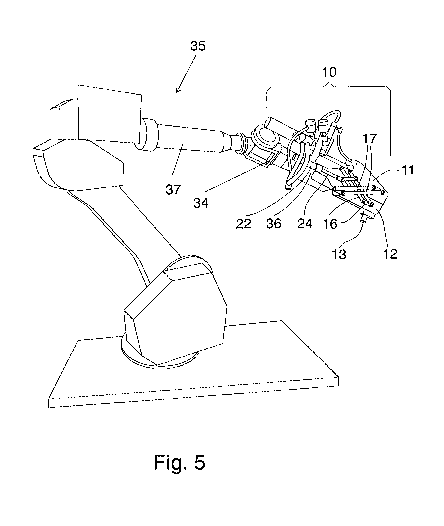
Figure No. 5 is a perspective view of the device 10 mounted on a bench 33 and
the latter
to a plate support 34 mounted on an arm 37, which attaches to a robot 35 not
detailed in this
figure.
Preferred embodiment of the invention
In one of the preferred embodiments of the invention and as can be seen in
Figure No. 5
the recommended device 10 is available on a conventional robot 35 and, by
means of a support
plate 34, mounted on an arm 37 of the robot 35, for which it is attached to a
tubular element 36
perpendicular to said support plate 34, which incorporates the pneumatic or
hydraulic cylinder
22 that operates the levers 16,17, attaching the levers 16,17 to the support
plates 23 that are
moved to either side of the tubular element 36 with the aid of the appendages
38 that form a
single piece with the support plates 23 as described below.
The core of the invention is the device 10, although to facilitate the
understanding of the
invention from the perspective of Figure No. 5 only part of it has been
reproduced, based on a
robot 35 and a robot arm 37, the robot 35 is completely conventional and, as
indicated
previously the device 10 is mounted on the robot 35.
As the device 10 is asymmetrical it is reproduced in Figures No. 1 - 4, for
greater
precision in the description, such that in Figure No. 1 the two valves 11,12
appear in the
extreme left position, exposing the mandrel 20 which emerges from the end of
the tubular
element 36.
These valves 11,12 move from the position indicated in Figure No. 1, to a
position to the
extreme right represented in Figure No. 3, it being possible for these valves
11,12 to make this
movement from left to right and vice versa by the combined action of a set of
levers 15.
The aforementioned set of levers 15 as can be seen in Figure No. 2 includes
the levers 16,17
themselves, whose ends are attached at one end to the valves 11,12,
reinforcing the valves
11,12 with plates 40 and the opposite ends are attached to support plates 23
and connecting
rods 27, which at one end join the levers 16,17 and at the other join the head
25 of a shaft 24 of
a pneumatic or hydraulic cylinder 22, where the action of pushing the stem 24
forces the
connecting rods 27 to push or pull the levers 16,17, with the aid of the
corresponding joints 26.
The extension 21 extends out of one end of the mandrel 20 allowing the passage
of air
and water within it to place the mandrel 20 and the extension 21 into the
working position inside
the animal's rectum, which surrounds the lateral surface 20b of the mandrel 20
so that it is
possible to cut it out due to the action of a blade 18 mounted on the blade
holder 19 and this
CA 02979959 2017-09-15
blade holder 19 is attached to the knife support 31, which moves left and
right along the guide
rail 39 as can be seen in Figures No. 1 and 2.
As a characteristic of the invention, the function of the valves 11,12 when
folded one
over the other, see Figures No. 3 and 5, is to create a semi-enclosed cavity
into which water
5 and air is injected by the input conduit 41 in the upper valve 11 for
cleaning both the blades 18
and 42 as well as the mandrel 20 and its extension 21 when they have finished
their work and
are in the interior of this semi-enclosed cavity, which takes advantage of the
time that passes
between the cutting of one animal and the next on the continuous chain, as
part of this cleaning
the dirty water discharges through the fluid output 13 at the bottom of the
bottom valve 12, as a
result the mandrel 20, the extension 21 and the blades 18 and 42 do not come
into contact with
dirty water and they will, therefore, not contaminate the next animal.
The operating cycle of the device 10 begins when the already slaughtered
animal, which
is hanging by its hind quarters from the continuous chain, is placed by
appropriate means in
front of the device 10 and remains still for around 2 to 3 seconds, when the
following
movements take place.
The extension 21 and mandrel 20 are introduced through the animal's rectum to
a
predetermined depth, leaving the blade 18 facing the animal's hind quarters.
- The mandrel 20 extends from the left to the right inside the rectum and
removes it with
the help of a circular blade 42, located at the right end of the mandrel 20
sucking the pieces of
the rectum and the faeces contained therein through the duct provided in the
extension 21.
- The blade 18 moves from left to right due to the action of the knife
support 31, which
moves along the guide rail 39 and produces an incision in the central part of
the pelvis.
The blade 18 moves back from right to left due to the action of the knife
support 31
guided by the guide rail 39, along with the mandrel 20 and the extension 21,
the valves 11,12
are closed forming a semi-enclosed cavity 28 and simultaneously water and air
enter through
the input conduit 41, when inside the semi-enclosed cavity 28 this water
cleans the blades 18
and 42 the mandrel 20 and the extension 21, the water and dirt leave by the
output 13.
The present invention is sufficiently described in correlation with the
attached figures, it
is easy to understand that any detailed modifications could be made to it that
may be deemed
suitable, provided that the invention is not disturbed, which is summarised in
the following
claims.