Note: Descriptions are shown in the official language in which they were submitted.
CA 02980119 2017-09-18
WO 2016/171702 PCT/US2015/027342
STABILIZER DEVICES FOR DRILLING TOOL HOUSING
Technical Field
[0001] The
present disclosure relates generally to an assembly for a motor
shaft transmission and, more particularly (although not necessarily
exclusively), to
assemblies and methods for mounting a stabilizer device on a mud motor
housing.
Background
[0002]
Stabilizers of varying gauges may be mounted to the outer housing of a
mud motor. A threaded connection may be used to mount a stabilizer device to a
mud motor housing. The threaded connection may be oriented such that the
stabilizer device may pass over the lower connection of the motor, the
driveshaft
shoulder, and the lower section of the outer motor housing with room to tong
on the
body of the stabilizer device to torque the threaded connection according to a
desired specification. The threaded connection may serve to locate the
stabilizer
device axially on the housing and, resist drag forces moving axially uphole or
downhole. The threaded connection may also serve to carry torque loads from
the
friction drag interaction between the stabilizer and the wellbore wall when
the motor
is turned from the surface of the wellbore.
[0003] But,
threads on the motor housing may have several disadvantages,
making them undesirable for mounting a stabilizer device to a motor housing.
For
example, the abundance of stress raisers (e.g., thread roots, relief geometry)
may
aggravate fatigue and promote crack initiation. Also, threads on the motor
housing
are often damaged and may require time and cost penalties to extend the
service life
of the threaded stabilizer and motor housing. In some instances, significant
thread
damage may require replacement of an expensive motor housing.
Further,
threading on the motor housing may require increased third-party inspection,
which
1
CA 02980119 2017-09-18
WO 2016/171702 PCT/US2015/027342
may result in lost time and money due to additional cleaning done prior to
inspection
and the downtime of the drilling operations during the inspections. Similarly,
threading on the motor housing may also require formal verification-of-torque
processes and inspection as part of quality management procedures.
Brief Description of the Drawings
[0004] FIG. I is a cross-sectional schematic diagram depicting a drilling
system that includes a motor shaft transmission assembly with an interference
apparatus in a lower end of a downhole motor assembly according to one aspect
of
the present disclosure.
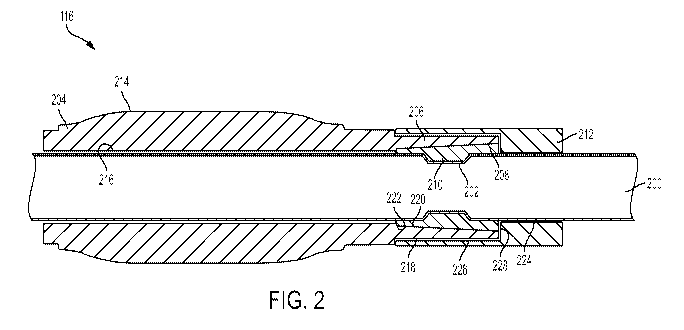
[0005] FIG. 2 is a cross-sectional view of a mud motor drilling assembly
with a
stabilizer device according to one aspect of the present disclosure.
[0006] FIG. 3 is a perspective view of a disassembled stabilizer device of
the
mud motor drilling assembly of FIG. 2 according to one aspect of the present
disclosure.
[0007] FIG. 4 is a cross-sectional view of a mud motor drilling assembly
with
stabilizer device according to another aspect of the present disclosure.
[0008] FIG. 5 is a perspective view of the stabilizer device of the mud
motor
drilling assembly of FIG. 4 according to one aspect of the present disclosure.
Detailed Description
[0009] Certain aspects and examples of the present disclosure relate to an
assembly for mounting a stabilizer device on a motor housing of a mud motor
drilling
assembly without the use of threads on the motor housing to locate the
stabilizer.
For example, a clamp may be used to couple the stabilizer device to the motor
housing. In some aspects, an internal ridge on one or more split-ring shells
may be
inserted into a groove on the motor housing. In an alternative aspect, the
split-ring
2
CA 02980119 2017-09-18
WO 2016/171702 PCT/US2015/027342
shells may include an internal groove to receive a ridge on the motor housing.
The
stabilizer device may be placed on the motor housing near the groove or ridge
to
allow a threaded portion of the stabilizer device to rest on the one or more
split-ring
shells. The clamp may have threads corresponding to threads on the threaded
portion of the stabilizer device to couple the stabilizer device to the motor
housing.
In other aspects, the stabilizer device may be placed on the motor housing
near a
groove on the motor housing to allow the threaded portion to be received in a
groove. The clamp may be threadably coupled to the threaded portion to couple
the
stabilizer device to the motor housing.
[0010] Stabilizer devices are considered consumable components of the
drilling system due to the interference of stabilizer device with the walls of
a wellbore
during operation. This interference makes the stabilizer device subject to
wear and
fatigue. The reduced fatigue life due to the presence of the threads on the
stabilizer
device may be tolerable, provided the minimum life criteria ensures at least
one run
cycle. Particularly, the assembly of the stabilizer device allows the
stabilizer device
to be easily demounted or uninstalled from the motor housing for replacement
or
repair. Threaded connections on the stabilizer device and not the housing, in
addition to the ease of assembly and disassembly may save time and costs in
repair,
inspection, and replacement costs to the motor housing in exchange for less
expensive replacement and repair of the stabilizer device.
[0011] A mud motor drilling assembly may include a motor housing and a
stabilizer device. The motor housing may include one or more grooves on or one
or
more ridges in an external surface for mounting the stabilizer device to the
motor
housing. The stabilizer device may include a threaded portion that has an
external
surface with threads. The threads may correspond to threads on an internal
surface
3
CA 02980119 2017-09-18
WO 2016/171702 PCT/1JS2015/027342
of a clamp. The threads on the threaded portion may be mated with the threads
on
the clamp. The threaded portion may be positioned between the one or more
grooves or ridges and the clamp. The threaded coupling of the clamp to the
stabilizer device may couple the stabilizer device to the motor housing at the
one or
more grooves. In some aspects, the threaded portion may be positioned between
split-ring shells mounted in a groove or ridge on the motor housing and the
clamp. In
other aspects, the threaded portion may be positioned in a groove on the motor
housing.
[0012] The terms "inner," "outer," "internal," "external," and "between,"
as used
in the present disclosure may refer to a radial orientation toward or away
from the
center of the mud motor drilling assembly. The terms "uphole" and "downhole,"
as
used in the present disclosure may refer to an axial orientation toward or
away from
the surface.
[0013] Various aspects of the present disclosure may be implemented in
various drilling systems. FIG. 1 illustrates an example of such a drilling
system 100
that includes a drill string 102. The drill string 102 of a drilling rig (not
shown) may
include segmented pipes that may extend below the surface 104 in a borehole,
such
as a wellbore 106. The drill string 102 may transmit drilling fluid (or mud)
and the
torque necessary to operate a drill bit 108. Also, the weight of the drill
string 102
may provide an axial force on the drill bit 108.
[0014] The drill string 102 may include a drill pipe 110 and a bottom hole
assembly 112. The bottom hole assembly 112 may be include various components,
such as a downhole motor assembly 114 and the drill bit 108.
[0015] Though placement of the assemblies disclosed herein may vary
without departing from the scope of the present subject matter, the assemblies
of the
4
CA 02980119 2017-09-18
WO 2016/171702 PCT/US2015/027342
present disclosure may be included in the lower end of the downhole motor
assembly 114 and near the drill bit 108. For example, the mud motor drilling
assembly 116 of FIG. 1 represents a placement according to one example.
Placement of the assemblies as close to the drill bit 108 as possible may
enhance
the mechanical stability of the drilling system 100. For example, the
assemblies of
the present disclosure may prevent unintentional sidetracking of the drill bit
108 and
vibrations of the drill pipe 110 and drilling components attached thereto.
[0016] FIG. 2 shows a cross-sectional view of a mud motor drilling
assembly
116 that may be positioned in the downhole motor assembly 114 of the drilling
system 100 of FIG. 1. The mud motor drilling assembly 116 may include a motor
housing 200. The motor housing 200 includes a groove 202 on its external
surface
for mounting a stabilizer device included in the mud motor drilling assembly
116.
The groove 202 may serve to locate or mount the stabilizer device on the motor
housing 200. Although one groove 202 is shown, the motor housing 200 may
include any number of grooves 202 for mounting the stabilizer device to the
motor
housing 200. The stabilizer device includes a stabilizer body 204, a threaded
portion
206, and split-ring shells 208. The split-ring shells 208 include a ridge 210
on an
internal surface corresponding to the groove 202 on the motor housing. The
stabilizer device also includes a clamp 212 for coupling the stabilizer device
to the
motor housing 200.
[0017] The stabilizer body 204 includes an outer body 214 and an inner
body
216. During operation of the drilling system 100, the outer body 214 may
interfere
with the walls of the wellbore 106 to stabilize the drilling system 100. In
some
aspects, the outer body 214 may be made of a wear-resistant material or hard-
faced
and may include blades or other protrusions. The inner body 216 is positioned
CA 02980119 2017-09-18
WO 2016/171702 PCT/US2015/027342
against the external surface of the motor housing 200. The split-ring shells
208 may
be positioned on the motor housing 200 between the groove 202 and the threaded
portion 206. The split-ring shells 208 may be located on the motor housing 200
by
positioning the ridge 210 in the groove 202 on the motor housing. Although one
ridge 210 is shown on each of the split-ring shells 208, any number of ridges
may be
included on the split-ring shells 208. For example, the groove 202 in the
motor
housing 200 may be sized to receive two or more ridges 210. In another
example,
the number of ridges 210 may correspond to the number of grooves on the motor
housing 200 and each groove 200 may be sized to receive a ridge 210. In some
alternative aspects, the split-ring shells 208 may include a groove in place
of the
ridge 210 corresponding to a ridge on the motor housing 200 in place of the
groove
202 to mount the split-ring shells 208 to the motor housing 200. The groove on
the
split-ring-shells 208 may be sized to receive the ridge on the motor housing
200.
[0018] The threaded portion 206 of the stabilizer device is integral to
the
stabilizer body 204 and is positioned between the groove 202 and the clamp
212,
external to the split-ring shells 208. The threaded portion 206 includes an
external
surface 218 and an internal surface 220. The external surface 218 of the
threaded
portion 206 may include threads for coupling the clamp 212 to the stabilizer
device.
The internal surface 220 of the threaded portion 206 is positioned against the
split-
ring shells 208. In some aspects, the internal surface 220 may include a taper
corresponding to a taper on an external edge of the split-ring shells 208. The
internal surface 220 includes an internal surface edge 222. The internal
surface
edge 222 may support the stabilizer device in the axial direction when the
stabilizer
device is mounted on the motor housing 200. For example, the internal surface
6
CA 02980119 2017-09-18
WO 2016/171702 PCT/US2015/027342
edge 222 may interfere with the split-ring shells 208 when drag forces moving
axially
uphole and downhole are placed on the stabilizer device.
[0019] The clamp 212 may couple the stabilizer device to the motor housing
200. The clamp 212 may be a cap, ring, bolt, or any component made of a
resilient
material (e.g., steel) for coupling the stabilizer device to the motor housing
200. The
clamp 212 includes an inner surface 224. The inner surface 224 may have an
inner
diameter sized to be slid onto or otherwise positioned on the motor housing
200.
The inner surface 224 has an inner channel 226 for receiving the split-ring
shells 208
and the threaded portion 206. The inner surface 224 may also include threads
in the
inner channel 226 corresponding to the threads on the external surface 218 of
the
threaded portion 206. The clamp 212 may be threadably coupled to the
stabilizer
device by mating the threads on the threaded portion 206 with the threads on
the
clamp 212. The threaded coupling of the clamp 212 to the stabilizer device
couples
the stabilizer device to the motor housing 200. The inner channel 226 of the
clamp
212 includes a channel edge 228. The channel edge 228, similar to the internal
surface edge 222 of the threaded portion 206 supports the stabilizer device in
the
axial direction by interfering with the split-ring shells 208 when drag forces
moving in
the axial direction (uphole and downhole) are placed on the stabilizer device.
[0020] The stabilizer device may be symmetrical about its axis such that
the
radial distance from the axis of the motor housing 200 to the outer diameter
of the
stabilizer body 204 is constant as shown in FIG. 2. In some aspects, the
stabilizer
device may be offset such that blades or other protrusions on the stabilizer
body 204
may include varying radii from the axis of the motor housing 200 to the outer
diameter of each blade or protrusion. For example, the blades or protrusions
on one
side of the motor housing 200 include different radii from the axis of the
motor
7
CA 02980119 2017-09-18
WO 2016/171702 PCT/US2015/027342
housing 200 to the outer diameter of the blades or protrusions than blades or
protrusions on an opposing side of the motor housing 200. In another example,
there may be a blade on only one side of the stabilizer body 204 to form an
offset
pad arrangement. The arrangement may require orientation about the axis of the
motor housing 200 in addition to an axial restraint.
[0021] FIG. 3 shows a disassembled, perspective view of the stabilizer
device.
The outer body 214 of the stabilizer device includes blades 300 for
interfering with
the walls of the wellbore 106 during operation of the drilling system 100.
Although,
the blades 300 are shown to be spiraled around the outer body 214 of the
stabilizer
device, the blades 300 or other protrusions have various shapes (e.g.,
straight)
according to the design specifications of the stabilizer device. The external
surface
218 of the threaded portion 206 of the stabilizer device includes threads 302.
The
threads 302 correspond to threads 304 in the inner channel 226 on the inner
surface
224 of the clamp 212. For example, threads 302 may be female threads and
threads
304 may be male threads. The threads 302 on the threaded portion 206 are
positioned near an end of the threaded portion 206. The threads 304 on the
clamp
212 are positioned near the clamp 212. The position of the threads 302, 304 on
the
threaded portion 206 and clamp 212, respectively, may vary according to the
design
specifications of the stabilizer device. Similarly, threads 302, 304 may
include
multiple sets of threads (e.g., threads 302 including a set of threads at one
end of the
threaded portion 206 and a set of threads at an opposite end of the threaded
portion
206). In some aspects, the placement of the threads 302, 304 may be dependent
on
the size or position of the split-ring shells 208 relative to the size of the
threaded
portion 206 or clamp 212.
8
CA 02980119 2017-09-18
WO 2016/171702 PCT/US2015/027342
[0022] The split-ring shells 208 have an inner diameter sized for mounting
to
the motor housing 200. In some aspects, diameter of the split-ring shells 208
may
allow the ends of the split-ring shells 208 to connect to form a continuous
ring when
mounted on the motor housing 200. In other aspects, the diameter of the split-
ring
shells may allow gaps between the ends of the split-ring shells 208 to form an
open
ring when mounted on the motor housing 200. Although two split-ring shells 208
are
show, the split-ring shells may be any number of shells, including one. The
shells
may be made out of any resilient material (e.g., steel, tungsten carbide,
etc.).
[0023] To install the stabilizer device onto the motor housing 200, the
split-ring
shells 208 may be mounted onto the motor housing 200. The ridge 210 on the
inside of the split-ring shells 208 may be positioned in the groove 202 on the
motor
housing 200. The stabilizer device may be positioned proximate to the groove
202
on the motor housing 200 so that the internal surface 220 of the threaded
portion
206 is positioned against the split-ring shells 208 mounted in the groove 202.
The
threads 304 on the clamp 212 may be mated with the threads 302 on the threaded
portion 206 to couple the clamp 212 and the threaded portion 306. The threads
302,
304 may be positioned for the split-ring shells 208 and the threaded portion
206 to
be received in the inner channel 226 of the clamp 212 as the clamp 212 is
threadably coupled to the threaded portion 206. The coupling of the clamp 212
to
the threaded portion 206 couples the stabilizer device to the motor housing
200. The
stabilizer device is supported in the radial direction by the clamp 212. The
stabilizer
device is supported in the axial direction by the channel edge 228 on one
axial end
of the split-ring shells 208 and the internal surface edge 222 on the opposing
axial
end of the split-ring shells 208.
9
CA 02980119 2017-09-18
WO 2016/171702 PCT/US2015/027342
[0024] FIG. 4 shows a cross-sectional view of another example of a mud
motor drilling assembly 116A that may be positioned in the downhole motor
assembly 114 of the drilling system 100 in place of mud motor drilling
assembly 116
of FIG. 1. The mud motor drilling assembly 116A may include a motor housing
400
having a groove 402. The mud motor drilling assembly 116A also includes a
stabilizer device having a stabilizer body 404, a threaded portion 406, a
flexure
portion 408, and a clamp 410. The stabilizer body 404 includes an outer body
412
and an inner body 414. During operation of the drilling system 100, the outer
body
412 may interfere with the walls of the wellbore 106 to stabilize the drilling
system
100. In some aspects, the outer body 412 may be made of a wear-resistant
material
or hard-faced and may include blades or other protrusions. The inner body 414
is
positioned against the external surface of the motor housing 400. The threaded
portion 406 of the stabilizer device may be sized to be received in the groove
402 of
the motor housing 400. The threaded portion 406, when positioned in the groove
402 may support the stabilizer device in the axial direction by interfering
with the
edges of the groove 402 when drag forces are applied to the stabilizer device
in the
axial direction. The clamp 410 may support the clamp in the radial direction.
The
clamp 410 may be torqued against a shoulder of the threaded portion 406 near
the
flexure portion 408 to ensure that the clamp 410 does not decouple from the
threaded portion 406 during operation of the drilling system 100.
[0025] FIG. 5 shows a perspective view of the stabilizer device of FIG. 4.
The
threaded portion 406 is integral to the stabilizer body 404 and the flexure
portion
408. The threaded portion 406 may include threads 500 on an external surface
of
the threaded portion 406 corresponding to threads on an inner surface of the
clamp
410 for coupling the clamp 212 to the stabilizer device and coupling the
stabilizer
CA 02980119 2017-09-18
WO 2016/171702 PCT/US2015/027342
device to the motor housing 400. The threads 500 include two sets of threads,
positioned at opposing ends of the external surface of the threaded portion
406. Any
number or set of threads 500 may be included on the threaded portion 406. The
threads 500 may also be positioned anywhere on the threaded portion 406 to
mate
with the threads on the clamp 410.
[0026] The flexure portion 408 of the stabilizer device is integral to the
stabilizer body 404 and connects the threaded portion 406 to the stabilizer
body 404.
The flexure portion 408 may have bending properties (e.g., a hinge, crease,
score,
etc.) to increase the diameter of the threaded portion 406 as the stabilizer
device is
installed on the motor housing 400. The bending properties of the flexure
portion
408 may position the threaded portion 406 in the groove 402 on the motor
housing
400 when the flexure portion 408 is proximate to the groove 402 and the
threaded
portion 406 is positioned external to the groove 402. The flexure portion 408
may
include castellations 502, or slits, that extend to the threaded portion 406.
The
castellations 502 extend partially through the flexure portion 408. The
castellations
502 extend fully through the threaded portion 406 to create latch blocks of
the
threaded portion 406 sized to be received by the groove 402. The castellations
502
may allow for the increase in diameter of the threaded portion 406 by the
flexure
portion 408. The castellations 502 may be of any length or quantity without
departing from the scope of the present disclosure.
[0027] To install the stabilizer device onto the motor housing 400, the
stabilizer device may be slid or otherwise positioned on the motor housing
400. The
positioning of stabilizer device on the motor housing 400 may force the
flexure
portion 408 to a larger diameter, the flexure portion 408 in turn forcing the
threaded
portion 406 to a larger diameter, to pass over the diameter of the motor
housing 400.
11
CA 02980119 2017-09-18
WO 2016/171702 PCMS2015/027342
The stabilizer device may be positioned proximate to the groove 402 so that
the
threaded portion 406 is positioned external to the groove 402. The bending
properties of the flexure portion 408 may allow the flexure portion 408 to
position the
threaded portion 406 in the groove 402 and return the flexure portion 408 and
threaded portion 406 to its original diameter. The clamp 410 may be threadably
coupled to the stabilizer device by mating the threads 500 on the threaded
portion
406 with corresponding threads on the clamp 410. The coupling of the clamp 410
to
the threaded portion 406 couples the stabilizer device to the motor housing
400.
[0028] In some aspects, the mud motor drilling assemblies are provided
according to one or more of the following examples:
[0029] Example #1: A mud motor drilling assembly may include a motor
housing having a groove or ridge for mounting a stabilizer device to the motor
housing. The mud motor drilling assembly may also include the stabilizer
device.
The stabilizer device may be external to the motor housing and include a
threaded
portion having external threads on an external surface of the threaded portion
corresponding to internal threads on a clamp for coupling the stabilizer
device to the
motor housing. The threaded portion may be positioned between the clamp and
the
groove or the ridge.
[0030] Example #2: The mud motor drilling assembly of Example #1 may
feature the stabilizer device further including a stabilizer body. The
stabilizer body
may have an outer body and an inner body. The outer body may have stabilizer
blades for interfering with a wellbore wall. The inner body may be positioned
against
the motor housing.
[0031] Example #3: The mud motor drilling assembly of Example #2 may
feature the threaded portion of the stabilizer device as integral to the
stabilizer body.
12
CA 02980119 2017-09-18
WO 2016/171702 PCT/US2015/027342
[0032] Example #4: The mud motor drilling assembly of Examples #1-3 may
feature the stabilizer device further including a split-ring shell mounted on
the motor
housing. The split-ring shell may be positioned between the threaded portion
of the
stabilizer device and the groove or the ridge. The split-ring shell may
include an
internal ridge positioned in the groove or an internal groove positioned on
the ridge.
[0033] Example #5: The mud motor drilling assembly of Examples #1-4 may
feature the stabilizer device further including the clamp having an inner
surface
including the internal threads.
[0034] Example #6: The mud motor drilling assembly of Example #5 may
feature the inner surface of the clamp including an inner channel. The
threaded
portion of the stabilizer device may be positioned in the inner channel.
[0035] Example #7: The mud motor drilling assembly of Example #6 may
feature the inner channel including a channel edge for interfering with a
split-ring
shell mounted on the motor housing to support the stabilizer device in an
axial
direction. The threaded portion of the stabilizer device may include an
internal
surface positioned against the split-ring shell. The internal surface may have
an
internal surface edge for interfering with the split-ring shell to support the
stabilizer
device in the axial direction.
[0036] Example #8: The mud motor drilling assembly of Examples #1-7 may
feature the motor housing including the groove. The threaded portion of the
stabilizer device may be further positioned in the groove to allow the clamp
to
threadably couple the clamp to the stabilizer device.
[0037] Example #9: The mud motor drilling assembly of Examples #1-8 may
feature the motor housing including the groove. The stabilizer device may
further
13
CA 02980119 2017-09-18
WO 2016/171702 PCT/US2015/027342
include a flexure portion for locating the threaded portion of the stabilizer
device in
the groove. The flexure portion may include castellations.
[0038] Example #10: The mud motor drilling assembly of Example #9 may
feature the threaded portion of the stabilizer device being integral to the
flexure
portion and including the castellations.
[0039] Example #11: A stabilizer device may include a stabilizer body for
interfering with a wellbore wall. The stabilizer device may also include a
threaded
portion having external threads on an external surface of the threaded portion
for
coupling a clamp to couple the stabilizer device to a motor housing. The
threaded
portion may be positionable between the clamp and a groove or ridge in the
motor
housing. The stabilizer device may also include the clamp having internal
threads on
an inner channel of the clamp corresponding to the external threads on the
threaded
portion for coupling the clamp to the stabilizer body.
[0040] Example #12: The stabilizer device of Example #11 may feature a
split-ring shell. The split-ring shell may have an internal ridge sized to be
receivable
by the groove or an internal groove sized to receive the ridge for mounting
the split-
ring shell to the motor housing.
[0041] Example #13: The stabilizer device of Example #12 may feature the
inner channel being sized to receive the split-ring shell and the threaded
portion of
the stabilizer device. The inner channel may have a channel edge for
interfering with
the split-ring shell mounted on the motor housing to support the stabilizer
device in
an axial direction.
[0042] Example #14: The stabilizer device of Examples #12-13 may feature
the threaded portion including an internal surface positionable against the
split-ring
14
CA 02980119 2017-09-18
WO 2016/171702 PCT/US2015/027342
shell. The internal surface may have an internal surface edge for interfering
with the
split-ring shell to support the stabilizer device in an axial direction.
[0043] Example #15: The stabilizer device of Example #11 may feature the
motor housing including the groove. The threaded portion may be further
positionable in the groove. The stabilizer device may further include a
flexure portion
for positioning the threaded portion in the groove to mount the stabilizer
device to the
motor housing.
[0044] Example #16: The stabilizer device of Example #15 may feature the
threaded portion being integral to the stabilizer body and the flexure
portion. The
flexure portion and the threaded portion may have castellations.
[0045] Example #17: A method for installing a stabilizer device on a
motor
housing may include providing the motor housing, a clamp, and the stabilizer
device.
The method may also include positioning the stabilizer device on the motor
housing
proximate to a groove or ridge on the motor housing. The method may also
include
threadably coupling the clamp to the stabilizer device by mating external
threads on
a threaded portion of the stabilizer device with internal threads on an inner
channel
of the clamp to couple the stabilizer device to the motor housing.
[0046] Example #18: The method of Example #17 may feature positioning the
stabilizer device on the motor housing proximate to the groove on the motor
housing
including positioning the threaded portion of the stabilizer device to allow a
flexure
portion of the stabilizer device to position the threaded portion in the
groove.
[0047] Example #19: The method of Examples #17-18 may feature
positioning the stabilizer device on the motor housing proximate to the groove
or the
ridge including positioning an internal surface of the threaded portion of the
stabilizer
device against a split-ring shell mounted in the groove or on the ridge of the
motor
CA 02980119 2017-09-18
WO 2016/171702 PCT/US2015/027342
housing by an internal ridge on the split-ring shell or an internal groove in
the split-
ring shell. Positioning the stabilizer device on the motor housing proximate
to the
groove or the ridge may further include positioning an internal surface edge
of the
threaded portion proximate to an edge of the split-ring shell to support the
stabilizer
device in an axial direction.
[0048] Example #20: The
method of Examples #17-19 may feature
threadably coupling the clamp to the stabilizer device including positioning
the inner
channel of the clamp to receive the threaded portion of the stabilizer device.
Threadably coupling the clamp to the stabilizer device may further include
positioning a channel edge of the inner channel proximate to an edge of a
split-ring
shell mounted in the groove or on the ridge of the motor housing to support
the
stabilizer device in an axial direction.
[0049] The
foregoing description of the examples, including illustrated
examples, has been presented only for the purpose of illustration and
description
and is not intended to be exhaustive or to limit the subject matter to the
precise
forms disclosed. Numerous modifications, adaptations, uses, and installations
thereof can be apparent to those skilled in the art without departing from the
scope of
this disclosure. The illustrative examples described above are given to
introduce the
reader to the general subject matter discussed here and are not intended to
limit the
scope of the disclosed concepts.
16