Note: Descriptions are shown in the official language in which they were submitted.
CA 02980429 2017-09-20
DESCRIPTION
TITLE OF INVENTION
COMBINATION WEIGHING DEVICE
Technical Field
[0001] The present invention relates to a combination balance.
Background Art
[0002] Patent Document 1 listed below discloses an example of
the combination balance. The combination weighing device
described in Patent Document 1 includes a dispersion table that
radially disperses articles loaded from above, and a vibration
unit that vibrates the dispersion table in a circumferential
direction.
Citation List
Patent Literature
[0003] Patent Literature 1: Japanese Patent No. 5095477
Summary of Invention
Technical Problem
[0004] In the above-mentioned combination weighing device,
articles on the dispersion table are moved in the
circumferential direction (rotationally moved) to be radially
dispersed, so that the articles are supplied to a plurality of
supply hoppers arranged around the dispersion table.
[0005] In this sort of combination weighing device, there are
1
CA 02980429 2017-09-20
cases in which the size of the dispersion table is increased
in order to increase the number of supply hoppers.
[0006] However, when the driving force of the vibration unit
that vibrates the dispersion table in the circumferential
direction is increased in accordance with an increase in the
size of the dispersion table, the load that acts on the vibration
unit increases, which may cause problems such as malfunctioning
or damage.
[0007] In order to solve the above-described problems, it is
an object of the present invention to provide a combination
balance in which the load that acts on the vibration unit can
be suppressed even when the size of a dispersion table is
increased.
Solution to Problem
[0008] The present invention is directed to a combination
balance including: a dispersion table configured to radially
disperse articles loaded from above; and a vibration unit
configured to vibrate the dispersion table up and down, wherein
the dispersion table has a table main body and a wall portion,
the table main body has a discharge region from which the
articles are discharged and a non-discharge region from which
the articles are not discharged, and the vibration unit has a
plurality of vibration portions horizontally facing each other.
[0009] With this configuration, the dispersion table is not
vibrated in the circumferential direction, and thus the load
that acts on the vibration unit can be suppressed even when the
2
CA 02980429 2017-09-20
size of the dispersion table is increased.
Advantageous Effects of Invention
[0010] According to the present invention, it is possible to
provide a combination balance in which the load that acts on
the vibration unit can be suppressed even when the size of a
dispersion table is increased.
Brief Description of Drawings
[0011] FIG. 1 is a schematic view showing the configuration of
a combination balance according to an embodiment of the present
invention.
FIG. 2 is a perspective view of a dispersion table.
FIG. 3(a) is a schematic plan view of the dispersion table,
and FIG. 3 (b) is a side view of the dispersion table viewed from
the direction of the arrow X in FIG. 3 (a) .
FIG. 4 is a schematic side view showing the configuration
of a vibration unit.
FIG. 5 is a schematic plan view showing the configuration
of the vibration unit.
Description of Embodiment
[0012] Hereinafter, an embodiment of the present invention will
be described with reference to the drawings. In the drawings
described below, the same or similar constituent elements are
denoted by the same reference numerals.
[0013] Referring to FIGS. 1 and 2, the schematic configuration
3
CA 02980429 2017-09-20
of a combination balance 100 according to an embodiment of the
present invention will be described. The combination balance
100 is a device, for example, for weighing articles such as
snacks and discharging the articles in units of a predetermined
weight.
[0014] As shown in FIG. 1, the combination balance 100 includes
a center base 1, a dispersion table 2, linear feeders 3, supply
hoppers 4, weighing hoppers 5, weight sensors 6, a collecting
chute 7, a collecting funnel 8, a vibration unit 9, and the like.
As is well known, the combination balance 100 also includes
other various units (a controller, a power source, etc. ) , but
these units will not be shown nor described because they are
irrelevant to the present invention.
[0015] The center base 1 is arranged at the center in the width
direction of the combination balance 100. The dispersion table
2 is arranged on the upper side of the center base 1. A plurality
of guide portions 2a are formed along the circumferential edge
of the dispersion table 2 (see FIG. 2) .
[0016] The linear feeders 3 are respectively arranged at
positions corresponding to the guide portions 2a of the
dispersion table 2 (positions facing the guide portions 2a) .
The supply hoppers 4 are respectively arranged at positions
corresponding to the linear feeders 3 (positions facing the
linear feeders 3) . The weighing hoppers 5 are respectively
arranged at positions corresponding to the supply hoppers 4
(positions below the supply hoppers 4) . The weight sensors 6
are respectively attached to the weighing hoppers 5. The linear
4
CA 02980429 2017-09-20
feeders 3, the supply hoppers 4, and the weighing hoppers 5 are
radially arranged along the circumference of the dispersion
table 2.
[0017] The collecting chute 7 is arranged below the radially
arranged weighing hoppers 5. The collecting funnel 8 is
arranged below the collecting chute 7.
[0018] Referring to FIG. 1, an operation of the combination
balance 100 will be described.
The dispersion table 2 sends articles, which have been
supplied from an external supply device (not shown) to the
center of the dispersion table 2, toward the circumferential
edge thereof by means of vibrations.
[0019] The linear feeders 3 feed the articles sent from the guide
portions 2a of the dispersion table 2, into the respective
supply hoppers 4 by means of vibrations. The supply hoppers
4 receive the articles fed from the respective linear feeders
3. When a weighing hopper 5 arranged below any supply hopper
4 becomes empty, a discharge gate (not shown) provided at the
supply hopper 4 is opened, so that articles are loaded into the
weighing hopper 5.
[0020] The weighing hoppers 5 receive the articles loaded from
the respective supply hoppers 4. The weight sensors 6 measure
the weight of articles in the respective weighing hoppers 5,
and output the measured values to the controller (not shown).
[0021] When weighing hoppers 5 are selected by the controller
(not shown) as a discharge combination of a predetermined weight,
discharge gates (not shown) provided at the weighing hoppers
5
CA 02980429 2017-09-20
are opened, so that articles are loaded into the collecting
chute 7. The articles loaded into the collecting chute 7 slide
down the collecting chute 7, and are discharged via the
collecting funnel 8 to a packaging machine or the like.
5 [0022]
Referring to FIGS. 2 and 3, the schematic configuration
of the dispersion table 2 will be described.
As shown in FIGS. 2 and 3 (b) , the dispersion table 2 is
substantially in the shape of a cone.
[0023] The dispersion table 2 has a table main body 21 and a
wall portion 22. The table main body 21 has a first face 21a,
a second face 21b, and a third face 21c.
[0024] The first face 21a is a region substantially in the shape
of a sector defined by a first boundary 2c and a second boundary
2d extending downward from a center point 2b (vertex) toward
the circumferential edge of the dispersion table 2, and an arc
2e about the center point 2b (see FIG. 3 (a) ) .
[0025] The second face 21b is a region substantially in the shape
of a triangle defined by the first boundary 2c, a ridge 2f
horizontally extending from the center point 2b to the wall
portion 22, and a third boundary 2g functioning as a boundary
between the table main body 21 and the wall portion 22 (see FIG.
3 (a) ) .
[0026] The third face 21c is a region substantially in the shape
of a triangle defined by the second boundary 2d, the ridge 2f,
and a fourth boundary 2h functioning as a boundary between the
table main body 21 and the wall portion 22 (see FIG. 3 (a) ) .
[0027] In the circumferential edge of the table main body 21,
6
CA 02980429 2017-09-20
the side not provided with the wall portion 22 is a discharge
region from which articles are discharged, and the side provided
with the wall portion 22 is a non-discharge region from which
articles are not discharged.
[0028] The first face 21a is inclined downward from the center
point 2b toward the guide portions 2a of the dispersion table
2. The second face 21b is inclined downward from the ridge 2f
toward the first boundary 2c. The third face 21c is inclined
downward from the ridge 2f toward the second boundary 2d.
[0029] With the above-described configuration, the second face
21b has an angle of inclination larger than that of the first
face 21a. Also, the third face 21c has an angle of inclination
larger than that of the first face 21a.
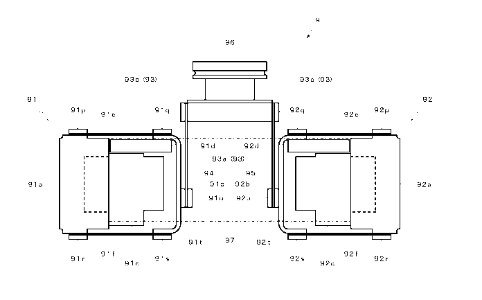
[0030] Referring to FIGS. 4 and 5, the schematic configuration
of the vibration unit 9 will be described.
As shown in FIGS. 4 and 5, the vibration unit 9 includes
a pair of vibration portions 91 and 92, a movable portion 93,
a pair of plate springs 94 and 95, an attachment bracket 96,
and a pair of weights 97.
[0031] The vibration portion 91 has a fixed frame 91a, a movable
frame 91b, an electromagnet 91c, an armature 91d, two plate
springs 91e and 91f, and six plate spring retainers 91p to 91u.
[0032] The fixed frame 91a is a block member substantially in
the shape of a trapezoid. The movable frame 91b is a block
member substantially in the shape of a U.
[0033] The electromagnet 91c is attached to the inner wall of
the fixed frame 91a. The armature 91d is attached to the upper
7
CA 02980429 2017-09-20
inner wall of the movable frame 91b.
[0034] Each of the two plate springs 91e and 91f is arranged
spanning between the fixed frame 91a and the movable frame 91b.
Specifically, one end of the plate spring 91e is fixed to the
fixed frame 91a in a state of being held between the upper face
of the fixed frame 91a and the plate spring retainer 91p. The
other end of the plate spring 91e is fixed to the movable frame
91b in a state of being held between the upper face of the movable
frame 91b and the plate spring retainer 91q.
[0035] One end of the plate spring 91f is fixed to the fixed
frame 91a in a state of being held between the lower face of
the fixed frame 91a and the plate spring retainer 91r. The other
end of the plate spring 91f is fixed to the movable frame 91b
in a state of being held between the lower face of the movable
frame 91b and the plate spring retainer 91s.
[0036] The vibration portion 92 has a fixed frame 92a, a movable
frame 92b, an electromagnet 92c, an armature 92d, two plate
springs 92e and 92f, and six plate spring retainers 92p to 92u.
[0037] The fixed frame 92a is a block member substantially in
the shape of a trapezoid. The movable frame 92b is a block
member substantially in the shape of a U.
[0038] The electromagnet 92c is attached to the inner wall of
the fixed frame 92a. The armature 92d is attached to the upper
inner wall of the movable frame 92b.
[0039] Each of the two plate springs 92e and 92f is arranged
spanning between the fixed frame 92a and the movable frame 92b.
Specifically, one end of the plate spring 92e is fixed to the
8
CA 02980429 2017-09-20
fixed frame 92a in a state of being held between the upper face
of the fixed frame 92a and the plate spring retainer 92p. The
other end of the plate spring 92e is fixed to the movable frame
92b in a state of being held between the upper face of the movable
frame 92b and the plate spring retainer 92q.
[0040] One end of the plate spring 92f is fixed to the fixed
frame 92a in a state of being held between the lower face of
the fixed frame 92a and the plate spring retainer 92r. The other
end of the plate spring 92f is fixed to the movable frame 92b
in a state of being held between the lower face of the movable
frame 92b and the plate spring retainer 92s.
[0041] The movable portion 93 has an attachment frame 93a and
two plate spring retainers 93b and 93c.
[0042] The plate spring 94 is arranged spanning between the
movable frame 91b and the movable portion 93. Specifically,
the lower end of the plate spring 94 is fixed to the movable
frame 91b in a state of being held between the plate spring
retainer 91t fixed to the outer wall face of the movable frame
91b and the plate spring retainer 91u facing the plate spring
retainer 91t. The upper end of the plate spring 94 is fixed
to the attachment frame 93a in a state of being held between
the outer wall face of the attachment frame 93a of the movable
portion 93 and the plate spring retainer 93b.
[0043] The plate spring 95 is arranged spanning between the
movable frame 92b and the movable portion 93. Specifically,
the lower end of the plate spring 95 is fixed to the movable
frame 92b in a state of being held between the plate spring
9
CA 02980429 2017-09-20
retainer 92t fixed to the outer wall face of the movable frame
92b and the plate spring retainer 92u facing the plate spring
retainer 92t. The upper end of the plate spring 95 is fixed
to the attachment frame 93a in a state of being held between
the outer wall face of the attachment frame 93a of the movable
portion 93 and the plate spring retainer 93c.
[0044] The attachment bracket 96 is arranged on the upper face
of the attachment frame 93a of the movable portion 93.
The dispersion table 2 is attached to the attachment
bracket 96.
[0045] The weights 97 are arranged spanning between the fixed
frame 91a of the vibration portion 91 and the fixed frame 92a
of the vibration portion 92.
[0046] Referring to FIG. 4, an operation of the vibration unit
9 will be described.
When the electromagnet 91c of the vibration portion 91
is driven, the armature 91d is attracted to the electromagnet
91c, and thus the movable frame 91b is moved downward, and the
two plate springs 91e and 91f are deflected downward. When the
two plate springs 91e and 91f are deflected downward, the
movable frame 91b is moved downward parallel to the fixed frame
91a.
[0047] In a similar manner, when the electromagnet 92c of the
vibration portion 92 is driven, the armature 92d is attracted
to the electromagnet 92c, and thus the movable frame 92b is moved
downward, and the two plate springs 92e and 92f are deflected
downward. When the two plate springs 92e and 92f are deflected
CA 02980429 2017-09-20
downward, the movable frame 92b is moved downward parallel to
the fixed frame 92a.
[0048] The pair of vibration portions 91 and 92 vibrate in the
same direction in synchronization with each other under the
control of the controller (not shown) . Accordingly, when the
electromagnets 91c and 92c are driven, the movable frames 91b
and 92b move away from each other while moving downward as
described above (perform a so-called arc motion) .
[0049] Accordingly, the pair of plate springs 94 and 95 attached
to the movable frames 91b and 92b are moved downward. As a
result, the attachment bracket 96 is also moved downward. At
this time, an increase in the distance between the movable
frames 91b and 92b is absorbed by the pair of plate springs 94
and 95 being deflected outward, and thus the attachment bracket
96 moves only downward. When the driving of the electromagnets
91c and 92c is repeatedly turned on/off, the attachment bracket
96 vibrates up and down together with the dispersion table 2.
[0050] With the thus configured dispersion table 2 and vibration
unit 9, articles loaded from above onto the center of the
dispersion table 2 slide down the first face 21a and move toward
the plurality of supply hoppers 4. At this time, since the
dispersion table 2 is vibrated up and down by the vibration unit
9, the articles on the dispersion table 2 are radially
dispersed.
[0051] Furthermore, since each of the second face 21b and the
third face 21c has an angle of inclination larger than that of
the first face 21a, articles positioned near the wall portion
11
CA 02980429 2017-09-20
22 slide down the second face 21b and the third face 21c and
move to the first face 21a.
[0052] As described above, according to this embodiment, the
dispersion table 2 is vibrated up and down by the vibration unit
9 having the pair of vibration portions 91 and 92, and thus the
load that acts on the vibration unit 9 can be suppressed even
when the size of the dispersion table 2 is increased, and
malfunctioning of or damage to the vibration unit 9 can be
prevented.
[0053] Furthermore, in this embodiment, when the movable frames
91b and 92b move away from each other while moving downward
(perform a so-called arc motion), an increase in the distance
between the movable frames 91b and 92b is suppressed by the pair
of plate springs 94 and 95 being deflected outward, and thus
only vibrations in the up-down direction are imparted to the
attachment bracket 96. As a result, only vibrations in the
up-down direction are imparted to the dispersion table 2 as well,
and thus unevenness in the dispersion of articles caused by
unevenness in the vibrations can be suppressed compared with
a case of a vibration unit including only one vibration portion
for generating vibrations up and down.
[0054] Furthermore, in this embodiment, in the table main body
21 of the dispersion table 2, the second face 21b and the third
face 21c each having an angle of inclination larger than that
of the first face 21a are located on the wall portion 22 side,
and thus the accumulation of articles on the wall portion 22
side can be suppressed.
12
CA 02980429 2017-09-20
[0055] Above, an embodiment of the present invention has been
described, but the invention is not limited thereto, and various
modifications can be made within the scope not departing from
the gist of the invention.
[0056] In the foregoing embodiment, the ridge 2f of the
dispersion table 2 extends in the horizontal direction, but
there is no limitation to this. That is to say, there is no
particular limitation on the angle of the ridge 2f as long as
the second face 21b and the third face 21c extending from the
ridge 2f are inclined downward so that the portion in contact
with the wall portion 22 is inclined downward. Accordingly,
the ridge 2f may be inclined upward or downward.
[0057] Furthermore, the ridge 2f does not have to be clear, and,
for example, it may be a line extending along the top of a curved
face.
[0058] The first face 21a, the second face 21b, and the third
face 21c may not be flat faces, and they may be curved faces
as long as they are inclined downward. Furthermore, the first
face 21a, the second face 21b, and the third face 21c may be
each configured by a combination of a plurality of flat faces
and curved faces instead of one face.
[0059] Furthermore, in the foregoing embodiment, the third
boundary 2g and the fourth boundary 2h are straight lines, but
there is no limitation to this, and they may be curved lines.
Accordingly, the wall portion 22 also may be a curved face.
[0060] Furthermore, in the foregoing embodiment, two
combination balances 100 may be arranged adjacent to each other
13
CA 02980429 2017-09-20
such that the wall portions 22 (non-discharge regions) provided
at the dispersion tables 2 face each other, thereby forming one
combination balance device having two combination balances 100.
[0061] Furthermore, the combination balance according to the
present invention can be applied to articles other than food.
Reference Signs List
[0062] 2 Dispersion table
21a First face
21b Second face
21c Third face
22 Wall portion
9 Vibration unit
91, 92 Vibration portion
91a, 92a Fixed frame
91b, 92b Movable frame
91c, 92c Electromagnet
91d, 92d Armature
91e, 92e Plate spring
91f, 92f Plate spring
93 Movable portion
94, 95 Plate spring
96 Attachment bracket
100 Combination balance
14