Note: Descriptions are shown in the official language in which they were submitted.
SKIRT SYSTEM MOUNT BRACKET ASSEMBLY
CROSS-REFERENCE TO RELATED APPLICATIONS
[0001] This application claims the benefit of U.S. Provisional
Application Serial No.
62/402,234, filed on September 30, 2016, and entitled "Skirt System Mount
Bracket Assembly".
BACKGROUND
[0002] To reduce wind flow resistance and drag on a semi-trailer truck,
trailer, a pup
trailer, tractor, semitrailer, or other vehicle, aerodynamic devices may be
used to redirect and
control the flow of air passing around the vehicle. During operation of a
tractor-trailer truck, air
around the tractor-trailer truck may flow between the tractor unit and the
trailer, or underneath
the trailer, and impart a drag force to the trailer. Aerodynamic devices are
designed to control the
air flowing into the gap formed between the tractor unit and the trailer and
underneath the tractor
and trailer. Such reduction on the drag of the vehicle may conserve fossil
fuels, as well as other
sources of vehicle drive power for hybrid vehicles, battery-operated vehicles,
and alternative
fuel-based vehicles, for example.
SUMMARY
[0003] The present disclosure may comprise one or more of the following
features and
combinations thereof
[0004] According to one embodiment of the present disclosure, a mount
bracket
assembly for a skirt system of a trailer is provided. The mount bracket
assembly includes a
1
CA 2980861 2017-09-29
i
,
channel mount configured to be coupled to a portion of the skirt system and an
attachment
assembly configured to be coupled to a flange of a cross-member of the
trailer. The attachment
assembly includes a top wall coupled to the channel mount and a mounting
bracket fixed to the
top wall. The mounting bracket includes two hook-shaped portions separated by
a planar portion,
wherein the two hook-shaped portions are each sized to fit over the flange.
[0005] In some embodiments, the mounting bracket is fixed at an
angle with respect to
the top wall, the angle being selected from the group consisting of 0 degrees,
+13.8 degrees, and
-13.8 degrees.
[0006] In some embodiments, the mounting bracket is fixed by
welding to the top wall.
[0007] In some embodiments, the mounting bracket includes a
first aperture and a second
aperture, the top wall includes a third aperture and a fourth aperture, a
first fastener is inserted
through the first and third apertures, and a second fastener is inserted
through the second and
fourth apertures.
[0008] In some embodiments, the fourth aperture is formed as an
opening to allow the
second fastener to be positioned at one of at least three locations within the
opening to change an
angle of the mount bracket assembly.
[0009] In some embodiments, the opening provides for the angle
to be between about 3
and about 30 degrees.
[0010] In some embodiments, a toe clamp positioned above the
mounting bracket and
configured to clamp a second flange of the cross-member.
[0011] In some embodiments, the mounting bracket includes a
first aperture and a second
aperture, the top wall includes a third aperture and a fourth aperture, the
toe clamp includes a
fifth aperture and a sixth aperture, a first fastener is inserted through the
first, third, and fifth
2
CA 2980861 2017-09-29
apertures, and a second fastener is inserted through the second, fourth, and
sixth apertures.
[0012] In some embodiments, the mount bracket assembly further including
an upper
plate positioned above the toe clamp and further including seventh and eighth
apertures through
which the first and second fasteners extend, respectively.
[0013] According to another embodiment, a mount bracket assembly for a
skirt system of
a trailer is provided. The mount bracket assembly includes a channel mount
configured to be
coupled to the skirt system and an attachment assembly configured to attach
the channel mount
to the trailer. The attachment assembly includes a top wall coupled to the
channel mount and
including a first set of apertures therethrough, a mounting bracket fixed to
the top wall at an
angle and including a second set of apertures therethrough, a toe clamp
including a third set of
apertures therethrough, and an upper plate including a fourth set of apertures
therethrough. Bolts
are configured to be received through the first, second, third, and fourth
sets of apertures when
the first, second, third, and fourth sets of apertures are aligned and nuts
configured to be
tightened over each of the bolts to couple together the top wall, the mounting
bracket, the toe
clamp, and the upper plate.
[0014] In some embodiments, the angle is selected from the group
consisting of 0
degrees, +13.8 degrees, and -13.8 degrees.
[0015] In some embodiments, at least one of the apertures of the top wall
is formed as an
opening to allow the bolt positioned therein to be positioned at one of at
least three locations
within the opening to change an angle of the mount bracket assembly.
[0016] In some embodiments, the opening provides for the angle to be
between about 3
and about 30 degrees.
3
CA 2980861 2017-09-29
[0017] In some embodiments, the opening provides for the angle to be
between about 10
and about 20 degrees.
[0018] According to yet another embodiment, a method for assembling a
mount bracket
assembly for a skirt system of a trailer is provided. The method includes
providing a channel
mount, a top wall with a first set of apertures, and a mounting bracket with a
second set of
apertures. The method also includes coupling the top wall to the channel
mount, aligning the first
set of apertures with the second set of apertures, and welding together the
top wall and the
mounting bracket.
[0019] In some embodiments, the top wall and the mounting bracket are
welded together
at a fixed angle selected from the group consisting of 0 degrees, +13.8
degrees, and -13.8
degrees.
[0020] In some embodiments, the providing step further includes providing
a toe clamp
with a third set of apertures and the aligning step further includes aligning
the first, second, and
third sets of apertures.
100211 In some embodiments, the providing step further includes providing
an upper
plate with a fourth set of apertures, the aligning step further includes
aligning the first, second,
third, and fourth sets of apertures, and the method further includes the step
of positioning the toe
clamp above the mounting bracket and positioning the upper plate above the toe
clamp.
[0022] In some embodiments, the method further includes the step of
attaching the mount
bracket assembly to a flange of a cross-member of the trailer by hooking a
first of two hook
portions of the channel mount around a first flange member of the flange and
clamping a second
flange member of the flange between the channel mount and the toe clamp.
4
CA 2980861 2017-09-29
[0023] In some embodiments, one of the apertures of the first set of
apertures forms a
channel to provide a varied alignment of the first and second sets of
apertures to vary an angle
between the top wall and the channel mount.
[0024] These and other features of the present disclosure will become
more apparent
from the following description of the illustrative embodiments.
BRIEF DESCRIPTION OF THE DRAWINGS
[0025] FIG. 1 is a top perspective view of a tractor and two pup trailers
with skirt
assemblies that may be secured to the trailers using any of the mount bracket
assemblies
described herein;
[0026] FIG. 2 is a top perspective view of a trailer with another skirt
assembly that may
be secured to the trailer using any of the mount bracket assemblies described
herein;
100271 FIG. 3A is a side elevation view of an interior of a landing gear
skirt and a side
skirt of the skirt assembly of FIG. 2;
100281 FIG. 3B is a side elevation view of an interior of a rear wheel
assembly skirt and a
rear skirt of the skirt assembly of FIG. 2;
[0029] FIG. 4 is a perspective view of a tractor and a trailer with a
further skirt assembly
that may be secured to the trailer using any of the mount bracket assemblies
described herein;
[0030] FIG. 5 is a top perspective view of the skirt assembly and a floor
of the trailer of
FIG. 4;
[0031] FIG. 6A is a side elevation view of a landing gear skirt of the
skirt assembly of
FIG. 4 and a rigid dual-hook mount bracket assembly for attaching the landing
gear skirt to the
trailer;
CA 2980861 2017-09-29
[0032] FIG. 6B is a side elevation view of a side skirt of the skirt
assembly of FIG. 4 and
a spring-based mount bracket assembly for attaching the side skirt to the
trailer;
[0033] FIG. 6C is a side elevation view of a rear skirt of the skirt
assembly of FIG. 4 and
a rigid mount bracket assembly for attaching the rear skirt to the trailer;
[0034] FIG. 7 is a top plan view of the skirt assembly and the floor of
the trailer of
FIG. 4, including the mount bracket assemblies of FIGS. 6A-6C;
[0035] FIG. 8A is a top perspective view of the rigid dual-hook mount
bracket assembly
of FIG. 6A;
100361 FIG. 8B is an exploded top perspective view of the rigid dual-hook
mount bracket
assembly of FIG. 6A;
[0037] FIG. 8C is a top plan view of a top wall of the rigid dual-hook
mount bracket
assembly of FIG. 6A;
[0038] FIG. 9 is a partial cutaway view of the rigid dual-hook mount
bracket assembly of
FIG. 6A coupled to a trailer floor; and
[0039] FIG. 10 is an underside view of two rigid dual-hook mount bracket
assemblies of
FIG. 6A coupled to a trailer floor.
DETAILED DESCRIPTION
100401 Before any embodiments of the invention are explained in detail,
it is to be
understood that the invention is not limited in its application to the details
of construction and the
arrangement of components set forth in the following description or
illustrated in the following
drawings. The invention is capable of other embodiments and of being practiced
or of being
carried out in various ways. Also, it is to be understood that the phraseology
and terminology
6
CA 2980861 2017-09-29
used herein is for the purpose of description and should not be regarded as
limiting. The use of
"including," "comprising," or "having" and variations thereof herein is meant
to encompass the
items listed thereafter and equivalents thereof as well as additional items.
Unless specified or
limited otherwise, the terms "mounted," "connected," "supported," and
"coupled" and variations
thereof are used broadly and encompass both direct and indirect mountings,
connections,
supports, and couplings. Further, "connected" and "coupled" are not restricted
to physical or
mechanical connections or couplings.
100411 The following discussion is presented to enable a person skilled
in the art to make
and use embodiments of the invention. Various modifications to the illustrated
embodiments
will be readily apparent to those skilled in the art, and the generic
principles herein can be
applied to other embodiments and applications without departing from
embodiments of the
invention. Thus, embodiments of the invention are not intended to be limited
to embodiments
shown, but are to be accorded the widest scope consistent with the principles
and features
disclosed herein. The following detailed description is to be read with
reference to the figures, in
which like elements in different figures have like reference numerals. The
figures, which are not
necessarily to scale, depict selected embodiments and are not intended to
limit the scope of
embodiments of the invention. Skilled artisans will recognize the examples
provided herein have
many useful alternatives and fall within the scope of embodiments of the
invention.
100421 For the purposes of promoting an understanding of the principles
of the invention,
reference will now be made to a number of illustrative embodiments shown in
the attached
drawings and specific language will be used to describe the same. While the
concepts of this
disclosure are described in relation to a trailer for a tractor, it will be
understood that that they are
equally applicable to other trailers generally, and more specifically to pup
trailers, conventional
7
CA 2980861 2017-09-29
flat-bed and/or box or van type trailers, examples of which include, but
should not be limited to,
straight truck bodies, small personal and/or commercial trailers and the like.
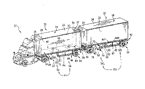
[0043] A tractor 10 can be coupled to one or more trailers 12 for
transporting goods
along a roadway, as shown in FIG. 1. Each trailer 12 may generally include a
container 14, a
floor 16, a rear wheel assembly 18, a landing gear 20, and a skirt system 22.
The skirt system 22
is coupled to the floor 16 and is configured to redirect air and improve fuel
efficiency of the
tractor 10 when transporting goods.
[0044] As shown in FIG. 1, the container 14 of the trailer 12 can have a
roof 24, a front
wall 26, a left wall 28, a right wall 30, and a rear frame assembly 32. The
rear frame assembly 32
can include a rear frame and one or more doors 34, for example, swing doors or
an overhead
door, to allow access to the interior of the container 14.
[0045] The floor 16 of the trailer 12 has a front side 36, a left side
38, a right side 40, a
back side 42, and a plurality of cross-members 92 extending from the left side
38 to the right side
40, as shown in FIG. 1. The floor 16 is included in an embodiment of trailer
12 in which the
floor 16 supports the container 14. Alternatively, the trailer 12 may be a
flat-bed trailer that does
not include the container 14.
[0046] The rear wheel assembly 18 is coupled to the floor 16 near the
back side 42 of the
floor 16, as shown in FIG. 1. The rear wheel assembly 18 includes wheels 44
and an axle 46 that
support the rear of the trailer 12 when the trailer 12 is being pulled by the
tractor 10, and when
the trailer 12 is stationary and disconnected from the tractor 10.
[0047] The landing gear 20 is coupled to the floor 16 between the rear
wheel assembly
18 and the front side 36 of the floor 16, as shown in FIG. 1. The landing gear
20 includes at least
one support leg 48, a crank handle 50, and may contain a landing gear foot 52.
The support leg
8
CA 2980861 2017-09-29
,
48 can extend down from the floor 16 to a surface to support the trailer 12
when not connected to
the tractor 10, or can be retracted when connected to the tractor 10. The
support leg 48 of the
landing gear 20 can be extended or retracted using the crank handle 50.
[0048] While the principles of the present invention are depicted as
being utilized with
respect to particular vehicles (i.e., trailers) and with particular skirt
systems, one skilled in the art
will recognize that the principles of the present invention may be utilized
for attachment of any
skirt system or aerodynamic device to any type of vehicle.
[0049] To improve the air flow and fuel efficiency of the tractor 10
when pulling a trailer
12, the trailer 12 can include an aerodynamic skirt system 22, as shown in
FIG. 1. Skirt systems
can include any combination of a landing gear skirt, a side skirt, a rear
wheel assembly skirt, and
a rear skirt. In an illustrative embodiment, as shown in FIG. 1, a skirt
system 22 includes a
landing gear skirt 54 and side skirt 56. In another illustrative embodiment,
as shown in FIG. 2, a
skirt system 222 of a trailer 212 includes a landing gear skirt 254, a side
skirt 256, a rear wheel
assembly skirt 258, and a rear skirt 260. In yet another illustrative
embodiment, as shown in
FIG. 4, a skirt system 322 of a trailer 312 includes a landing gear skirt 354,
a side skirt 356, and
a rear skirt 360. The trailers 212 and 312 generally include similar parts
corresponding to those
discussed above with respect to the trailer 12.
[0050] Generally, the skirt system 22 can be coupled to the trailer 12
along the left side
38 or the right side 40 of the floor 16, or both the left side 38 and the
right side 40, as shown in
FIG. I. The skirt system 22 is attached to the left side 38 and/or the right
side 40 of the floor 16
with mount bracket assemblies 62. Attaching the skirt system 22 with the mount
bracket
assemblies 62 can allow the skirt system 22 to tilt if contacted by an object
to reduce stress on
the skirt system 22 or the object. More specifically, the mount bracket
assemblies 62 can allow
9
CA 2980861 2017-09-29
the skirt system 22 to tilt laterally both inwardly and outwardly relative to
the floor 16 (and,
more specifically, to the cross-members 92). The ability of the skirt system
22 to tilt bi-laterally
relative to a cross-member 92 (i.e., to tilt both inwardly and outwardly
relative to the cross-
member 92) allows the skirt system 22 to potentially avoid damage when the
trailer 12 traverses
into or over a fixed, immovable obstacle, for example, and thus runs laterally
into the obstacle. It
should also be understood, however, that the skirt system 22 may be
sufficiently rigidly mounted
to the floor such that the skirt system 22 is generally prevented from tilting
under normal wind
and road air forces.
[0051] The landing gear skirt 54 of the skirt system 22 may improve fuel
economy by
deflecting air away from the front side 36 of the trailer 12 and allowing air
flow to attach to the
side skirt 56 quicker. More specifically, the landing gear skirt 54 can help
guide air from beneath
the tractor 10 (and off of tires of the tractor 10) onto the side skirt 56. As
shown in FIG. 1, the
landing gear skirt 54 is coupled to the floor 16 of the trailer 12 and
includes a wall panel 64 and a
flexible bottom flap 66. The flexible bottom flap 66 is configured to attach
to the wall panel 64
and provides a protective edge, as discussed below.
[0052] The wall panel 64 of the landing gear skirt 54 can be made from a
composite
material, or from a metal. For example, the composite material may include a
plastic core and
metal outer skins coupled to the plastic core. Such a composite material
provides a rigid but
lightweight and durable material. For example, each wall panel 64 may be made
of a
DURAPLATE composite panel provided by Wabash National Corporation of
Lafayette, Ind.
DURAPLATE composite panels are constructed of a high-density polyethylene
plastic core
bonded between two high-strength steel skins. For another example, the wall
panel 64 can be
made of a glass reinforced thermoplastic composite. It should be understood
that other suitable
CA 2980861 2017-09-29
composite materials may be used as well. Further, the wall panel 64 may be of
any number of
suitable, non-composite materials such as metals, metal alloys, and/or
plastics, for example.
100531 The flexible bottom flap 66 extends downwardly from the wall panel
64 to
provide a less stiff strip along a bottom side 72 of the wall panel 64, as
shown in FIG. 1. In some
embodiments, the flexible bottom flap 66 is configured to be coupled to the
bottom side 72 of the
wall panel 64 along the entire length of wall panel 64. Illustratively, the
flexible bottom flap 66
is made of plastic or rubber. However, other suitable materials may be used as
well. The flexible
bottom flap 66 further operates to resist airflow and may prevent damage to
the wall panel 64
from forces applied vertically, such as in situations where the trailer 12 may
traverse over a curb
or railroad track where the road surface is not flat. In such instances, for
example, the flexible
bottom flap 66 is configured to bend or flex to prevent damage to the wall
panel 64. In some
embodiments, however, the wall panel 64 may not include a flexible bottom flap
66.
100541 Additionally, the wall panel 64 can be formed to include an
aperture 76 sized to
allow passage of the landing gear crank handle 50, as shown in FIG. 1. The
aperture 76 may be
arranged along a top side of the wall panel 64 adjacent to the floor 16 of the
trailer 12. The
aperture 76 may be included in the right landing gear skirt 54R (not shown) or
the left landing
gear skirt 54L, or may be included in both the left landing gear skirt 54L and
the right landing
gear skirt 54R. In some embodiments, the aperture 76 may not be included
either in the left
landing gear skirt 54L or the right landing gear skirt 54R.
100551 The landing gear skirt 54 can be coupled to the floor 16 of the
trailer 12 as to be
parallel with either the left side 38 or the right side 40 of the floor 16.
Alternatively, the landing
gear skirt 54 can be non-parallel with the either the left side 38 or the
right side 40 of floor 16, as
shown in FIG. 1. Illustratively, the left landing gear skirt 54L has a front
edge 78 facing the front
11
CA 2980861 2017-09-29
side 36 of the floor 16 and a back edge 80 facing the back side 42 of the
floor 16. The left
landing gear skirt 54L can be angled relative to the floor 16 so that front
edge 78 is closer to the
right side 40 of the floor 16 than the back edge 80. Orienting the landing
gear skirt 54 in such a
manner may lead to improved uptake of the air flow from underneath the trailer
12.
[0056] The skirt system 22 also includes a left side skirt 56L, as shown
in FIG. 1, and a
right side skirt 56R (not shown). The left side skirt 56L extends downwardly
from and is located
along the left side 38 of the floor 16 between the left landing gear skirt 54L
and the rear wheel
assembly 18. Similarly, the right side skirt 56R extends downwardly from and
is located along
the right side 40 of the floor 16 between the right landing gear skirt 54R and
the rear wheel
assembly 18. It should be understood that the trailer 12 has both a right
skirt system 22R and a
left skirt system 22L that are identical in configuration and function, even
if only a single side is
being described.
[0057] As shown in FIG. 1, the side skirt 56 includes two wall panels 84
coupled to each
other and a flexible bottom flap 85. The wall panels 84 are secured to each
other and to the trailer
12 by mount bracket assemblies 62. Illustratively, a first mount bracket
assembly 62 is
positioned to couple the forward wall panel 84F to the floor 16. A second
mount bracket
assembly 62 is positioned between and coupled to the forward wall panel 84F
and the rear wall
panel 84R to couple the two wall panels 84F, 84R to each other and to the
floor 16. A third
mount bracket assembly 62 is coupled to the rear wall panel 84R to secure the
wall panel 84R to
the floor 16. Illustratively, while the side skirt 56 includes three mount
bracket assemblies 62 and
two wall panels 84F, 84R, it is within the scope of this disclosure to provide
a side skirt 56
having any number of mount bracket assemblies 62 and any number of wall panels
84. Further, it
is within the scope of this disclosure for the side skirt 22 to include a
single, unitary wall panel
12
CA 2980861 2017-09-29
84. The flexible bottom flap 85 of the side skirt 56 is similar to the
flexible bottom flap 66 of the
landing gear skirt 54. Illustratively, the wall panels 84F and 84R can each
have a flexible bottom
flap 85 coupled by a bracket 87, or alternatively can share a single flexible
bottom flap 85. Also,
in some embodiments, the wall panels 84F, 84R may not include a flexible
bottom flap 85.
[0058] In another embodiment, a skirt system 222 includes a continuously
connected
landing gear skirt 254, a side skirt 256, a rear wheel assembly skirt 258, and
a rear skirt 260, as
shown in FIG. 2. The skirt system 222 can be coupled to a floor 216 of a
trailer 212 using mount
bracket assemblies 62, 262.
[0059] Illustratively, the landing gear skirt 254 includes an aperture
276 that is sized for a
crank handle (not shown), three wall panels 264, mount bracket assemblies 62
to couple the wall
panels 264 to each other and to the floor 216, and a single flexible bottom
flap 266, as shown in
FIGS. 2-3A. The wall panels 264 and the flexible bottom flap 266 of the
landing gear skirt 254
are similar to the above-described corresponding parts of the landing gear
skirt 54. However, in
some embodiments, the wall panels 264 may not include a flexible bottom flap
266.
Furthermore, the landing gear skirt 254 can be coupled to the side skirt 256
by mount bracket
assemblies 62 to form a continuously connected skirt system 222, as shown in
FIGS. 2-3A.
[0060] The side skirt 256 includes wall panels 284, mount bracket
assemblies 62 that
connect the wall panels 284 to the floor 216, and flexible bottom flaps 285.
Illustratively, the
side skirt 256 can have two wall panels 284F, 284R coupled to each other, as
shown in FIG. 3A.
The wall panels 284F, 284R are secured to each other and to the trailer 212 by
mount bracket
assemblies 62 in a similar fashion to the above-described side skirt 56. More
specifically, a first
mount bracket assembly 62 is positioned to couple the forward wall panel 284F
to the floor 216
and to the landing gear skirt 254. A second mount bracket assembly 62 is
positioned between
13
CA 2980861 2017-09-29
and coupled to the forward and the rear wall panels 284F, 284R to couple the
two wall panels
284F, 284R to each other and to the floor 216. A third mount bracket assembly
62 is coupled to
the rear wall panel 284R to secure the wall panel 284R to the floor 216.
Illustratively, while the
side skirt 256 includes three mount bracket assemblies 62 and two wall panels
284, it is within
the scope of this disclosure to provide a side skirt 256 having any number of
mount bracket
assemblies 62 and any number of wall panels 284.
[0061] The rear wheel assembly skirt 258 includes wall panels 286, mount
bracket
assemblies 262 for coupling the wall panels 286 to the floor 216, and bottom
strips 288, as
shown in FIGS. 2 and 3B. The rear wheel assembly skirt 258 extends downwardly
from the floor
216 and is positioned along the left side 238 or the right side 240 of the
floor 216. Illustratively,
the rear wheel assembly skirt 258 is located between the back side 242 of the
floor 216 and the
side skirt 256, and locates the rear wheel assembly 218 within a footprint of
the left wheel
assembly skirt 258L and the right wheel assembly skirt 258R (not shown) when
the trailer 212 is
viewed from the left side or the right side of the trailer 212. In some
embodiments, the rear wheel
assembly skirt 258 extends all the way to the back side 242 of the floor 216.
Also, the rear wheel
assembly skirt 258 can be coupled to the side skirt 256 or may not be coupled
to side skirt 256.
[0062] As shown in FIG. 3B, the rear wheel assembly skirt 258 can have
two wall panels
286F, 286R coupled to each other. The wall panels 286F, 286R are secured to
each other and to
the trailer 212 by mount bracket assemblies 262. Illustratively, a first mount
bracket assembly
262 is positioned to couple the forward wall panel 286F to the floor 216 and
is comprised of a
stiff metal plate. A second mount bracket assembly 262 is positioned between
and coupled to the
forward and the rear wall panels 286F, 286R to couple the two wall panels
286F, 286R to each
other and to the floor 216. A third mount bracket assembly 262 is coupled to
the rear wall panel
14
CA 2980861 2017-09-29
286R to secure the rear wall panel 286R to the floor 216 and optionally to the
rear skirt 260, as
shown in FIG. 3B.
100631 The rear wheel assembly skirt 258 further includes hinges 290 and
tethers 292
that couple the wall panels 286 to the floor 216, as shown in FIGS. 2 and 3B.
The hinges 290
allow pivoting of the wall panels 286 relative to the floor 216, while the
tethers 292 provide an
additional attachment point of the wall panels 286 to the floor 216. Also, the
bottom strip 288 is
similar in composition and function to the flexible bottom flaps 266, 285 of
the landing gear skirt
254 and the side skirt 256, respectively. Illustratively, while the rear wheel
assembly skirt 258
includes three mount bracket assemblies 262 and two wall panels 286F, 286R, it
is within the
scope of this disclosure to provide a rear wheel assembly skirt 258 having any
number of mount
bracket assemblies 262 and any number of wall panels 286.
100641 The rear skirt 260 includes a wall panel 294, mount bracket
assemblies 262 for
coupling the wall panel 294 to the floor 216, and a bottom strip 296, as shown
in FIGS. 2 and
3B. The rear skirt 260 extends downwardly from the floor 216, along the left
side 238 or the
right side 240 of the floor 216, and is located between the back side 242 of
the floor 216 and the
rear wheel assembly skirt 258. Illustratively, the rear skirt 260 can be
coupled to the rear wheel
assembly skirt 258 with a mount bracket assembly 262.
[00651 The wall panel 294 of the rear skirt 260 includes a forward edge
298 and a rear
edge 299, as shown in FIG. 3B. Illustratively, the forward edge 298 extends
down from the floor
216 and is generally perpendicular to floor 216, and the rear edge 299 can be
straight or curved
to provide additional aerodynamic properties to the trailer 212.
100661 According to another embodiment, a skirt system 322 includes a
landing gear
skirt 354, a side skirt 356, and a rear skirt 360, as shown in FIGS. 4 and 5.
The skirt system 322
CA 2980861 2017-09-29
can be coupled to a floor 316 of a trailer 312 using mount bracket assemblies
362 to improve the
airflow around the trailer 312.
[0067] Illustratively, the landing gear skirt 354 is sized to permit
clearance for a crank
handle 350 between the landing gear skirt 354 and the side skirt 356, as shown
in FIG. 5. The
landing gear skirt 354 includes a wall panel 364 and mount bracket assemblies
362 to couple the
wall panel 364 to the floor 316. The wall panel 364 includes top, middle, and
bottom horizontal
ribs 368 that project outwardly away from the trailer 312 and that are
separated by generally
planar portions 370, as shown in FIGS. 6A-6C. The ribs 368 are provided to
increase the
stiffness of the wall panel 364. While three sets of ribs 368 are provided, it
should be understood
that the wall panel 364 may be configured to include any number of suitable
ribs, or no ribs at
all, in order to modify the stiffness of the wall panel 364 to that of a
specifically desired level. It
should also be understood that the wall panel 364 may also, or alternatively,
include ribs 368
which project inwardly. Further, while the illustrative ribs 368 are
horizontal, it should be
understood that the wall panels disclosed herein may include ribs which are
vertical, curved,
and/or diagonal, for example. Additionally, in some embodiments, the wall
panel 364 can further
include a flexible flap (not shown) similar to the flap 66 of the landing gear
skirt 56.
[0068] The landing gear skirt 354 can be coupled to the floor 316 as to
be parallel with
either the left side 338 or the right side 340 of the floor 316 of the trailer
312. Alternatively, the
landing gear skirt 354 can be non-parallel with the either the right side 340
or the left side 338 of
floor 316. For example, the left landing gear skirt 354L has a front edge 378L
facing the front
side 336 of the floor 316, a back edge 380L facing the back side 342 of the
floor 316, a top edge
377 facing toward the floor 316, and a bottom edge 379 facing away from the
floor 316, as
shown in FIG. 6A. The left landing gear skirt 354L is angled relative to the
floor 316 so that
16
CA 2980861 2017-09-29
front edge 378L is closer to the right side 340 of the floor 316 than the back
edge 380L, as
shown in FIG. 7. Orienting the landing gear skirt 354 in this non-parallel
manner may lead to
improved uptake of air flow from underneath the tractor 310 and/or the trailer
312.
[0069] Additionally, the top and bottom edges 377, 379 of the landing
gear skirt 354 are
generally parallel to each other and define generally straight, horizontal
lines, while the front and
rear edges 378, 380 are generally V-shaped. Illustratively, the point of the V-
shaped edges 378,
380 is located at the center of the wall panel 364 and is aligned with the
middle rib 368 of the
wall panel 364, as shown in FIG. 6A. Further, the point of the V-shaped edges
378, 380 is
positioned forward of the top and bottom ends of the respective front and rear
edges 378, 380.
While the particular edges 378, 380 of the wall panel 364 disclosed herein are
V-shaped, it
should be understood that it is within the scope of this disclosure to include
front and rear edges
378, 380 as well as top and bottom edges 377, 379 which are straight, curved,
angled, and/or
combinations of each.
[0070] The side skirt 356 includes wall panels 384 and mount bracket
assemblies 362
that couple the wall panels 384 to the floor 316, as shown in FIGS. 4-5.
Illustratively, the side
skirt 356 can have three wall panels 384F, 384M, 384R separated horizontally
from each other,
as shown in FIGS. 4, 5, and 6B. The wall panels 384F, 384M, 384R can be
secured to the trailer
312 by the mount bracket assemblies 362 in a similar fashion to that described
above with
respect to the side skirt 56. More specifically, a first mount bracket
assembly 362 and a second
mount bracket assembly 362 are positioned at front and rear ends of the
forward wall panel 384F
to couple the forward wall panel 384F to the floor 316, as shown in FIG. 5. A
third mount
bracket assembly 362 and a fourth mount bracket assembly 362 are positioned at
front and rear
ends of the middle wall panel 384M to couple the middle wall panel 384M to the
floor 316. A
17
CA 2980861 2017-09-29
fifth mount bracket assembly 362 and a sixth mount bracket assembly 362 are
positioned at front
and rear ends of the rear wall panel 384R to couple the rear wall panel 384R
to the floor 316.
Illustratively, while the side skirt 356 includes six mount bracket assemblies
362 and three wall
panels 384F, 384M, 384R, it is within the scope of this disclosure to provide
a side skirt 356
having any number of mount bracket assemblies 362 and any number of wall
panels 384.
[0071] The wall panels 384F, 384M, 384R can include ribs 368 that project
outwardly
away from the trailer 312 and can be similar in shape and composition as the
wall panel 364 of
the landing great skirt 354. For example, the wall panels 384 can include V-
shaped front and rear
edges 381, 383. As shown in FIGS. 4 and 6B, the wall panels 384F, 384M, 384R
can be
horizontally spaced apart from each other and from the wall panel 364 of the
landing gear skirt
354. As a result, the V-shaped edges 378, 380, 381, 383 of adjacent panels
364, 384 cooperate to
defme generally V-shaped, horizontally-extending gaps, or spaces, 382 between
adjacent wall
panels 364, 384.
[0072] The wall panels 364, 384 can be sized and positioned relative to
each other to
create an air curtain over the gaps 382 so that air deflected from the first
wall panel 364 is
deflected over the gap 382 and to the second wall panel 384F, and so on.
Illustratively, the gaps
382 between each wall panel 364, 384 operate to allow airflow from under the
floor 316 (which
may cause additional drag against the rear wheel assembly 318) to escape, or
vent, out from
under the trailer 312, particularly in situations where cross-winds across the
trailer 312 are
present. While the side skirt 356 includes wall panels 384F, 384M, 384R
separated by gaps 382,
it is within the scope of this disclosure to provide a side skirt 356 having
adjacent wall panels
384 secured together by mount bracket assemblies 362 similar to the above-
described wall panel
18
CA 2980861 2017-09-29
84 and the mount bracket assembly 62. Additionally, in some embodiments, the
wall panel 384
can further include a flexible flap (not shown) similar to the flap 85 of side
skirt 56.
[0073] The rear skirt 360 includes a wall panel 386 and mount bracket
assemblies 362 for
coupling the wall panel 386 to the floor 316, as shown in FIGS. 4-5. The rear
skirt 360 extends
downwardly from the floor 316 and along the left side 338 or the right side
340 of the floor 316
and is located between the back side 342 of the floor 316 and the rear wheel
assembly 318.
Illustratively, a first mount bracket assembly 362 and a second mount bracket
assembly 362 are
positioned at front and rear ends of the wall panel 386 to couple the wall
panel 386 to the floor
316, as shown in FIGS. 5 and 6C.
[0074] The wall panel 386 can include ribs 368 that project outwardly
away from the
trailer 312 and can be similar in composition as the wall panel 364 of the
landing gear skirt 354.
Also, the wall panel 386 of the rear skirt 360 includes a forward edge 388 and
a rear edge 390, as
shown in FIG. 6C. Illustratively, the forward edge 388 extends down from the
floor 316 and is
generally perpendicular to the floor 316, and the rear edge 390 can be curved
to provide
additional aerodynamic properties to the trailer 312.
[0075] It is within the scope of this disclosure to provide a skirt
assembly wherein any
suitable number or type of the same or different mount bracket assemblies are
used to couple the
panels to the floor 316 of the trailer 312. As shown in FIGS. 5-7, the skirt
system 322 can
include one or more rigid dual-hook mount bracket assemblies 362A configured
to couple the
wall panel 364 to the floor 316, one or more spring-based mount bracket
assemblies 362B
configured to couple wall panels 384 to the floor 316, and/or one or more
rigid mount bracket
assemblies 362C configured to couple the wall panel 386 to the floor 316. Each
mount bracket
assembly 362 is coupled to a cross-member 392 of the floor 316. As further
discussed below, the
19
CA 2980861 2017-09-29
spring-based mount bracket assemblies 362B may permit the panels 384 to tilt
laterally with
respect to the cross-members 392, similar to mount bracket assembly 62 of FIG.
1, while the
mount bracket assemblies 362A, 362C rigidly mount the panels 364, 386 to the
floor 316 so that
the panels 364, 386 are prevented from tilting under normal wind and road air
forces. Despite the
generally rigid coupling, however, the wall panels 364, 386 can be made of
material that allows
the panels 364, 386 to flex and bend when impacted by, or traveling over, an
object in the path of
the wall panels 364, 386. The wall panels 364, 386 can then resiliently return
to their generally
vertical orientation after passing over such an object.
[0076] As described above, the wall panel 364 of the landing gear skirt
354 can be
coupled to the floor 316 using the rigid dual-hook mount bracket assembly 362A
shown in FIGS.
5-7. As shown in FIGS. 8A-8B, each rigid dual-hook mount bracket assembly 362A
generally
includes a channel mount 402 and an attachment assembly 403. The attachment
assembly 403
generally includes a top wall 404, a mounting bracket 406, a toe clamp 408, an
upper plate 410,
bolts 422, and nuts 434. The channel mount 402 is configured to be coupled to
the wall panel
364, and the attachment assembly 403 is configured to couple the mount bracket
assembly 362A
to the cross-member 392.
[0077] The channel mount 402 includes spaced-apart side walls 412, an
inside wall 414,
and side flanges 416 extending outwardly from outer edges of each of the side
walls 412.
Illustratively, the sidewalls 412 and the inside wall 414 cooperate to define
a passageway (not
shown) therebetween. Each side flange 416 includes a plurality of apertures
418 formed therein,
with each aperture 418 being configured to receive a fastener, such as a bolt,
rivet, screw or any
other suitable fastener (not shown), in order to couple the channel mount 402
to a wall panel 364.
CA 2980861 2017-09-29
[0078] The top wall 404 can be coupled to the channel mount 402 (for
example, via
welding) or, alternatively, can be otherwise attached or integral with the
channel mount 402. The
top wall 404 includes two apertures 420 (although any suitable number may be
utilized) each
configured to receive one of the threaded bolts 422 therethrough. As shown in
FIG. 8C, one of
the apertures 420 in the top wall 404 forms one or more openings (that may be
interconnected)
that define three (or another suitable number) locations for one of the bolts
422 to be positioned
therethrough. The three locations permit the rigid dual-hook mount bracket
assembly 362A to be
coupled to a cross-member 392 at three different angles relative to the cross-
member 392, as
further discussed below. In other embodiments, the aperture 420 may be a
continuous opening
having any number of different locations that provide any number of different
potential angles.
[0079] As shown in FIG. 8B, the mounting bracket 406 includes a planar
portion 424 and
upwardly turned hook-shaped portions 426 at each end of the planar portion
424. Apertures 428
are formed through the planar portion 424 to receive the two bolts 422
therethrough.
Illustratively, the hook-shaped portions 426 are configured to engage an outer
edge 373 of a
bottom flange 374 of a cross-member 392 so that an upper surface of the planar
portion 424 is
engaged with a lower surface of the bottom flange 374, as shown in FIG. 9.
[0080] In some embodiments, the mounting bracket 406 can be welded to the
top wall
404. More specifically, the mounting bracket 406 can be welded to the top wall
404 at a fixed
angle relative to the top wall 404. The two apertures 428 of the mounting
bracket 406 are aligned
with the apertures 420 of the top wall 404 to fix the weldment into place at a
set, pre-defined
angle. In other embodiments, the mounting bracket 406 may be otherwise
immovably fixed to
the top wall 404 in any suitable manner.
21
CA 2980861 2017-09-29
[0081] As discussed above, one of the apertures 420 in the top wall 404
forms three
defined locations for a bolt 422 to be positioned therethrough. As a result,
the mounting bracket
406 can be fixed and welded at one of these set angles, such as at 0 degrees,
+13.8 degrees, or -
13.8 degrees relative to the top wall 404, as shown in FIG. 8C. More
particularly, a longitudinal
axis 425 is positioned at an angle Al with respect to an axis 427 that is
generally perpendicular
to a longitudinal extent (or a side edge) of the top wall 404. Put another
way, a line or axis 433
extending through centerpoints of the bolts is positioned at an angle A2 with
respect to a line or
axis 431 extending along an edge (or through a center) of the top wall 404. Al
and A2 are the
same and may be between about 0 degrees and about 45 degrees, or between about
5 degrees and
about 30 degrees, or between about 10 degrees and about 20 degrees. Also,
while three positions
of the bolt 422 within one of the apertures, any number of positions may be
utilized.
[0082] As discussed above, the wall panel 364 can be coupled to the floor
316 in a non-
parallel manner relative to the left side 338 and the right side 340 of the
floor 316 to enhance
aerodynamic effect of the landing gear skirt 354. The angled weldment of the
mount bracket
assembly 362A enables this non-parallel coupling while still permitting the
channel mount 402
to be mounted parallel to the wall panel 364 and the planar portion 424 of the
mounting bracket
406 to be mounted parallel to the bottom flange 374 of the cross-member 392.
These
perpendicular couplings may be stronger than angled couplings and make
installation easier and
more uniform compared to angled couplings. For example, the perpendicular
coupling permits
more surface area of the hook-shaped portion 426 to grip the bottom flange 374
during coupling,
which may decrease the chance of the mount bracket assembly 362A falling off
of the cross-
member 392 during and after installation. Illustratively, while a 13.8-degree
fixed angle between
the mounting bracket 406 and the top wall 404 is shown and described herein,
it is also within
22
CA 2980861 2017-09-29
the scope of this disclosure to use other angles so that the wall panel 364
provides maximum
aerodynamic effect for the trailer 312.
[0083] Illustratively, as noted above and shown in FIGS. 8A and 8B, the
toe clamp 408
includes a planar portion 429 with two apertures 430 configured to receive the
bolts 422
therethrough and a spacer 431 coupled to or integral with the planar portion
429. The upper plate
410 includes two apertures 432 also configured to receive the bolts 422
therethrough. A pair of
nuts 434 is provided to secure the bolts 422 to the top wall 404, the mounting
bracket 406, the
toe clamp 408, and the upper plate 410. In this manner, the mounting bracket
406, the toe clamp
408, and the upper plate 410 are secured to the top wall 404 at the desired
angle.
[0084] As shown in FIG. 9, the rigid dual-hook mount bracket assembly
362A can be
coupled to the lower flange 374 of a cross-member 392 of the floor 316 of the
trailer 312. To
attach the dual-hook mount bracket assembly 362A to the cross-member 392, one
of the hook-
shaped portions 426 of the mounting bracket 406 is hooked onto one outer edge
373 of the lower
flange 374. The toe clamp 408 and the upper plate 410 are positioned above an
opposite side
edge 375 of the flange 374 so that apertures 420, 428, 430, 432 are aligned
(i.e., so that the
planar portion 429 of the toe clamp 408 contacts the opposite side edge 375
and the spacer 431
of the toe clamp 408 is adjacent to or touching the planar portion 424 of the
mounting bracket
406). Once the components are aligned, the bolts 422 are slid through the
apertures 420, 428,
430, 432 and the nuts 434 are tightened over the bolts 422 in order to secure
the mount bracket
assembly 362A to the cross-member 392 with one of the hook-shaped portions 426
hooked onto
the outer edge 373 of one of the lower flanges 374 and the outer edge 373 of
the other of the
lower flanges 374 clamped between the top wall 404 and the upper plate 410.
23
CA 2980861 2017-09-29
[00851 As discussed above, the mounting bracket 406 includes both a front
hook-shaped
portion 426F and a rear hook-shaped portion 426R, as shown in FIG. 9. Either
the front hook-
shaped portion 426F or the rear hook-shaped portion 426R may be used to couple
the mount
bracket assembly 362A to a cross-member 392. As shown in FIG. 10, the mount
bracket
assembly 362A can be coupled to either side edge 373, 375 of the cross-member
392 without
misaligning the wall panel 364 or having to readjust the mounting bracket 406
relative to the
upper plate 410 and the channel mount 402. Rather, the welded mounting bracket
406 and upper
plate 410 maintain the fixed angle regardless of the mounting position of the
mount bracket
assembly 362A (that is, forward or rear mounting to the cross-member 392). As
discussed above,
the set, fixed angle can more accurately provide maximum aerodynamic effect
for the trailer 312.
Further, the dual hook-shaped portions 426F, 426R and the fixed angle permit
easier
repositioning of the wall panel 364 to the floor 316 without having to
reposition the mount
bracket assembly 362A on the wall panel 364 or readjust mounting angles and
alignment.
[0086] The rigid dual-hook mount bracket assembly 362A does not allow the
channel
mount 402, or the respective wall panel 364 mounted thereto, to tilt laterally
inwardly or
outwardly. Rather, the rigid dual-hook mounting bracket assemblies 362A, and
connected wall
panel 364, are rigidly mounted to the floor assembly 316. As noted above,
however, while the
wall panel 364 is generally rigidly mounted to the floor assembly 316, the
panel 364 can be made
of material that can flex and bend when impacted by, or traveling over, an
object in the path of
the wall panel 364.
[0087] Illustratively, the wall panels 384 of the side skirt 356 can be
coupled to the floor
316 using the spring-based mount bracket assembly 362B, as shown in FIGS. 5-7.
Similarly, the
wall panel 386 of the rear skirt 360 can be coupled to the floor 316 using the
rigid mount bracket
24
CA 2980861 2017-09-29
assembly 362C, as shown in FIGS. 5-7. The spring-based mount bracket assembly
362B and the
rigid mount bracket assembly 362C of FIGS. 5-7 are described in greater detail
in U.S.
Application Serial No. 14/644,508, entitled "Side Skirt System for a Trailer"
(and published as
U.S. Patent Application Publication No. 2015/0259014. The
disclosure of such
application/publication is hereby incorporated by reference in its entirety.
[0088]
Furthermore, in some embodiments, the spring-based mount bracket assembly
362B and/or the rigid mount bracket assembly 362C can incorporate the dual-
hook attachment
assembly 403. More specifically, the dual-hook attachment assembly 403 can be
welded to a
channel mount of either mount bracket assembly 362B, 362C at an angle between
about 0
degrees and about 45 degrees, or between about 5 degrees and about 30 degrees,
or between
about 10 degrees and about 20 degrees. relative to the channel mount. As a
result, the dual-hook
attachment assembly 403 can be used to mount any or all wall panels 384, 386
(in addition to
wall panels 364) to the trailer 312. The dual-hook attachment assembly 403 can
provide easier
positioning of the assemblies 362B, 362C relative to the cross-members 392
(i.e., front- or rear-
flange mounting) and can maintain a fixed-angle mounting for maximum
aerodynamic effect, as
discussed above with respect to the rigid dual-hook mount bracket assembly
362A.
[0089]
While the principles of the present disclosure have been depicted as being
utilized
with particular skirt assemblies or portions of particular skirt assemblies,
the mount bracket
assemblies described herein should not be limited to such skirt assemblies or
portions of skirt
assemblies. More particularly, the principles of the present disclosure may be
utilized in
conjunction with any skirts, skirt assemblies, or portions of skirt assemblies
and any number of
such mount bracket assemblies may be utilized.
CA 2980861 2017-09-29
[00901
While the invention has been illustrated and described in detail in the
foregoing
drawings and description, the same is to be considered as illustrative and not
restrictive in
character, it being understood that only illustrative embodiments thereof have
been shown and
described and that all changes and modifications that come within the spirit
of the invention are
desired to be protected. For example, any of the features or functions of any
of the embodiments
disclosed herein may be incorporated into any of the other embodiments
disclosed herein.
26
CA 2980861 2017-09-29