Note: Descriptions are shown in the official language in which they were submitted.
OVERHEAD DOOR ROTATING SEAL
CROSS REFERENCE TO RELATED APPLICATIONS
[001] This application claims the benefit of U.S. Application Serial No.
62/402,228, filed
on September 30, 2016, and entitled "Overhead Rotating Seal,"
BACKGROUND
[002] In many applications, it may be useful to provide a seal to an
overhead door
assembly, in order to prevent air or other elements from flowing through the
overhead door
assembly. For example, it may be useful, in a truck trailer used to transport
goods that require
refrigeration, to provide a seal to the overhead door, such that the cool air
within the truck trailer
is contained within the truck trailer. It may also be useful, for example, in
a truck trailer used to
transport goods that must be kept dry, to prevent outdoor elements (i.e.,
rain, sleet, snow, etc.)
from entering the truck trailer.
SUMMARY
[003] Some embodiments of the invention provide a Some embodiment of the
invention
provide a door sealing system for an overhead door assembly of a vehicle
having a brake
pressure system, the overhead door assembly including a door frame having a
sill and a door
panel moveable between an open position and a closed position, the door
sealing system
comprising a rotating seal apparatus comprising a rod arranged proximate an
edge of the door
frame, a first seal extending radially from the rod, and a second seal
extending radially from the
rod, such that when the door panel is in the closed position, the rod is
moveable between a first
position, where the first seal is spaced-apart from the door panel and the
second seal is spaced-
apart from the door frame, and a second position, where the first seal is
engaged with the door
panel and the second seal is engaged with the door frame.
[004] In some embodiments, the system further includes an actuation system
including an
actuation valve assembly connected to an actuation mechanism configured to
move the rod
between the first position and the second position.
[005] In some embodiments, the actuation system is a pneumatic actuation
system.
CA 2980863 2017-09-29
10061 In some embodiments, the pneumatic actuation system is pneumatically
powered
using pressurized air from the brake pressure system of the vehicle.
[007] In some embodiments, the system further comprises a latch assembly
configured to
selectively lock and unlock the door panel in the closed position and when the
latch assembly
locks the door panel in the closed position, the latch assembly is configured
to engage the
actuation valve assembly of the actuation system.
10081 In some embodiments, when the latch assembly engages the actuation
valve
assembly, the actuation valve assembly is configured to actuate the actuation
mechanism to
move the rod into the second position.
10091 In some embodiments, the actuation valve assembly includes an
actuation plate
assembly and a pneumatic valve.
100101 In some embodiments, the actuation plate assembly is configured to
selectively
actuate the pneumatic valve and includes a striker.
100111 In some embodiments, the actuation mechanism includes a cylinder and
a piston rod
configured to move out of and into the cylinder when the actuation mechanism
is pressurized and
depressurized, respectively.
100121 In some embodiments, the latch assembly includes a curved arm
configured to
selectively engage and disengage the sill to respectively lock and unlock the
door panel in the
closed position.
[0013] In some embodiments, the rotating seal apparatus further includes an
arm rigidly
coupled to and extending radially outward from the rod and further coupled to
an end of the
piston rod of the actuation mechanism.
[0014] In some embodiments, when the curved arm engages the sill, thereby
locking the door
panel in the closed position, the curved arm further engages the striker of
the actuation plate
assembly, thereby actuating the pneumatic valve such that pressurized air from
the brake
pressure system is applied through the actuation valve assembly to the
actuation mechanism, thus
forcing the piston rod to move partially out of the actuation mechanism,
thereby pushing the arm
and moving the rod from the first position to the second position.
[0015] In some embodiments, the rod is rotatable between the first position
and the second
position.
2
CA 2980863 2017-09-29
100161 Some embodiments of the invention provide a door sealing system for
an overhead
door assembly of a vehicle, the overhead door assembly including a door frame
having a sill and
a door panel moveable between an open position and a closed position, the
vehicle having a
brake pressure system, the sealing system comprising a rotating seal apparatus
including a rod, a
first seal, and a second seal, the rod arranged proximate an edge of the door
frame, the first seal
extending radially from the rod, and the second seal extending radially from
the rod, an actuation
system including an actuation valve assembly and an actuation mechanism, the
actuation valve
assembly connected to the brake pressure system, and the actuation mechanism
connected to the
actuation valve assembly and configured to move the rod between a first
position, where the first
seal is spaced-apart from the door panel and the second seal is spaced-apart
from the door frame,
and a second position, where the first seal is engaged with the door panel and
the second seal is
engaged with the door frame, and a latch assembly having a curved arm
configured to selectively
engage and disengage the sill to respectively lock and unlock the door panel
in the closed
position, wherein when the curved arm engages the sill, thereby locking the
door panel in the
closed position, the curved arm further engages the actuation valve assembly
such that
pressurized air from the brake pressure system is applied through the
actuation valve assembly to
the actuation mechanism, and when the pressurized air is applied to the
actuation mechanism, the
actuation mechanism is configured to move the rod from the first position to
the second position.
100171 In some embodiments, the actuation valve assembly includes an
actuation plate
assembly and a pneumatic valve.
[0018] In some embodiments, the actuation plate assembly is configured to
selectively
actuate the pneumatic valve and includes a striker.
100191 In some embodiments, the actuation mechanism includes a cylinder and
a piston rod
configured to move out of and into the cylinder when the actuation mechanism
is pressurized and
depressurized, respectively.
100201 In some embodiments, the rotating seal apparatus further includes an
arm extending
radially outward from the rod and coupled to an end of the piston rod of the
actuation
mechanism.
[00211 In some embodiments, when the curved arm engages the actuation valve
assembly,
the curved arm further engages the striker of the actuation plate assembly,
thereby actuating the
pneumatic valve such that the pressurized air from the brake pressure system
is applied through
3
CA 2980863 2017-09-29
the actuation valve assembly to the actuation mechanism, thus forcing the
piston rod to move
partially out of the actuation mechanism, thereby pushing the arm and moving
the rod from
the first position to the second position.
100221 In some embodiments, the rod is rotatable between the first
position and the
second position.
[0022A] In a broad aspect, the present invention pertains to a door
sealing system for
an overhead door assembly of a vehicle having a brake pressure system. The
overhead door
assembly includes a door frame having a sill and a door panel moveable between
an open
position and a closed position. The door sealing system comprises a rotating
seal apparatus
comprising a rod arranged proximate an edge of the door frame, a first seal
extending radially
from the rod, and a second seal extending radially from the rod. The door
panel is in the closed
position, the first seal being spaced-apart from the door panel and the second
seal being
spaced-apart from the door frame and a second position, the first seal being
engaged with the
door panel and the second seal being engaged with the door frame.
10022B1 In a further aspect, the present invention provides a door
sealing system for
an overhead door assembly of a vehicle. The overhead door assembly includes a
door frame
having a sill and a door panel moveable between an open position and a closed
position, the
vehicle having a brake pressure system. The sealing system comprises a
rotating seal
apparatus including a rod, a first seal and a second seal, the rod being
arranged proximate an
edge of the door frame, and the first seal extending radially from the rod and
the second seal
extending radially from the rod. An actuation system includes an actuation
valve assembly
and an actuation mechanism. The actuation valve assembly is connected to the
brake pressure
system, and the actuation mechanism is connected to the actuation valve
assembly and
configured to move the rod between a first position. The first seal is spaced-
apart from the
door panel and the second seal is spaced-apart from the door frame and a
second position, the
first seal being engaged with the door panel and the second seal being engaged
with the door
frame. A latch assembly has a curved arm configured to selectively engage and
disengage the
sill to respectively lock and unlock the door panel in the closed position,
when the curved arm
3a
Date Regue/Date Received 2022-10-03
engages the sill, thereby locking the door panel in the closed position. The
curved arm further
engages the actuation valve assembly such that pressurized air from the brake
pressure system
is applied through the actuation valve assembly to the actuation mechanism
and, when the
pressurized air is applied to the actuation mechanism, the actuation mechanism
is configured
to move the rod from the first position to the second position.
BRIEF DESCRIPTION OF THE DRAWINGS
100231 The accompanying drawings, which are incorporated in and form a part of
this
specification, illustrate embodiments of the invention and, together with the
description, serve
to explain the principles of embodiments of the invention:
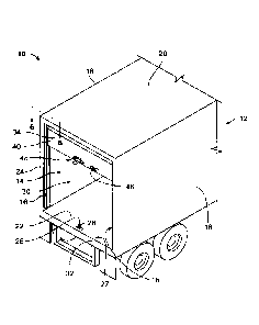
[00241 FIG. 1 is a back, left, top perspective view of a truck trailer,
according to one
embodiment of the invention;
[0025] FIG. 2 is a front, right, perspective view of an overheat door
assembly, disposed
within the truck trailer of FIG. 1;
100261 FIG. 3 is a back, right, top exploded view of a portion of the overhead
door assembly
of FIG. 2;
[0027] FIG. 4 is a back elevational detail view of a door handle assembly and
a valve
assembly disposed within a sill of the truck trailer of FIG. 1;
100281 FIG. 5 is a back elevational detail view of a rotating seal assembly,
disposed within
the truck trailer of FIG. 1;
100291 FIG. 6 is a cross-sectional view of the truck trailer of FIG. 1, taken
along line 6-6; and
100301 FIG. 7 is a cross-sectional view similar to the cross-sectional view of
FIG. 6, but with
a reefer door alternatively installed.
4
Date Regue/Date Received 2022-10-03
DETAILED DESCRIPTION
1003111 Before any embodiments of the invention are explained in detail, it
is to be
understood that the invention is not limited in its application to the details
of constru.ction and the
arrangement of components set forth in the following description or
illustrated in the following
drawings. The invention is capable of other embodiments and of being practiced
or of being
carried out in various ways. Also, it is to be understood that the phraseology
and terminology
used herein is for the purpose of description and should not be regarded as
limiting. The use of
"including," "comprising," or "having" and variations thereof herein is meant
to encompass the
items listed thereafter and equivalents thereof as well as additional items.
Unless specified or
limited otherwise, the terms "mounted," "connected," "supported," and
"coupled" and variations
thereof are used broadly and encompass both direct and indirect mountings,
connections,
supports, and couplings. Further, "connected" and "coupled" are not restricted
to physical or
mechanical connections or couplings_
[0032] The following discussion is presented to enable a person skilled in
the art to make and
use embodiments of the invention. Various modifications to the illustrated
embodiments will be
readily apparent to those skilled in the art, and the generic principles
herein can be applied to
other embodiments and applications without departing from embodiments of the
invention.
Thus, embodiments of the invention are not intended to be limited to
embodiments shown, but
are to be accorded the widest 'scope consistent with the principles and
features disclosed herein.
The following detailed description is to be read with reference to the
figures, in which like
elements in different figures have like reference numerals. The figures, which
are not
necessarily to scale, depict selected embodiments and are not intended to
limit the scope of
embodiments of the invention. Skilled artisans will recognize the examples
provided herein have
many useful alternatives and fall within the scope of embodiments of the
invention.
[0033] In the discussion below, various examples describe an overhead door
rotating seal
assembly for use with various overhead door assemblies (e.g., dry freight door
assemblies,
refrigerated freight door assemblies, etc.) of truck trailers. The overhead
door rotating seal
assembly described is presented as an example only, and the disclosed overhead
door rotating
seal can be used to seal overhead door assemblies with other configurations,
or to seal other
surfaces generally.
Date Regue/Date Received 2022-10-03
100341 As used herein, directional terms including "top," "bottom," "side,"
"horizontal,"
"vertical," and so on are used to indicate directional relationships with
respect to an arbitrary
reference frame (e.g., a reference frame of a particular figure or figures).
These directional terms
are used consistently relative to a particular embodiment. For example, a
"top" feature of an
embodiment is opposite a corresponding "bottom" feature, and a "horizontal"
feature generally
extends perpendicularly to a "vertical" feature. However, unless otherwise
defined or limited,
these directional terms are not intended to indicate an absolute reference
frame for a particular
rotating seal assembly or installation. For example, in some installations or
embodiments, a
"horizontal" feature of a rotating seal assembly, while generally
perpendicular to a "vertical"
feature of the rotating seal assembly, may not necessarily extend in a
strictly horizontal direction
relative to ground.
100351 FIG. 1 illustrates a truck trailer 10 according to one embodiment of
the invention.
The truck trailer 10 includes a housing 12, an overhead door assembly 14, and
two rotating seal
assemblies 16. The housing 12 includes two side walls 18, a top wall 20, a
floor 22, and a rear
wall 24. The rear wall 24 includes a door opening 30 and a sill 32 disposed
adjacent the rear end
27 of the floor 22. The sill 32 includes a latch aperture 26 disposed
proximate a rear end 27 of
the floor 22. The latch aperture 26 defines a substantially rectangular shape
and includes a latch
bar 28. The latch bar 28 extends between two opposing edges of the latch
aperture 26 in a
direction generally perpendicular to the rear wall 24.
100361 As shown in FIGS. 2 and 3, the overhead door assembly 14 includes a
door 34, a
roller track 36, and a lift assist mechanism 38. The door 34 includes several
door panels 40
coupled together by hinges 42 disposed along opposing edges of the door 34.
Each of the hinges
42 further includes a corresponding roller 44 (shown in FIGS. 6 and 7)
configured to roll within
the roller track 36, thereby allowing the door 34 to be moved between an open
position (as
illustrated in FIG. 1) and a closed position (as illustrated in FIG. 2). The
lift assist mechanism 38
is configured to assist in moving the door 34 between the open and closed
positions. As shown
in FIG. 3, the door 34 further includes a handle 46 and a latch assembly 48
configured to latch
the door 34, and thereby lock the door 34 in the closed position.
6
CA 2980863 2017-09-29
100371 As shown in FIG. 4, the latch assembly 48 includes a mounting plate
52, a locking
mechanism 53, and a banana latch 54 including a latch handle 55 rigidly fixed
to a curved arm
56. The banana latch 54 is rotatably coupled to the mounting plate 52 by a pin-
type joint 58.
The curved arm 56 of the banana latch 54 is configured to engage both the
latch bar 28 within
the latch aperture 26 of the floor 22, and an actuation valve assembly 60. The
locking
mechanism 53 is configured to selectively lock the banana latch 54 in
engagement with the latch
bar 28.
100381 The actuation valve assembly 60 is disposed within the sill 32 and
includes a
pneumatic valve 62 and an actuation plate assembly 64. The pneumatic valve 62
is mounted to
an internal surface 66 of the sill 32 using a mounting angle 68 and includes
an inlet line 70
coupled to a pneumatic pressure truck braking system (not shown), an actuation
plunger 72, and
an outlet line splitter 74 connecting to two outlet lines 76. The actuation
plate assembly 64
includes a plunger striker portion 78 and a flexible striker portion 80, both
coupled to a spring-
biased hinge 81. The spring-biased hinge 81 is further coupled to the
pneumatic valve 62. The
actuation plate assembly 64 is configured so that the plunger striker portion
78 and the flexible
striker portion 80 extend in opposite directions. When an end of the flexible
striker portion 80 is
moved in a first direction, the actuation plate assembly 64 rotates about the
spring-biased hinge
81, and the plunger striker portion 78 is moved in a second direction,
substantially opposite the
first direction.
[00391 The spring-biased hinge 81 biases the actuation plate assembly 64
towards an initial
position. In the initial position, the end of the plunger striker portion 78
is disposed proximate a
tip of the actuation plunger 72 and the flexible striker portion 80 extends in
a substantially
vertical direction towards the latch aperture 26 of the floor 22. The flexible
striker portion 80 is
contacted by the curved arm 56 of the banana latch 54 when the door 34 of the
truck trailer 10 is
closed.
[00401 FIGS. 5 and 6 illustrate one of the two rotating seal assemblies 16,
according to one
embodiment of the invention. The two rotating seal assemblies 16 are similar,
but generally
form mirror images of each other. The two rotating seal assemblies 16 are
disposed within the
truck trailer 10, at rear corners of the truck trailer 10 spanning from the
floor 22 to the top wall
7
CA 2980863 2017-09-29
20. As illustrated, the rotating seal assembly 16 includes a pneumatic
actuation mechanism 82, a
center shaft 84, and a rotary seal 86. The pneumatic actuation mechanism 82
includes an inlet
line 88 connected to one of the two outlet lines 76 of the actuation valve
assembly 60, a cylinder
90, and a piston rod 92. The center shaft 84 extends from within the sill 32,
through an upper
interior surface 94 of the sill 32, through the interior portion of the truck
trailer 10, and through
the top wall 20 of the truck trailer 10. Additionally, the center shaft 84
includes a top bearing 96,
coupled to the top wall 20 of the truck trailer 10, a bottom bearing 98,
coupled to the upper
interior surface 94 of the sill 32, and an arm 100 extending radially outward
from the center shaft
84 and rigidly fixed thereto. The arm 100 is disposed within the sill 32 and
is coupled to an end
of the piston rod 92 of the pneumatic actuation mechanism 82. The rotary seal
86 is rigidly fixed
to the center shaft 84, so that the rotary seal 86 is rotatable with the
center shaft 84. As shown in
FIG. 6, the rotary seal 86 includes a central cylinder portion 102, a flexible
wall portion 104, and
a flexible door portion 106.
100411 The rotary seal 86 is actuatable between a non-sealing position (as
shown by solid
lines in FIG. 6) and a sealing position (as shown by dashed lines in FIG. 6).
In the non-sealing
position, the flexible wall portion 104 is disposed proximate the rear wall
24, with a slight gap
therebetween. Also in the non-sealing position, the flexible door portion 106
is disposed
between the rear wall 24 and the door 34, generally adjacent the rear wall 24.
In the sealing
position, the center shaft 84, and therefore the rotary seal 86, is rotated so
that the flexible wall
portion 104 of the rotary seal 86 is compressed against the rear wall 24 of
the truck trailer 10 and
the flexible door portion 106 of the rotary seal 86 is compressed against the
door 34, thereby
providing a seal between the door 34 and the rear wall 24.
[00421 FIG. 7 illustrates a rotating seal assembly 16' installed into a
refrigerated truck trailer
10', according to one embodiment of the invention. The rotating seal assembly
16' and the
refrigerated truck trailer 10' are generally similar to the rotating seal
assembly 16 and the truck
trailer 10 depicted in FIGS. 1-6, with like numbers labeled similarly in the
prime series (e.g.,
flexible wall portion 104 and flexible wall portion 104', roller track 36 and
roller track 36', etc.).
The door 34' of the refrigerated truck trailer 10' is considerably thicker
than the door 34 of the
truck trailer 10. Even so, the configuration of the rotating seal assembly 16'
is still able to
provide an actuatable seal between the door 34' and the rear wall 24'.
8
CA 2980863 2017-09-29
100431 Now that the structure of the rotating seal assembly 16 has been
described above, a
method of producing the rotating seal assembly 16 will be described below. It
will be
understood that the method of producing the rotating seal assembly 16 is given
only as an
example. The rotating seal assembly 16 can be produced according to a variety
of methods, and
the following example is not meant to be limiting.
100441 The rotary seal 86 of the rotating seal assembly 16 can be
manufactured through a
dual extrusion process. The dual extrusion process can allow for the central
cylinder portion 102
to be made of a hard, rigid plastic material, while both the flexible wall
portion 104 and the
flexible door portion 106 are made of a soft, flexible plastic material.
100451 Alternatively, the rotary seal 86 of the rotating seal assembly 16
can be manufactured
with a central cylinder portion 102 that is produced separately from the
flexible wall portion 104
and the flexible door portion 106. In these instances, the flexible wall
portion 104 and the
flexible door portion 106 can be rigidly fixed to the central cylinder portion
102 using fasteners,
adhesive, or other suitable coupling methods. Similarly, in some embodiments,
the rotary seal
86 may not include the central cylinder portion 102. In these instances, the
flexible door portion
106 and the flexible wall portion 104 can be directly coupled to the center
shaft 84 of the rotating
seal assembly 16.
100461 Now that the structure and method of manufacturing of the rotating
seal assembly 16
have been described above, an exemplary method of use will be described below.
Again, it will
be understood that the method of use described below is given as an example,
and is not meant to
be limiting.
100471 During use, the rotating seal assembly 16 is configured to be in the
non-sealing
position while the door 34 is open. With the rotating seal assembly 16 in the
non-sealing
position, the door 34 is movable between the open and closed positions,
thereby allowing an
operator to enter the truck trailer 10 to load and unload various freight into
and out of the truck
trailer 10.
100481 Once the operator exits the truck trailer 10, the operator can close
the door 34. The
operator can then use the latch assembly 48 to lock the door 34 in the closed
position by rotating
9
CA 2980863 2017-09-29
the latch handle 55 of the banana latch 54 clockwise to a locked position. In
the locked position,
the curved arm 56 of the banana latch 54 extends through the latch aperture 26
in the floor 22 of
the truck trailer 10, into the interior portion of the sill 32, with the
curved arm 56 disposed below
the latch bar 28. In this configuration, the curved arm 56 engages the latch
bar 28, preventing
the door 34 from being raised, and thereby locking the door 34 in the closed
position.
100491 Additionally, when the banana latch 54 is rotated into the locked
position, a tip of the
curved arm 56 contacts the flexible striker portion 80 of the actuation plate
assembly 64 and
moves the flexible striker portion 80 in the first direction. When the
flexible striker portion 80 is
moved in the first direction, the actuation plate assembly 64 rotates about
the spring-biased hinge
81, and the plunger striker portion 78 is moved in the second direction and
compresses the
actuation plunger 72.
100501 When the plunger striker portion 78 compresses the actuation plunger
72, the
actuation plunger 72 actuates the actuation valve assembly 60, which is
configured to allow
pressurized air to travel from the pneumatic brake pressure system of the
truck trailer 10, through
the inlet line 70, through the pneumatic valve 62, and into the outlet line
splitter 74. From the
outlet line splitter 74, the pressurized air travels through the two outlet
lines 76 to each of the two
rotating seal assemblies 16.
100511 As the pressurized air travels from the outlet lines 76 of the
actuation valve assembly
60, it reaches the inlet lines 88 of each of the rotating seal assemblies 16.
From the inlet lines 88,
the pressurized air pressurizes the cylinder 90 of the pneumatic actuation
mechanism 82. This
pressurization forces the piston rod 92 to move out of the pneumatic actuation
mechanism 82.
As the piston rod 92 is moved out of the pneumatic actuation mechanism 82, the
pneumatic
actuation mechanism 82 is configured to move the arm 100 of the rotating seal
assembly 16.
Since the arm 100 is rigidly fixed to the center shaft 84, as the arm 100 is
moved, the center shaft
84 rotates and moves the rotary seal 86 from the non-sealing position into the
sealing position.
100521 When the operator is ready to open the truck trailer 10, the
operator can first unlock
the door 34 by rotating the latch handle 55 of the banana latch 54 counter-
clockwise to an
unlocked position. In the unlocked position, the curved arm 56 of the banana
latch 54 is rotated
CA 2980863 2017-09-29
so that no portion of the curved arm 56 is directly below the latch bar 28. In
this configuration,
the latch bar 28 does not prevent the door 34 from being raised.
[0053] When the banana latch 54 is rotated into the unlocked position, the
tip of the curved
arm 56 comes out of contact with the flexible striker portion 80 of the
actuation plate assembly
64. Since the spring-biased hinge 81 biases the actuation plate assembly 64
towards the initial
position, the actuation plate assembly 64 then returns to its initial
position, decompressing the
actuation plunger 72.
[0054] When the actuation plunger 72 decompresses, the pneumatic valve 62
is configured to
relieve the pressure accumulated in the two outlet lines 76, which in turn
relieves the pressure in
each of the pneumatic actuation mechanisms 82 of each of the two rotating seal
assemblies 16.
As the pressure is relieved in each of the pneumatic actuation mechanisms 82,
the pressure in
each of the cylinders 90 drops, allowing the piston rod 92 to retract into the
pneumatic actuation
mechanism 82. Accordingly, as the pneumatic actuation mechanism 82 is
retracted, the arm 100
of the rotating seal assembly 16 is moved, so that the center shaft 84 rotates
the rotary seal 86
from the sealing position into the non-sealing position.
[0055] In some embodiments, the rotating seal assemblies 16 may be biased
towards the non-
sealing position. This biasing may be achieved with torsional springs (not
shown) applied to the
center shafts 84, with linear springs (not shown) attached to the arms 100, or
by using other
suitable biasing means.
[0056] It will be understood that the embodiments discussed above are
presented as
examples only, and that other embodiments are possible. For example, in the
rotating seal
assemblies 16, the flexible door portion 106 contacts a rear facing surface of
the door 34. In
other embodiments, a rotating seal assembly 16 may be configured so that the
flexible door
portion 106 alternatively contacts a side edge surface of the door 34.
100571 Thus, embodiments of the invention provide a seal assembly for
providing an
actuatable rotational seal between a door and a rear wall of a truck trailer.
The improved seal
assembly can provide improved ease of use as compared to conventional truck
trailer sealing
methods, and can be implemented on both dry freight and refrigerated freight
truck trailers.
11
CA 2980863 2017-09-29
Further, some embodiments of the improved seal assembly can be manufactured
from a dual
extrusion process, thereby reducing the need for secondary assembly processes.
[0058]
The previous description of the disclosed embodiments is provided to enable
any
person skilled in the art to make or use the invention. Various modifications
to these
embodiments will be readily apparent to those skilled in the art, and the
generic principles
defined herein may be applied to other embodiments without departing from the
spirit or scope
of the invention. Thus, the invention is not intended to be limited to the
embodiments shown
herein but is to be accorded the widest scope consistent with the principles
and novel features
disclosed herein.
12
CA 2980863 2017-09-29