Note: Descriptions are shown in the official language in which they were submitted.
CA 02980889 2017-09-25
NSSMC Ref. FP152728
Our Ref. 102-237-P1
STAINLESS STEEL AND STAINLESS STEEL PRODUCT FOR OIL WELL
TECHNICAL FIELD
[0001] The present invention relates to a stainless steel, and more
particularly to a stainless steel product for an oil well.
BACKGROUND ART
[0002] Conventionally, martensitic stainless steel has been widely used in
oil-well environments. A conventional oil-well environment contains carbon
dioxide gas (CO2) and/or chloride ions (CI-). A martensitic stainless steel
containing about 13 mass% Cr (hereinafter referred to as 13 % Cr steel) has
good corrosion resistance in such a conventional oil-well environment.
[0003] In recent years, higher oil prices have prompted development of
deep-sea oil wells. Deep-sea oil wells are located at large depths. In
addition, deep-sea oil wells have high corrosivity and high temperatures.
More specifically, a deep-sea oil well contains high-temperature corrosive
gases. Such corrosive gases contain CO2 and/or Cl-, and may contain
hydrogen sulfide gas. A corrosion reaction at a high temperature is severer
than a corrosion reaction at room temperature. In view of this, an oil-well
steel for use in a deep-sea oil well is required to have a strength and
corrosion resistance higher than those of a 13 % Cr steel.
[0004] A duplex stainless steel has a higher Cr content than a 13 % Cr steel.
Thus, a duplex stainless steel has a higher corrosion resistance than a 13 %
Cr steel. A duplex stainless steel may be, for example, a 22 % Cr steel
containing 22 % Cr, or a 25 % Cr steel containing 25 % Cr. However, a
duplex stainless steel is expensive as it contains a larger amount of alloy
elements. Thus, there is a demand for a stainless steel that has a higher
corrosion resistance than a 13 % Cr steel and is less expensive than a duplex
stainless steel.
[0005] To address this demand, a stainless steel containing 15.5 to 18 % Cr
and having high corrosion resistance in high-temperature oil-well
environments has been proposed. JP 2005-336595 A (Patent Document 1)
proposes a stainless steel pipe having high strength and having carbon
dioxide gas corrosion resistance in high-temperature environments at 230 C.
The chemical composition of this steel pipe includes 15.5 to 18 % Cr, 1.5 to
% Ni, and 1 to 3.5 % Mo, satisfies Cr+0.65Ni+0.6Mo+0.55Cu-20C>19.5 and
1
CA 02980889 2017-09-25
NSSMC Ref. FP152728
Our Ref. 102-237-P1
satisfies Cr+Mo+0.3Si-43.5C-0.4Mn¨Ni-0.3Cu-9N>11.5. The metal
structure of this steel pipe contains 10 to CO % ferrite and 30 % or less
austenite, the balance being martensite.
[0006] WO 2010/050519 A (Patent Document 2) proposes a stainless steel
pipe having corrosion resistance in high-temperature carbon dioxide gas
environments at 200 C and having high sulfide stress corrosion cracking
resistance even when the environment temperature in the oil well or gas well
falls after removal of oil or gas is temporarily stopped. The chemical
composition of this steel pipe includes more than 16 % to 18 % Cr, more than
2 % to 3 % Mo, 1 to 3.5 % Cu and 3 to less than 5 % Ni, and satisfies
[Mn]x([N]-0.0045)<0.001. The metal structure of this steel pipe contains,
by volume ratio, 10 to 40 % ferrite and 10 % or less retained austenite, the
balance being martensite.
[0007] WO 2010/134498 (Patent Document 3) proposes a high-strength
stainless steel having good corrosion resistance in high-temperature
environments and having good SSC resistance at room temperature. The
chemical composition of this steel includes more than 16 % to 18 % Cr, 1.6 to
4.0 % Mo, 1.5 to 3.0 Cu and more than 4.0 to 5.6 % Ni, satisfies
Cr+Cu+Ni+Mo>25.5, and satisfies
¨8<30(C+N)+0.5Mn+Ni+Cu/2+8.2-1.1(Cr+Mo) <-4. The metal structure of
this steel contains martensite, 10 to 40 % ferrite, and retained austenite,
where the ferrite distribution ratio is higher than 85 %.
[0008] In high Cr stainless steels containing 15.5 to 18 % Cr disclosed in
these documents, the low-temperature toughness may often be insufficient.
JP 2010-209402 A (Patent Document 4) proposes a high-strength stainless
steel pipe for an oil well with good low-temperature toughness. This steel
pipe contains 15.5 to 17.5 % Cr, where the distance between any two points
in the largest crystal grain in the microstructure is not higher than 200 pm
(in other words, the crystal grain diameter is not larger than 200 pm).
Further, WO 2013/179667 (Patent Document 5) describes that a steel has
both good corrosion resistance and good low-temperature toughness if it has
a microstructure in which the GSI value, which is defined as the number of
ferrite-martensite grain boundaries present per unit length along a line
segment extending in the wall-thickness direction.
DISCLOSURE OF THE INVENTION
2
CA 02980889 2017-09-25
NSSMC Ref. FP152728
Our Ref. 102-237-P1
[0009] However, when toughness is evaluated in connection with fracture
appearance transition temperature, even these techniques may not achieve a
sufficient low-temperature toughness. Particularly, this problem is
significant when the wall thickness is large.
[0010] An object of the present invention is to provide a stainless steel and
a
stainless steel product for an oil well having high strength and exhibiting
good stress corrosion cracking resistance (SCC resistance) at high
temperatures and good sulfide stress corrosion cracking resistance (SSC
resistance) at room temperature as well as good low-temperature toughness.
[0011] A stainless steel according to an embodiment of the present invention
has a chemical composition including, in mass%; C: 0.001 to 0.06 %; Si: 0.05
to 0.5 %; Mn: 0.01 to 2.0 %; P: up to 0.03 %; S: less than 0.005 %; Cr: 15.5
to
18.0 %; Ni: 2.5 to 6.0 %; V: 0.005 to 0.25 %; Al: up to 0.05 %; N: up to 0.06
%;
0: up to 0.01 %; Cu: 0 to 3.5 %; Co: 0 to 1.5 %; Nb: 0 to 0.25 %; Ti: 0 to
0.25 %;
Zr: 0 to 0.25 %; Ta: 0 to 0.25 %; B: 0 to 0.005 %; Ca: 0 to 0.01 %; Mg: 0 to
0.01 %; and REM: 0 to 0.05 %, further including one or two selected from the
group consisting of: Mo: 0 to 3.5 %; and W: 0 to 3.5 % in an amount that
satisfies Equation (1), the balance being Fe and impurities. The stainless
steel has a matrix structure having, by volume ratio, 40 to 80 % tempered
martensite, 10 to 50 % ferrite and 1 to 15 % austenite. When a
microstructure image with dimensions of 1 mm 1 mm obtained by
photographing the matrix structure at a magnification of 100 times is
positioned in an x-y coordinate system with an x-axis formed by a
wall-thickness direction and a y-axis formed by a length direction and each
of 1024x1024 pixels is represented by a gray scale level, 6 defined by
Equation (2) is not smaller than 1.55:
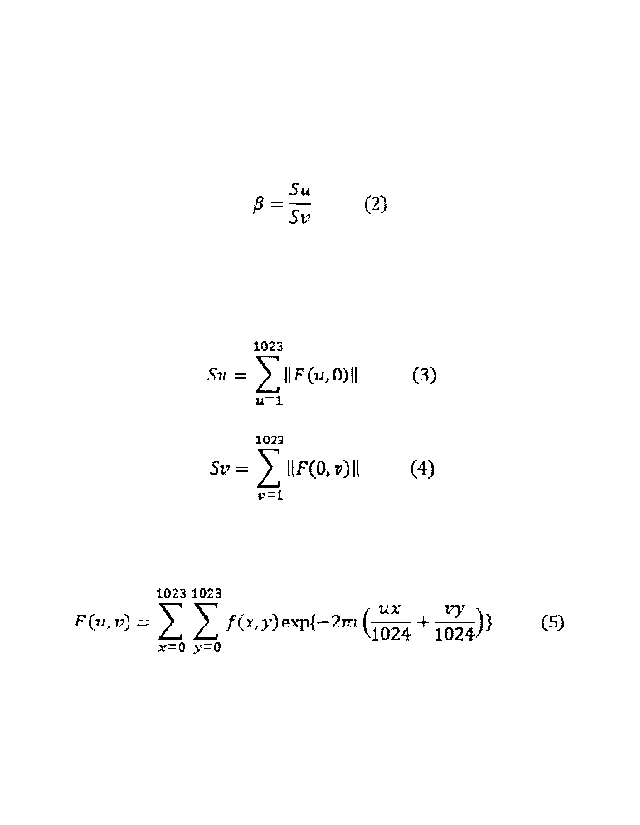
1.0<Mo+0.5W<3.5 (1).
[0012] Here, Mo and W are the Mo and W contents in mass%.
[Formula 1]
Su
= ¨Sv (2)
[0013] In Equation (2), Su is defined by Equation (3), and Sv is defined by
Equation (4):
[Formula 2]
3
1023
SU = IIF(UMII (3)
u=1.
1filg
SV = IIF(0, V) II (4)
v=t
[0014] In Equations (3) and (4), F(u,v) is defined by Equation (5):
[Formula 3]
1023 1023
UX24 vy
F eu vi; = f (x y) expf ¨2rt-i 10 + 4)} (S)
102
x=0 y=0
NW In Equation (5), f(x,y) represents the gray level of the pixel at
coordinates (x,y).
[0016] The stainless steel and stainless steel product for an oil well
according to the present invention have high strength, good SCC resistance
at high temperatures and good SSC resistance at room temperature, and
good low-temperature toughness.
BRIEF DESCRIPTION OF THE DRAWINGS
[0017] [FIG. 1] FIG. 1 is a microstructure image showing an example of a
microstructure of a stainless steel in an embodiment of the present
invention.
[FIG. 2] FIG. 2 is a logarithmic frequency spectrogram obtained by
performing two-dimensional discrete Fourier transform on the
microstructure image of FIG. 1.
[FIG. 3] FIG. 3 is a picture showing an example of a microstructure of
a stainless steel of a comparative example.
[FIG. 4] FIG. 4 is a logarithmic frequency spectrogram obtained by
performing two-dimensional discrete Fourier transform on the
microstructure image of FIG. 3.
[FIG. 51 FIG. 5 is a microstructure image showing an example of a
microstructure of a stainless steel in an embodiment of the present
invention.
[FIG. 6] FIG. 6 is a logarithmic frequency spectrogram obtained by
performing two-dimensional discrete Fourier transform on the
microstructure image of FIG. 5.
4
CA 2980889 2018-12-03
CA 02980889 2017-09-25
NSSMC Ref. FP152728
Our Ref. 102-237-P1
[FIG. 71 FIG. 7 is a picture showing an example of a microstructure of
a stainless steel of a comparative example.
[FIG. 8] FIG. 8 is a logarithmic frequency spectrogram obtained by
performing two-dimensional discrete Fourier transform on the
microstructure image of FIG. 7.
[FIG. 9] FIG. 9 is a graph illustrating the relationship between 13 and
the transition temperature for ductile brittleness.
EMBODIMENTS FOR CARRYING OUT THE INVENTION
[0018] To solve the above problems, the present inventors investigated
conditions relating to low-temperature toughness. The present inventors
arrived at the following findings.
[0019] The matrix structure of a stainless steel includes ferrite and
tempered martensite and austenite (hereinafter referred to as substantially
martensitic phase). If, in the matrix structure, the ferritic phase and the
substantially martensitic phase extend in the rolling direction (i.e. length
direction) and are arranged in a layered manner, the stainless steel has good
low-temperature toughness. On the other hand, if, in the matrix structure,
the ferritic phase is randomly distributed in a grid manner, the stainless
steel has low low-temperature toughness. If the stainless steel is a steel
plate, rolling direction is defined by the central axis of the steel plate
extended by the rolling. If the stainless steel is a steel pipe, rolling
direction is defined by the central axis of the steel pipe.
[0020] The present inventors found that the degree of layeredness of the
microstructure which represents the ferritic phase and substantially
martensitic phase in the stainless steel extending long in the length
direction can be evaluated and quantized in terms of both the wall-thickness
direction and length direction by performing two-dimensional discrete
Fourier transform on a microstructure image. This point will be discussed
in further detail below.
[0021] A microstructure image with dimensions of 1 mm x 1 mm at an
observation magnification of 100 times is taken of a cut surface
perpendicular to an arbitrary plate-width direction of a stainless steel by
picturing it by optical microscopy and rendering it using gray scale (256
levels). One example of a microstructure image is shown in FIG. 1. In FIG.
1, the microstructure image is positioned in an x-y coordinate system. The
CA 02980889 2017-09-25
NSSMC Ref. FP152728
Our Ref. 102-237-P1
y-axis in FIG. 1 represents the length direction while the x-axis represents
the wall-thickness direction, perpendicular to the length direction. In FIG.
1, a gray portion represents a substantially martensitic phase, and a white
portion located between grains of the substantially martensitic phase
represents ferrite. The microstructure image has M=1024 pixels in a series
in the x-axis direction and N=1024 pixels in a series in the y-axis direction.
That is, the microstructure image has MxI\1,---1024x1024 pixels.
100221 From the microstructure image, two-dimensional data f(x,y) is
obtained for each pixel (x,y) (x=0 to M-1, y=0 to N-1). f(x,y) represents a
level in gray scale for the pixel at coordinates (x,y). A two-dimensional
discrete Fourier transform (2D DFT) defined by Equation (5) is performed on
the obtained two-dimensional data. M-1=1023, N-1=1023.
[Formula 4]
CM 1 CPR
VY )1
F(u,v) => f(xy)exp{-2711 (111,X024 4_ 1024)j (5)
x0 y0
[00231 Here, F(u,v) is the two-dimensional frequency spectrum of the
two-dimensional data f(x,y) after the two-dimensional discrete Fourier
transform. The frequency spectrum F(u,v) is typically a complex number,
and contains information about the periodicity and regularity of the
two-dimensional data f(x,y). In other words, the frequency spectrum F(u,v)
contains information about the periodicity and regularity of the structure of
the ferritic phase and substantially martensitic phase in a microstructure
image such as that shown in FIG. 1.
100241 FIG. 2 is a logarithmic frequency spectrogram from the
microstructure image of FIG. 1. The horizontal axis of FIG. 2 forms the
v-axis, while the vertical axis forms the u-axis. The frequency spectrogram
of FIG. 2 is a black/white gray-level image (i.e. gray-scale image), where the
maximum value of frequency spectrum is white and the minimum value is
black. A portion with higher frequency spectrum values (i.e. white portion
in FIG. 2) may be in a shape extending along the u-axis, as in FIG. 2, without
clear borders.
[0025] In connection with the frequency spectrum F(u,v) of the frequency
spectrogram, the total Su of absolute spectral values along the u-axis is
defined by Equation (3). In connection with the frequency spectrum F(u,v),
the total Sv of absolute spectral values along the v-axis is defined by
6
CA 02980889 2017-09-25
NSSMC Ref. FP152728
Our Ref. 102-237-P1
Equation (4). Further, the ratio of Su to Sy is B defined by Equation (2).
Su and Sy do not include the spectral intensity at coordinates (0,0) in the
(u,v) space.
[Formula 5]
1023
II F .1 (3)
u=i
iron
= (4)
v=1.
su
= S¨v
[0026] Further, in a similar manner, the microstructure images of stainless
steels shown in FIGS. 3, 5 and 7 are obtained. Further, from the
microstructure images shown in FIGS. 3, 5 and 7, logarithmic frequency
spectrograms are obtained. FIG. 4 is a logarithmic frequency spectrogram
from the microstructure image of FIG. 3, FIG. 6 is a logarithmic frequency
spectrogram from the microstructure image of FIG. 5, and FIG. 8 is a
logarithmic frequency spectrogram from the microstructure image of FIG. 7.
In the following description, the microstructure of FIG. 1 will be referred to
as structure 1, the microstructure of FIG. 3 will be referred to as structure
2,
the microstructure of FIG. 5 will be referred to as structure 3, and the
microstructure of FIG. 7 will be referred to as structure 4.
[0027[ A comparison between the image of structure 1 (FIG. 1) and the
image of structure 2 (FIG. 3) shows that structure 1 has a ferritic phase and
substantially martensitic phase extending along the rolling direction (i.e.
length direction) compared with structure 2. Further, in structure 1, the
lamination period of the ferritic phase and substantially martensitic phase
(i.e. period in which they are arranged in the wall-thickness direction) is
shorter than in structure 2, and these phases are more regular. A
comparison between the image of structure 1 and the image of structure 3
(FIG. 5) shows that both structures 1 and 3 have each phase extending along
the length direction. Further, similar to structure 1, structure 3 has a
shorter lamination period and more regular phases. A comparison between
the image of structure 3 and the image of structure 4 (FIG. 7) shows that
structure 3 has each phase extending along the length direction compared
7
CA 02980889 2017-09-25
NSSMC Ref. FP152728
Our Ref. 102-237-P1
with structure 4. Further, structure 3 has a shorter lamination period and
more regular phases than structure 4.
[0028] Further, in each of the logarithmic frequency spectrograms of
structures 1 to 4, a white portion extends along the u-axis. However, in
structures 1 and 3, the width of the white portion, measured in the v-axis
direction, is smaller than in structures 2 and 4. The value of 6 is 2.024 in
structure 1, 1.458 in structure 2, 2.183 in structure 3, and L395 in structure
4. In short, as the
value of 8 decreases, the white portion becomes shorter
as measured in the u-axis direction and broader as measured in the v-axis
direction.
[0029] Further, the transition temperature for ductile brittleness is ¨82 C
in structure 1, ¨12 C in structure 2, ¨109 C in structure 3, and ¨19 C in
structure 4. The values of transition temperature results from conditions
similar to those for the Examples described further below. FIG. 9 is a graph
illustrating the relationship between 13 and the transition temperature ( C).
FIG. 9 was created by the following procedure: A plurality of stainless steels
with chemical compositions within the ranges of the present embodiment
described below and with different values of 6 were produced. For each
stainless steel, the low-temperature toughness evaluation test described
below was conducted to obtain a transition temperature value, and FIG. 9
was created based on these values. The straight line in FIG. 9 was obtained
by the method of least squares from all the plot points in FIG. 9, where R2 is
a correlation function.
[0030] Thus, it was found that the larger the value of 6, the better the
low-temperature toughness tends to be. Consequently, B can be regarded as
indicative of the degree of layeredness.
[0031] 13 may be increased by hot rolling the steel material with a large
fraction of austenite at the temperature for hot rolling and with a high
reduction of sectional area. The fraction of austenite at the temperature for
hot rolling may be increased by adjusting the chemical composition of the
steel material or lowering the temperature of the hot rolling. However, if
the temperature for hot rolling is too low, hot workability decreases, which
may cause flaws on the surface of the steel material. Also, there is a limit
to
the increase of the reduction of sectional area.
[0032] The chemical composition may be adjusted to increase the fraction of
austenite at the temperature for hot rolling by increasing the contents of
8
austenite-forming elements such as C, Ni, Cu and Co or reducing the
contents of ferrite-forming elements such as Si, Cr, V, Mo and W. It is
particularly effective to increase the Ni content. This makes 6 equal to or
greater than 1.55 while the rolling temperature and reduction of sectional
area are in a practical range. On the other hand, if the chemical
composition is adjusted to increase the fraction of austenite at the
temperature for hot rolling, the fraction of austenite at room temperature,
i.e.
the amount of retained austenite tends to be large. This makes it difficult
to provide a required strength.
[0033] After further research, the present inventors found that it is
effective
if V is contained in the steel material. As discussed above, V is a
ferrite-forming element, and is thus disadvantageous when the fraction of
austenite at the temperature for hot rolling is to be increased. On the other
hand, V increases temper softening resistance to improve the strength of the
steel. An appropriate V content makes it possible to make 6 equal to or
greater than 1.55 and, at the same time, provide a required strength.
[0034] The present inventors made the present invention based on the
above-described findings. First, a summary of an embodiment of the
present invention will be provided.
[0035] A stainless steel according to an embodiment of the present invention
has a chemical composition including, in mass%: C: 0.001 to 0.06 %; Si: 0.05
to 0.5 %; Mn: 0.01 to 2.0 %; P: up to 0.03 %; S: less than 0.005 %; Cr: 15.5
to
18.0 %; Ni: 2.5 to 6.0 %; V: 0.005 to 0.25 %; Al: up to 0.05 %; N: up to 0.06
%;
0: up to 0.01 %; Cu: 0 to 3.5 %; Co: 0 to 1.5 %; Nb: 0 to 0.25 %; Ti: 0 to
0.25 %;
Zr: 0 to 0.25 %; Ta: 0 to 0.25 %; B: 0 to 0.005 %; Ca: 0 to 0.01 %; Mg: 0 to
0.01 %; and REM: 0 to 0.05 %. It further includes one or two selected from
the group consisting of: Mo: 0 to 3.5 %; and W: 0 to 3.5 % in an amount that
satisfies Equation (1). The balance is Fe and impurities. The stainless
steel has a matrix structure having, by volume ratio, 40 to 80 % tempered
martensite, 10 to 50 % ferrite and 1 to 15 % austenite. When a
microstructure image with dimensions of 1 mm x 1 mm obtained by
photographing the matrix structure at a magnification of 100 times is
positioned in an x-y coordinate system with an x-axis extending in a
wall-thickness direction and a y-axis extending in a length direction and
each of 1024x1024 pixels is represented by a gray scale level, 6 defined by
Equation (2) is not smaller than 1.55:
9
CA 2980889 2019-06-06
CA 02980889 2017-09-25
NSSMC Ref. FP152728
Our Ref. 102-237-P1
1.0<Mo+0.5W<3.5 (1).
[0036] Here, Mo and W are the Mo and W contents in mass%.
[Formula 61
--= ¨ (2)
Sv
[0037] in Equation (2), Su is defined by Equation (3), and Sv is defined by
Equation (4):
[Formula 71
1023
Su = 111F (u, 0)11 (3)
u=3.
12
Sv = DM, 7) II (4)
[0038] In Equations (3) and (4), F(u,v) is defined by Equation (5):
[Formula 81
1023 1023
UX Vy
F (u, = f (x y) exp{-2zi ¨ (5)
1024 1024
x=o y=0
[0039] In Equation (5), f(x,y) represents the gray level of the pixel at
coordinates (x,y).
100401 In this stainless steel, 8 is not lower than 1.55 such that the
transition temperature for ductile brittleness is not higher than ¨30 C. As
a result, this stainless steel has good low-temperature toughness. Further,
this stainless steel has high strength and good SCC resistance at high
temperatures and good SSC resistance at room temperature.
[0041] The chemical composition of the stainless steel in an embodiment of
the present invention may include one or two selected from the group
consisting of, in mass%; Cu: 0.2 to 3.5 %; and Co: 0.05 to 1.5 %.
[0042] The chemical composition of the stainless steel in an embodiment of
the present invention may include one or more selected from the group
consisting of, in mass%: Nb: 0.01 to 0.25 %; Ti: 0.01 to 0.25 %; Zr: 0.01 to
0.25 %; and Ta: 0.01 to 0.25 %.
[0043] The chemical composition of the stainless steel in an embodiment of
the present invention may include one or more selected from the group
consisting of, in mass%: B: 0.0003 to 0.005 %; Ca: 0.0005 to 0.01 %; Mg:
CA 02980889 2017-09-25
NSSMC Ref. FP152728
Our Ref. 102-237-P1
0.0005 to 0.01 %; and REM: 0.0005 to 0.05 %.
[0044] Preferably, the stainless steel in an embodiment of the present
invention is used as a steel product for an oil well.
[0045] [Chemical Composition]
The stainless steel in an embodiment of the present invention has the
chemical composition described below. In the description below, "%" for an
element means mass percentage.
[0046] C: 0.001 to 0.06 %
Carbon (C) increases the strength of steel. However, if the C content
is too high, the hardness after tempering is too high, decreasing SSC
resistance. Further, in the chemical composition of the present embodiment,
the Ms point falls as the C content increases. As such, as the C content
increases, austenite tends to increase and yield strength tends to decrease.
In view of this, the C content should be not higher than 0.06 %. The C
content is preferably not higher than 0.05 %, and more preferably not higher
than 0.03 %. Further, when the costs associated with the decarburization
step in the steel-making process are considered, the C content should be not
lower than 0.001 %. The C content is preferably not lower than 0.003 %,
and more preferably not lower than 0.005 %.
[0047] Si: 0.05 to 0.5 %
Silicon (Si) deoxidizes steel. However, if the Si content is too high,
the toughness and hot workability of the steel decrease. Further, if the Si
content is too high, the amount of ferrite produced increases and yield
strength tends to decrease. Further, it becomes difficult to increase 6. In
view of this, the Si content should be in the range of 0.05 to 0.5 %. The Si
content is preferably lower than 0.5 %, and more preferably not higher than
0.4 %. The Si content is preferably not lower than 0.06 %, and more
preferably not lower than 0.07 %.
[0048] Mn: 0.01 to 2.0 %
Manganese (Mn) deoxidizes and desulfurizes steel, increasing hot
workability. These effects are not sufficiently present if the Mn content is
too low. On the other hand, if the Mn content is too high, excess austenite
tends to remain during quenching, making it difficult to maintain the
strength of the steel. In view of this, the Mn content should be in the range
of 0.01 to 2.0 %. The Mn content is preferably not higher than 1.0 %, and
more preferably not higher than 0.6 %. The Mn content is preferably not
11
CA 02980889 2017-09-25
NSSMC Ref. FP152728
Our Ref. 102-237-P1
lower than 0.02 %, and more preferably not lower than 0.04 %.
[0049] P: up to 0.03 %
Phosphorus (P) is an impurity. P decreases the SSC resistance of
steel. Thus, the lower the P content, the better. The P content should be
not higher than 0.03 %. The P content is preferably not higher than 0.028 %,
and more preferably not higher than 0.025 %. Although it is preferable to
reduce the P content to the lowest possible level, reducing it excessively
leads
to increased steel-making costs. Thus, the P content is preferably not lower
than 0.0005 %, and more preferably not lower than 0.0008 %.
[0050] S: lower than 0.005 %
Sulfur (S) is an impurity. S decreases the hot workability of steel.
Thus, the lower the S content, the better. The S content should be lower
than 0.005 %. The S content is preferably not higher than 0.003 %, and
more preferably not higher than 0.0015 %. Although it is preferable to
reduce the S content to the lowest possible level, reducing it excessively
leads
to increased steel-making costs. Thus, the S content is preferably not lower
than 0.0001 %, and more preferably not lower than 0.0003 %.
[0051] Cr: 15.5 to 18.0 %
Chromium (Cr) increases the corrosion resistance of steel. More
specifically, Cr decreases the corrosion rate, thereby increasing the SCC
resistance of the steel. These effects are not sufficiently present if the Cr
content is too low. On the other hand, if the Cr content is too high, the
volume ratio of ferrite in the steel increases, decreasing the strength of the
steel. Further, it becomes difficult to increase B. In view of this, the Cr
content should be in the range of 15.5 to 18.0 %. The Cr content is
preferably not higher than 17.8 %, and more preferably not higher than
17.5 %. The Cr content is preferably not lower than 16.0 %, and more
preferably not lower than 16.3 %.
[0052] Ni: 2.5 to 6.0 %
Nickel (Ni) increases the toughness of steel. Further, Ni increases
the strength of the steel. Ni increases the fraction of austenite at
temperatures for hot working and contributes to increasing B. These effects
are not sufficiently present if the Ni content is too low. On the other hand,
if
the Ni content is too high, a large amount of retained austenite tends to be
produced, decreasing the strength of the steel. In view of this, the Ni
content should be in the range of 2.5 to 6.0 %. The Ni content is preferably
12
CA 02980889 2017-09-25
NSSMC Ref. FP152728
Our Ref. 102-237-P1
lower than 6.0 %, and more preferably not higher than 5.9 %. The Ni
content is preferably not lower than 3.0 %, and more preferably not lower
than 3.5 %.
[0053] V: 0.005 to 0.25 %
Vanadium (V) increases the strength of steel. If the V content is
lower than 0.005 %, a required strength cannot be provided. However, if the
V content is too high, toughness decreases. Further, it becomes difficult to
increase 8. In view of this, the V content should be in the range of 0.005 to
0.25 %. The V content is preferably not higher than 0.20 %, and more
preferably not higher than 0.15 %. The V content is preferably not lower
than 0.008 %, and more preferably not lower than 0.01 %.
[0054] Al: up to 0.05 %
Aluminum (Al) deoxidizes steel. However, if the Al content is too
high, inclusions in the steel increase, decreasing the toughness of the steel.
In view of this, the upper limit should be 0.05 %. The Al content is
preferably not higher than 0.048 %, and more preferably not higher than
0.045 %. The Al content is preferably not lower than 0.0005 %, and more
preferably not lower than 0.001 %.
[0055] N: up to 0.06 %
Nitrogen (N) increases the strength of steel. However, if the N
content is too high, excess austenite is produced, increasing inclusions in
the
steel. As a result, the toughness of the steel decreases. In view of this, the
N content should be not higher than 0.06 %. The N content is preferably
not higher than 0.05 %, and more preferably not higher than 0.03 %.
Although it is preferable to reduce the N content to the lowest possible
level,
reducing it excessively leads to increased steel-making costs. Thus, the N
content is preferably not lower than 0.001 %, and more preferably not lower
than 0.002 %.
[0056] 0: up to 0.01 %
Oxygen (0) is an impurity. 0 decreases the toughness and corrosion
resistance of steel. In view of this, the 0 content should be not higher than
0.01 %. The 0 content is preferably lower than 0.01 %, and more preferably
not higher than 0.009 %, and still more preferably not higher than 0.006 %.
Although it is preferable to reduce the 0 content to the lowest possible
level,
reducing it excessively leads to increased steel-making costs. Thus, the 0
content is preferably not lower than 0.0001 %, and more preferably not lower
13
CA 02980889 2017-09-25
NSSMC Ref. FP152728
Our Ref. 102-237-P1
than 0.0003 %.
[0057] Mo: 0 to 3.5 %, W: 0 to 3.5 %
Molybdenum (Mo) and tungsten (W) are replaceable with each other,
i.e. both of them may be contained or one of them may be contained. At
least one of Mo and W must be contained. These elements increase the SCC
resistance of the steel. On the other hand, if the contents of these elements
are too high, the steel is saturated with them with respect to their effects,
and it becomes difficult to increase 6, as well. In view of this, the Mo
content should be in the range of 0 to 3.5 %, and the W content should be in
the range of 0 to 3.5 %, and one or two selected from the group consisting of
Mo and W must be contained in an amount that satisfies Equation (1). The
Mo content is preferably not higher than 3.3 %, and more preferably not
higher than 3.0 %. The Mo content is preferably not lower than 0.01 %, and
more preferably not higher than 0.03 %. The W content is preferably not
higher than 3.3 %, and more preferably not higher than 3.0 %. The W
content is preferably not lower than 0.01 %, and more preferably not lower
than 0.03 %.
1.0<Mo+0.5W<3.5 (1).
[0058] .The chemical composition of the stainless steel in the present
embodiment may contain one or more of the optional elements listed below.
That is, each of the elements below does not have to be contained in the
stainless steel in the present embodiment. Only some of them may be
contained.
[0059] Cu: 0 to 3.5 %, Co: 0 to 1.5 %
Copper (Cu) and Cobalt (Co) are replaceable with each other. These
elements are optional. These elements increase the volume fraction of
tempered martensite, increasing the strength of the steel. Further, Cu
contributes to increasing 6. Further, during tempering, Cu precipitates in
the form of Cu particles, further increasing the strength. These effects are
not sufficiently present if the contents of these elements are too low. On the
other hand, if the contents of these elements are too high, the hot
workability
of the steel decreases. In view of this, the Cu content should be in the range
of 0 to 3.5 %, and the Co content should be in the range of 0 to 1.5 %.
Further, it is preferable to include one or two selected from the group
consisting of 0.2 to 3.5 % Cu and 0.05 to 1.5 % Co in order that the
above-described effects are sufficiently present. The Cu content is
14
CA 02980889 2017-09-25
NSSMC Ref. FP152728
Our Ref. 102-237-P1
preferably not higher than 3.3 %, and more preferably not higher than 3.0 %.
The Cu content is preferably not lower than 0.3 %, and more preferably not
lower than 0.5 %. The Co content is preferably not higher than 1.0 %, and
more preferably not higher than 0.8 %. The Co content is preferably not
lower than 0.08 %, and more preferably not lower than 0.1 %.
[0060] Nb: 0 to 0.25 %, Ti: 0 to 0.25 %, Zr: 0 to 0.25 % and Ta: 0 to 0.25 %
Niobium (Nb), titanium (Ti), zirconium (Zr) and tantalum (Ta) are
replaceable with each other. These elements are optional. These elements
increase the strength of steel. These elements improve the pitting
resistance and SCC resistance of the steel. These effects are present if
these elements are contained in a small amount. However, if the contents of
these elements are too high, the toughness of the steel decreases. In view of
this, the Nb content should be in the range of 0 to 0.25 %, the Ti content in
the range of 0 to 0.25 %, the Zr content in the range of 0 to 0.25 %, and the
Ta
content in the range of 0 to 0.25 %. Further, it is preferable to include one
or more selected from the group consisting of 0.01 to 0.25 % Nb, 0.01 to
0.25 % Ti, 0.01 to 0.25 % Zr, and 0.01 to 0.25 % Ta in order that the
above-described effects are sufficiently present. The Nb content is
preferably not higher than 0.23 %, and more preferably not higher than
0.20 %. The Nb content is preferably not lower than 0.02 %, and more
preferably not lower than 0.05 %. The Ti content is preferably not higher
than 0.23 %, and more preferably not higher than 0.20 %. The Ti content is
preferably not lower than 0.02 %, and more preferably not lower than 0.05 %.
The Zr content is preferably not higher than 0.23 %, and more preferably not
higher than 0.20 %. The Zr content is preferably not lower than 0.02 %, and
more preferably not lower than 0.05 %. The Ta content is preferably not
higher than 0.24 %, and more preferably not higher than 0.23 %. The Ta
content is preferably not lower than 0.02 %, and more preferably not lower
than 0.05 %.
[0061] Ca: 0 to 0.01 %, Mg: 0 to 0.01 %, REM: 0 to 0.05 % and B: 0 to 0.005 %
Calcium (Ca), magnesium (Mg), rare-earth elements (REMs) and
boron (B) are replaceable with each other. These elements are optional.
These elements improve the hot workability of steel being produced. The
above-described effects are present to some degree if these elements are
contained in a small amount. However, if the contents of Ca, Mg and REMs
are too high, they bond to oxygen to significantly decrease the cleanliness of
CA 02980889 2017-09-25
NSSMC Ref. FP152728
Our Ref. 102-237-P1
the resulting alloy, deteriorating SSC resistance. If the B content is too
high, the toughness of the steel decreases. In view of this, the Ca content
should be in the range of 0 to 0.01 %, the Mg content in the range of 0 to
0.01 %, the REM content in the range of 0 to 0.05 %, and the B content in the
range of 0 to 0.005 %. It is preferable to include one or more selected from
the group consisting of 0.0005 to 0.01 % Ca, 0.0005 to 0.01 % Mg, 0.0005 to
0.05 % REM and 0.0003 to 0.005 % B in order that the above-described
effects are sufficiently present. The Ca content is preferably not higher
than 0.008 %, and more preferably not higher than 0.005 %. The Ca content
is preferably not lower than 0.0008 %, and more preferably not lower than
0.001 %. The Mg content is preferably not higher than 0.008 %, and more
preferably not higher than 0.005 %. The Mg content is preferably not lower
than 0.0008 %, and more preferably not lower than 0.001 %. The REM
content is preferably not higher than 0.045 %, and more preferably not
higher than 0.04 %. The REM content is preferably not lower than
0.0008 %, and more preferably not lower than 0.001 %. The B content is
preferably not higher than 0.0045 %, and more preferably not higher than
0.004 %. The B content is preferably not lower than 0.0005 %, and more
preferably not lower than 0.0008 %.
[0062] REM is a general term for a total of 17 elements, i.e. scandium (Sc),
yttrium (Y) and lanthanoids. In the present embodiment, REM content
means the total content of one or more of these 17 elements.
[0063] The balance of the chemical composition of the stainless steel in the
present embodiment is Fe and impurities. Impurity as used herein means
an element originating from ore or scraps used as a raw material of a
stainless steel being manufactured on an industrial basis or an element that
has entered from the environment or the like during the manufacturing
process.
[0064] [Microstructure]
The matrix structure of the stainless steel in the present embodiment
has, in volume ratio, 40 to 80 % tempered martensite, 10 to 50 % ferrite, and
1 to 15 % austenite. In the following description, "%" for the volume ratios
(or fractions) for the matrix structure means volume percentage.
[0065] If the volume ratio of tempered martensite is too low, a required
strength cannot be provided. On the other hand, if the fraction of tempered
martensite is too high, a required corrosion resistance and toughness cannot
16
CA 02980889 2017-09-25
NSSMC Ref. FP152728
Our Ref. 102-237-P1
be provided. The lower limit of the volume ratio of tempered martensite is
preferably 45 %, and more preferably 50 %. The upper limit of the volume
ratio of tempered martensite is preferably 75 %, and more preferably 70 %.
[0066] If the volume ratio of ferrite is too low, a required corrosion
resistance
cannot be provided. On the other hand, if the volume ratio of ferrite is too
high, a required strength and toughness cannot be provided. The lower
limit of the volume ratio of ferrite is preferably 15 %, and more preferably
20 %. The upper limit of the volume ratio of ferrite is preferably 45 %, and
more preferably 40 %.
[0067] If the volume ratio of austenite is too low, a required toughness
cannot be provided. On the other hand, if the volume ratio of austenite is
too high, a required strength cannot be provided. The lower limit of the
volume ratio of austenite is preferably 1.5 %, and more preferably 2 %. The
upper limit of the volume ratio of austenite is preferably 12 %, and more
preferably 10 %.
[0068] If the contents of austenite-forming elements such as C, Ni, Cu and
Co are increased, the volume ratios of tempered martensite and austenite
increase and the volume ratio of ferrite decreases. If the contents of
ferrite-forming elements such as Si, Cr, V, Mo and W are increased, the
volume ratio of ferrite increases and the volume ratios of tempered
martensite and austenite decrease.
[0069] The volume ratio of ferrite in the matrix structure (i.e. ferrite
fraction,
in %), the volume ratio of austenite (i.e. austenite fraction, in %) and the
volume ratio of tempered martensite (i.e. martensite fraction, in %) are
measured by the following procedure.
[0070] [Method of Measuring Ferrite Fraction]
A sample is extracted from an arbitrary location in a stainless steel.
The surface of the sample that corresponds to a cut surface of the stainless
steel (hereinafter referred to as observed surface) is polished. A mixed
solution of aqua regia and glycerin is used to etch the observed surface that
has been polished. The portions that have been etched and become white
constitute a ferritic phase, and the area ratio of this ferritic phase is
measured by point counting in accordance with JIS G0555 (2003). Since it
is assumed that the measured area ratio is equal to the volume fraction of
the ferritic phase, ferrite fraction (%) is defined as such an area ratio.
[0071] [Method of Measuring Austenite Fraction]
17
CA 02980889 2017-09-25
NSSMC Ref. FP152728
Our Ref. 102-237-P1
Austenite fraction is determined using the X-ray diffraction method.
A sample with dimensions of 15 mm x 15 mm x 2 mm is extracted from an
arbitrary location of a stainless steel. With this sample, the X-ray
intensities for the (200) and (211) planes of the ferritic phase (a phase) and
the (200), (220) and (311) planes of the austenitic phase (y phase) are
measured and the integrated intensity for each plane is calculated. After
calculation, for each of a total of 6 combinations of a plane of the a phase
and
a plane of the y phase, Equation (6) provided below is used to determine the
volume ratio Vy. Austenite fraction (%) is defined as the average of the
volume ratios Vy for these planes.
Vy=100/{1+(laxRy)/(IyxRa (6).
[0072] Here, Ia is the integrated intensity for the a phase, Ry is the
crystallographic theoretical calculated value for the y phase, Ty is the
integrated intensity for the y phase, and Ra is the crystallographic
theoretical calculated value for the a phase.
[0073] [Method of Measuring Martensite Fraction]
Volume ratio of the tempered martensitic phase (i.e. martensite
fraction) is defined as the volume ratio of the remainder of the matrix
structure, i.e. the portion thereof other than ferrite and austenite. That is,
the martensite fraction (%) is obtained by subtracting the ferrite fraction
(%)
and austenite fraction (%) from 100 %.
[0074] [6]
The stainless steel in the present embodiment has a value of
defined by Equation (2) that is equal to or larger than 1.55. 6 is calculated
by the following procedure. A matrix structure on a cut surface
perpendicular to an arbitrary plate-width direction of a stainless steel (for
a
steel pipe, a cut surface in the wall thickness parallel to the pipe axis) is
photographed at a magnification of 100 times. The obtained microstructure
image with dimensions of 1 mm x lmm is positioned in an x-y coordinate
system with an x-axis extending in the wall-thickness direction and a y-axis
extending in the length direction, and each of 1024x1024 pixels is
represented by a gray scale level. Thus, a microstructure image
represented in gray scale (with 256 levels) is obtained from a cut surface of
the stainless steel that includes the wall-thickness direction and length
direction. Further, two-dimensional discrete Fourier transform is used to
calculate B defined by Equation (2) based on the microstructure image
18
CA 02980889 2017-09-25
NSSMC Ref. FP152728
Our Ref. 102-237-P1
represented in gray scale.
[Formula 9]
Su
JE? ¨ (2)
Sv
[00751 In Equation (2), Su is defined by Equation (3), and Sv is defined by
Equation (4).
[Formula 101
11$71
= 11¶140)11 (3)
u=1
1023
5-17 II FM -r) ii (4)
v=1
100761 In Equations (3) and (4), F(u,v) is defined by Equation (5).
[Formula 11]
11171. 1117R
F (u, = y) ex-IA-27a + )) (5)
1024 1024
x=ro y=0
[0077] In Equation (5), gx,y) represents the gray level of the pixel at
coordinates (x,y).
[0078] Thus, B and low-temperature toughness are in the relationship
shown in FIG. 9. In the stainless steel according to an embodiment of the
present invention, the transition temperature for ductile brittleness is not
higher than ¨30 C, as shown in FIG. 9, if the value of B calculated from a
matrix structure is not lower than 1.55. Thus, the stainless steel in an
embodiment of the present invention has good low-temperature toughness at
¨10 C, to which temperature the steel is typically required to be exposed.
The value of B is preferably not lower than 1.6, and more preferably not lower
than 1.65.
[0079] B is dependent on the austenite fraction at temperatures for hot
working and the reduction of sectional area. The higher the austenite
fraction at temperatures for hot working and the higher the reduction of
sectional area, the greater B becomes. The austenite fraction at
temperatures for hot working may be increased by increasing the contents of
austenite-forming elements such as C, Ni, Cu and Co or reducing the
contents of ferrite-forming elements such as Si, Cr, V, Mo and W. Or, hot
19
CA 02980889 2017-09-25
NSSMC Ref. FP152728
Our Ref. 102-237-P1
working may be performed at lower temperatures.
[0080] Thus, the stainless steel in an embodiment of the present invention
has high strength and good SCC resistance at high temperatures and good
SSC resistance at room temperature, and has good low-temperature
toughness. Preferably, the stainless steel in the present embodiment is
used as a stainless steel product for an oil well.
[0081] Preferably, the stainless steel according to the present embodiment
has a yield strength not lower than 758 MPa. More preferably, the stainless
steel according to the present embodiment has a yield strength not lower
than 800 MPa.
[0082] Preferably, the stainless steel according to the present embodiment
has a transition temperature for ductile brittleness not higher than ¨30 C.
More preferably, the stainless steel according to the present embodiment has
a transition temperature for ductile brittleness not higher than ¨35 C.
[0083] [Manufacturing Method]
An example of a method of manufacturing the stainless steel in the
present embodiment will be described. A matrix structure with a value of 6
not lower than 1.55 will be obtained if a steel material having the
above-described chemical composition (slab or billet such as a slab, bloom or
billet) is hot-rolled at an appropriate temperature at the highest possible
reduction of sectional area. In the present implementation, as an example
of a method of manufacturing a stainless steel, a method of manufacturing a
stainless steel plate will be described.
[0084] A steel material having the above-described chemical composition is
prepared. The material may be a slab produced by continuous casting, or a
plate produced by hot-working a slab or ingot.
[0085] The prepared material is loaded into a heating furnace or soaking
furnace and is heated. The heated material is hot-rolled to produce an
intermediate material (i.e. steel material after hot-rolling). The reduction
of sectional area during this hot-rolling step is 40 % or higher. The
reduction of sectional area (r in %) is defined by the following Equation (7):
r={1¨(wall thickness of steel material after hot rolling / wall
thickness of steel material before hot rolling)} x100 (7)-
[0086] The steel material temperature during hot rolling (i.e. rolling
starting temperature) is in the range of 1200 to 1300 C. Steel material
temperature as used herein means the temperature of the surface of the
CA 02980889 2017-09-25
NSSMC Ref. FP152728
Our Ref. 102-237-P1
material. The temperature of the surface of the material may be measured
at the time when the hot rolling begins, for example. The temperature of
the surface of the material is the average of surface temperatures measured
along the axial direction of the material. If the material is soaked at a
heating temperature of 1250 C in the heating furnace, for example, the steel
material temperature is substantially equal to the heating temperature, i.e.
1250 C. The steel material temperature when the hot rolling ends (i.e.
rolling end temperature) is preferably not lower than 1100 C.
[0087] If the manufacturing process includes a plurality of hot-rolling steps,
the reduction of sectional area is the cumulative reduction for the hot-
rolling
steps consecutively performed on a material at steel material temperatures
in the range of 1100 to 1300 C.
[0088] If the steel material temperature falls below 1100 C during hot
rolling, the resulting decrease in hot workability may produce a large
number of flaws on the steel material surface. In view of this, in order to
prevent flaws, the higher the heating temperature for the steel material, the
better. On the other hand, it is preferable to roll the steel at low
temperatures to increase the degree of layeredness (i.e. increase 13).
[0089] Further, in order to increase the degree of layeredness (i.e. increase
6), it is preferable to roll the steel at high reductions of sectional area.
[0090] The material plate after hot rolling (i.e. intermediate material) is
quenched and tempered. Quenching and tempering the intermediate
material ensures that the yield strength of the stainless steel plate is not
lower than 758 MPa. Further, the matrix structure has tempered
martensite and ferrite phase.
[0091] Preferably, during the quenching step, the intermediate material is
cooled to a temperature close to room temperature. Then, the cooled
intermediate material is heated to a temperature in the range of 850 to
1050 C. The heated intermediate material is cooled by water or the like,
and is quenched to produce a stainless steel plate. Preferably, during the
tempering step, the intermediate material after quenching is heated to a
temperature that is not higher than 650 C. That is, the tempering
temperature is preferably not higher than 650 C, because, if the tempering
temperature exceeds 650 C, austenite phase retained at room temperature
increases in the steel, which tends to decrease strength. Preferably, during
the tempering step, the intermediate material after quenching is heated to a
21
CA 02980889 2017-09-25
NSSMC Ref. FP152728
Our Ref. 102-237-P1
temperature higher than 500 C. That is, the tempering temperature is
preferably higher than 500 C.
[0092] The manufacturing process described above produces a stainless
steel plate with 6 not lower than 1.55. The stainless steel is not limited to
a
steel plate and may take other shapes. Preferably, the material is soaked at
a temperature in the range of 1200 to 1250 C for a predetermined period of
time, and hot rolling is then performed at a reduction of sectional area not
= lower than 50 % and at a rolling end temperature not lower than 1100 C.
This will provide a stainless steel product with high degree of layeredness
while preventing production of surface flaws.
[Examples]
[0093] Steels of steel types A to W having the chemical compositions shown
in Table 1 were produced by smelting, and ingots were produced. The
chemical compositions of steel types A to V are within the ranges of the
present embodiment. Steel type W is a comparative example that contains
no V. The ingots were hot-forged to produce plates with a width of 100 mm
and a height of 30 mm. The produced plates were treated to provide steel
materials of Nos. 1 to 37. In the chemical compositions shown in Table 1,
the content of each element is in mass percentage and the balance is Fe and
impurities.
22
a>" Chemical co sition (in mass
%, balance Fe and impurities)
P
75
p Steel type -
CD
CD C Si Mn
- S Cr Ni V ' Al N
0 Mo W Cu , Co Ti,Zr,Nb,Ta , CaMAREM,B , cc
21 A
0.010 0.26 0.22 0.015 0.0007 17.0 5.9 0.03 0.044 0.002 0.005 2.5 - - _ -
B
0=P
. .
0.010 0.26 0.11 0.016 0.0005 16.9 4.5 0.04 0.025 0.002 0.007 2.5 - 2.5 - -
I-3 . -
- ,
C 0.010 0.25
0.10 0.014 0.0006 17.0 4.7 0.06 0.014 0.002 0.008 2.5 - 2.5 - , -
-
C)
co D 0.009 _ 0.25 0.11 0.015 _ 0.0006 17.1
, 4.8 0.04 0.029 0.002 , 0.008 1.4 1.9 2.4 - - -
E ., 0.010 0.25 . 0.11 0_014 , 00006 17.1 5.0
0.03 _ 0.026 0.002 0.008 2.5 - 2.4 - - -
ct>
11D
(-t- F , 0.012 0.26 0.11 0.017 0.0004 16.9
5.1 0.03 . 0.010 _ 0.007 , 0.009 2.1 , 0.8 2.5 , - - , -
ii = G 0.010 0.25 0.10 0.015 , 0.0004 ,
17.0 , 5.2 0.08 0.026 _ 0.005 0.009 2.5 - 2.4 - - -
51: H 0.010 0.24 0.10_ 0.015 0.0005 17.1 ,
5.4 0.08 , 0.020 _ 0.006 , 0.009 , 2.5 - _ - . 0.4 - -
to 1 0.017 0.13 0.22 0.014 0.0006 17.0
53 0.03 . 0.013 _ 0.008 0.004 2.4, - 1.0 , - Ti 0.11 -
1-1 J 0.012 0.25 0.20 0.024 . 0.0004 16.9
5.9 0.07 _ 0.014 . 0.003 0.001 2.4 - , 1.1 - Zr 0.15 -
,z1r K 0.013 0.36 0.22 0.019 0.0004 16.5
5.5 0.05 _ 0.020 ,0.008 , 0.001 1.9 0.4 1.3 , - Nb 0.13 -
ll) L 0.011 0.23 0.15 0.019, 0.0004 17.0 _ 5.6
0.06 0.024 _ 0.007 0.004 2.6 - 1.2 - _ Ta 0.17 -1-i
=
co M 0.005 0.36 0.11 0.014 0.0007 16.5
5.7 0.06, 0.013 _ 0.002 _ 0.006 2.4 - 1.1 - - Ca 0.002
P-4 N ,0.012 0.10, 0.05 0.023 0.0004 16.6 ,
5.7 0.07 _ 0.032 , 0.005 0.005 2.3 - 1.2 - - Mg 0.003
g
cD 0 0.011 0.38 0.08 0.018 0.0004 16.5
5.9 0.04 , 0.013 0.003 , 0.002 2.2 - 0.9 - - REM 0.02
0
N,
I-s
.
a) P 0.007 0.14 0.21 0.018 0.0005 , 16.5
5.5 0.04 , 0.025 _ 0.003 , 0.003 , 2.5 4 - 1.1 , - - B 0.002 o
0
Iso Q 0.022 0.40 0.15 0.018 0.0006 16.7
4.3 0.03 0.027 0.007 0.003 2.3 - 2.5 - Ti 0.15 - 0
co
co CD
.
;In R 0.012 0.16 0.06 0.016 0.0006 16.6
5.7 0.05 0.022 0.004 0.003 2.5 - 1.2 0.2 NO 0.18
,-
-
0
c-t- S _ 0.013 , 0.19 0.15 0.016 _ 0.0004
16.7 , 5.4 0.08 0.027 _ 0.003 0.001 2.4 - 1.6 , 0.3 _ - Ca
0.003 0
a)
.,
T 0.028 0.13 0.09 0.014 0.0006 16.5
3.9 0.04 _ 0.025 _ 0.003 0.004 2.6 - 2.5 - - B 0.002 1
0
i-, =
U _ 0.010
0.37 , 0.12 0.024 0.0005 16.5 , 4.9 0.04 0.025 _ 0.006 0.006 2.2 - 2.5
- _ Ti 0.14 Ca 0.002
0,
A: v 0.012 0.38 , 0.16 0.020 0.0006 16.9
3.6 0.04 _ 0.025 _ 0.003 0.004 2.2 - 3.0 - NO 0.15 REM 0.03
= W ,, 0.009 0.27 0.21 0.015
0.0006 17.1 4.8 - 0.041 0.003 0.007 2.6 - - -
CD
An
c-1-
i--, =
Crq
i=-h
Z
Ci)
I-i
0 Cip
i
Z 4
po
.1
o
0
Pc,
cl:'
co Pc)
!-,. m
1--k =
1-3
co ot
co GI
CA 02980889 2017-09-25
NSSMC Ref. FP152728
Our Ref. 102-237-P1
heated materials were removed from the heating furnace and, immediately
after the removal, were subjected to hot rolling to produce intermediate
materials of Nos. 1 to 37. The steel material temperatures for the materials
during hot rolling are shown in Table 2. In the present Examples, the
materials were heated in the heating furnace for a sufficient time period
such that the steel material temperatures were equal to the heating
temperatures. The reductions of sectional area during hot rolling for the
various numbers are shown in Table 2.
[0096] [Table 21
Rolling starting Reduction of Quenching Heat treatment Tempering Quenching
No. Steel type temperature sectional area temperature time
temperature temperature
( C) (%) ( C) (min.) (t) (min.)
1 A 1250 80 950 15 550 30
2 B 1250 40 950 15 600 30
3 B 1250 60 950 15 600 30
4 B 1250 80 950 15 600 30
. 5 C 1250 40 950 15 600 30
6 C 1250 60 950 15 600 30
7 C 1250 80 950 15 600 30
8 D 1250 40 950 15 600 30
9 D 1250 60 950 , 15 600 30
D 1250 80 950 15 600 30
11 E 1250 40 950 15 600 30
12 E 1250 60 950 15 600 30
13 E 1250 80 950 15 600 30
14 F 1250 40 950 15 600 30
F 1250 60 950 15 600 30
16 _ F 1250 80 950 15 , 600 30
17 G 1250 40 950 15 , 600 30
18 G 1250 60 950 15 600 30
19 G 1250 80 950 15 600 30
H 1250 40 950 15 600 30
21 H 1250 60 950 15 , 600 30
22 H 1250 80 950 15 600 30
23 1 1250 60 950 15 550 30
24 J 1250 60 950 15 550 30
K 1250 60 950 15 550 30
26 L 1250 60 950 15 550 30
27 M 1250 60 950 15 550 30
28 , N 1250 60 _ 950 15 550 30
29 0 1250 60 950 15 550 , 30
P 1250 60 950 15 550 30
31 Q 1250 60 950 15 600 30
32 _ R 1250 60 950 15 550 30
33 S 1250 60 950 15 550 30
34 T 1250 60 950 15 600 30
U 1250 60 950 15 600 30
36 V 1250 60 950 15 600 30
37 W 1250 60 950 15 550 30
[0097] The intermediate materials of Nos. 1 to 37 were quenched and
tempered. The quenching temperature was 950 C. The time for which
24
CA 02980889 2017-09-25
NSSMC Ref. FP152728
Our Ref. 102-237-P1
the materials were held. at the quenching temperature (i.e. heat-treatment
time) was 15 minutes. The intermediate materials were quenched by water
cooling. The tempering temperature for the intermediate materials of Nos.
1, 23 to 30, 32, 33 and 37was 550 C, and that for the intermediate materials
of Nos. 2 to 22, 31 and 34 to 36 was 600 C. The time for which the
materials were held at the tempering temperature was 30 minutes. The
above-described manufacturing process produced the steel plates of the
various numbers.
[00981 [Microstructure Observation Test]
The steel plates of Nos. 1 to 37 were cut at the center as measured in
the width along the length direction. Samples for microstructure
observation were extracted from the portions of the cut surfaces (with a
y-axis formed by the length direction and an x-axis formed by the
wall-thickness direction) that were located at the centers of the steel
plates.
The area ratio was measured on each of the extracted samples by the
procedure described above, and treated as the volume ratio of ferrite.
Further, the volume ratio of austenite was calculated by the X-ray diffraction
method described above. Further, the volume ratio of tempered martensite
was calculated by the procedure described above using the volume ratio of
ferrite and the volume ratio of austenite.
[00991 Further, a microstructure image of dimensions of 1 mm x lmm at an
observation magnification of 100 times (for example, the image shown in FIG.
1) was obtained from an arbitrary location on each observed surface. The
obtained microstructure image was used to calculate the value of 6 for each
of the steel plates of the various numbers by the procedure described above.
[0100] [Yield Strength Evaluation Test]
A round rod for a tensile test was extracted from the portion of each
of the steel plates of Nos. 1 to 37 that was located at the center as measured
in the wall-thickness direction. The longitudinal direction of the round rod
was parallel to the rolling direction for the steel plate (i.e. L direction).
The
diameter of the parallel portion of each round rod was 6 mm, and the
distance between the gauge marks was 40 mm. A tensile test was
conducted for each extracted round rod in accordance with JIS Z 2241 (2011)
at room temperature to determine the yield strength (0.2 % proof stress).
[0101] [Low-Temperature Toughness Evaluation Test]
Charpy impact tests were conducted to evaluate toughness at
CA 02980889 2017-09-25
NSSMC Ref. FP152728
Our Ref. 102-237-P1
low-temperatures. A full-size test specimen in accordance with ASTM E23
was extracted from the portion of each of the steel plates of Nos. 1 to 37
that
was located at the center as measured in the wall-thickness direction. The
longitudinal direction of the test specimens was parallel to the plate width
direction. A Charpy impact test was conducted for each of the extracted test
specimens at temperatures in the range of 20 C to ¨120 C, and the
absorbed energy (J) was measured and the ductility-brittleness transition
temperature for impact absorbed energy was determined.
[0102] [High-Temperature SCC Resistance Evaluation Test]
A four-point bending test specimen was extracted from each of the
steel plates of Nos. 1 to 37. The test specimens had a length of 75 mm, a
width of 10 mm and a thickness of 2 mm. The test specimens were deflected
by four-point bending. The amount of deflection for each test specimen was
determined such that the stress applied to the test specimen was equal to the
0.2 % offset proof stress of the test specimen in accordance with ASTM G 39.
An autoclave at 200 C in which CO2 at 30 bar (3.0 MPa) and H2S at 0.01 bar
(1 kPa) were sealed under pressure was provided for each of Nos. 1 to 36. A
deflected test specimen was placed within each autoclave. In the autoclave,
the test specimen was immersed for 720 hours in an NaCl solution of 25
mass%. The solution was adjusted to pH 4.5 by a CH3COONa+CH3COOH
buffer system containing 0.41 g/1 of CH3COONa. The test specimen after
immersion was observed to determine whether there were stress corrosion
cracks (SCC). More specifically, a cut surface of the test specimen to which
the tensile stress had been applied was observed by optical microscopy at a
magnification of 100 times to determine whether there were cracks. In
Table 3, "o" indicates that there were no cracks and "x" indicates that there
were cracks, and the test specimens with "0" had better SCC resistances
than those with "x". Further, the decrease in amount due to corrosion for
each test specimen was determined based on the difference between the
weight before the test and the weight after the immersion. Based on the
determined decrease in amount due to corrosion, the annual corrosion
amount (mm/year) was calculated.
[0103] [SSC Resistance Evaluation Test at Room Temperature]
From each of the steel plates of Nos. 1 to 37, a round rod test
specimen was extracted for NACE TM0177 METHOD A. The test specimen
had a diameter of 6.35 mm, and a parallel portion length of 25.4 mm. A
26
CA 02980889 2017-09-25
NSSMC Ref. FP152728
Our Ref. 102-237-P1
tensile stress was applied to the test specimen in its axial direction. The
stress applied to the test specimen was adjusted so as to be 90 % of the
measured yield stress of the test specimen in accordance with NACA
TM0177-2005. The test specimen was immersed for 720 hours in an NaC1
solution of 25 mass% saturated with 112S at 0.01 bar (1 kPa) and CO2 at 0.99
bar (0.099 MPa). The solution was adjusted to pH 4.0 by a
CH3COONa+CH3COOH buffer system containing 0.41 g/1 of CH3COONa.
The temperature of the solution was adjusted to 25 C. The test specimen
after immersion was observed to determine whether there were sulfide
stress corrosion cracks (SSC). More specifically, those of the test specimens
of Nos. 1 to 37 that broke during the test and those that did not break were
examined, where the parallel portion of each test specimen was observed by
the naked eye to determine whether there were cracks or pits. In Table 3,
"0" indicates that there were no cracks or pits and "x" indicates that there
were cracks or pits, and the test specimens with "0" had better SSC
resistances than those with "x".
[0104] [Test Results]
Table 3 shows the test results. In each of the steel plates of Nos. 1 to
37, the volume ratio of ferrite (a fraction), the volume ratio of austenite (y
fraction) and the volume ratio of tempered martensite (M fraction) were
within the ranges of the present embodiment. Each of the steel materials of
Nos. 1 to 36 had a yield strength not less than 758 MPa, an annual corrosion
amount not higher than 0.01 mm/year, and good SCC resistance and SSC
resistance.
27
CA 02980889 2017-09-25
NSSMC Ref. FP152728
Our Ref. 102-237-P1
[01051 [Table 3]
a r MYield Transition Annual corrosion
Steel , SCC SSC
No. p type fraction fraction fraction trength
temperature amount
resistance resistance
(%) , (%) (%) (%) (C) (nun/year)
1 A 2.145 34.8 9.9 55.3 824 -105 <0.01 0 0
2 B 1.458 31.4 _ 2.9 65.7 , 893 -12 <0.01 0 0
3 B , 1488 31.4 2.9 , 65.7 888 -25 <0.01 0
0
, 4 B 1.753 , 31.4 2.9 65.7 884 -37 <0.01 0
0
C , 1.395 31.4 2.7 65.9 899 -19 <0.01 0 0
6 C 1.514 , 31.4 2.7 65.9 , 905 -21 <0.01 0 0
7 C 1.692 , 31.4 2.7 65.9 908 -47 <0.01 0
0
8 D 1.38 26.8 2.7 70.5 862 -19 <0.01 0 0
9 D 1.374 26.8 2.7 70.5 861 -25 <0.01 0 0
_ -
. 10 D 1.654 , 26.8 2.7 70.5 881 -47 <0.01 0
0
11 E 1.499 28.5 3.1 68.4 872 -28 <0.01 0 0
12 E 1.655 28.5 3.1 68.4 876 -43 <0.01 0 0
, 13 , E 1.772 28.5 3.1 68.4 873 -71 , <0.01 0 0
, 14 F 1.722 25.2 3.6 71.2 918 -35 <0.01 0 0
F 1.691 25.2 3.6 71.2 924 -39 <0.01 0 0
, 16 F 2.094 , 25.2 3.6 71.2 919 -90 <0.01 0
0
17 G 1.492 _ 25.5 , 3.9 70.6 , 971 -26 <0.01 0 0
18 G 1.546 25.5 _ 3.9 70.6 970 -29 _ <0.01 0 0
19 G 2.024 25.5 3.9 70.6 969 -82 <0.01 0 0
. 20 H 1.656 38.7 5.2 56.1 825 -64 <0.01 0 0
21 H 1.768 , 38.7 5.2 56.1 829 -76 <0.01 0
0
22 H 1.836 , 38.7 5.2 56.1 808 -86 <0.01 0
0
23 I 1.78 33.2 , 2.9 63.9 852 -53 <0.01 0 0
24 J 1.729 36.9 , 2.7 60.4 874 -54 <0.01 0 0
K 1.763 , 32 , 4.3 , 63.7 , 918 _ -65 <0.01 ,
0 0
26 , L 1.9 28.4 3.6 68 885 -77 <0.01 0 0
27 M 2.005 31.5 6.9 61.6 884 -98 <0.01 0 0
28 N 2.123 27.4 4.3 68.3 891 -79 <0.01 0 0
29 0 2.183 27.3 8.5 64.2 864 -109 <0.01 0 0
P 1.702 25.1 5.9 69 855 -39 <0.01 0 0
31 Q 1.612 27.6 3.5 68.9 , 882 , -40 <0.01 0 0
32 R 1.796 20.6 7.8 71.6 865 -42 <0.01 0 0
33 S 1.979 23.2 , 5 _ 71.8 915 -75 <0.01 0 0
34 T 1.677 31.5 5.9 62.6 866 -46 <0.01 0 0
U 1.95 19.2 3 77.8 901 -69 <0.01 0 0
36 V 1.811 35.6 8.7 55.7 944 -81 <0.01 0 0
37 W 2.057 28.4 2.8 68.8 751 -102 <0.01 0 0
10106] In each of the steel materials of Nos. 1, 4, 7, 10, 12 to 16 and 19 to
36,
6 was not smaller than 1.55. These steel products have transition
temperatures not higher than -30 C and good low-temperature
toughnesses.
[0107] In the steel material of No. 37, 6 was not less than 1.55, but the
yield
strength was lower than 758 MPa.
[0108] In each of the steel materials of Nos. 2, 3, 5, 6, 8, 9, 11, 17 and 18,
6
was smaller than 1.5, and the transition temperature was higher than
-30 C. These steel products have inferior low-temperature toughnesses.
[0109] Although an embodiment of the present invention has been described,
the above-described embodiment is merely an example for carrying out the
present invention. Therefore, the present invention is not limited to the
above-described embodiment, and the above-described embodiment can be
28
CA 02980889 2017-09-25
NSSMC Ref. FP152728
Our Ref. 102-237-P1
modified as necessary without departing from the spirit of the present
invention.
INDUSTRIAL APPLICABILITY
[0110] The present invention provides a stainless steel having high strength
and good SSC resistance at room temperature and good low-temperature
toughness which is suitable for use in an oil well.
29