Note: Descriptions are shown in the official language in which they were submitted.
CA 02981003 2017-09-26
WO 2016/178693 PCT/US2015/029735
BIT INCORPORATING DUCTILE INSERTS
FIELD
[0001] The present disclosure relates generally to drill bits. In
particular,
the subject matter herein generally relates to fixed-cutter drill bits for use
in
drilling systems for oil and gas exploration and production.
BACKGROUND
[0002] Hydrocarbon exploration involves drilling deep within the earth to
find hydrocarbon-producing formations. To drill a wellbore, a drill bit is
provided at the end of a drill string and rotated to form a wellbore. One
type of a drill bit is the fixed-cutter drill bit. Such drill bits generally
include
an array of cutters secured to a face region of the bit body. The cutters of a
fixed-cutter drill bit generally have a substantially cylindrical shape. A
hard,
superabrasive material, such as polycrystalline diamond, may be provided
on each cutter, providing a cutting surface for engaging the formation during
drilling. Such cutters are often referred to as polycrystalline diamond
compact (PDC) cutters. Typically, the cutters are fabricated separately from
the bit body and secured within cutter recesses or pockets formed in the
outer surface of the bit body. A bonding material, such as a braze alloy, may
be used to secure the cutters to the bit body. A fixed-cutter drill bit is
placed
in a borehole such that the cutters are in contact with the earth formation to
be drilled. As the drill bit is rotated, the cutting elements scrape across
and
shear away the surface of the underlying formation.
[0003] The body of the drill bit may be formed from a metal-matrix
composite material. Such materials include reinforcement particles randomly
dispersed throughout a matrix material, often referred to as a binding
material. Metal-matrix composite bit bodies may be formed by embedding a
metal mandrel or blank in a particulate material volume, such as particles of
1
tungsten carbide, and then infiltrating the particulate material with a matrix
material, such as a copper alloy.
[0004] Drill bits that have a body formed from such metal-matrix
composites offer significant advantages over all-steel bit bodies, including
increased erosion and wear resistance, but generally have lower toughness
and other constraints, such as lower blade standoff, that limit their use in
certain applications. In particularly harsh drilling environments involving
complex loading of the drill bit, metal-matrix composite bodies subject to
extremes of cyclical loading are known to be subject to various forms of
cracking. Once a crack is initiated, further cyclical loading can cause the
crack to propagate through the matrix and can lead to premature failure of
the bit. Such failures are costly, as they generally require cessation of
drilling while the drill string and drill bit are removed from the borehole
for
repair or replacement of the drill bit.
SUMMARY
[0004a] In accordance with a general aspect, there is provided a fixed-
cutter drill bit comprising: a metal-matrix composite body having at least
one metal-matrix composite blade; a bit blank disposed within or coupled
with the metal-matrix composite body; a plurality of cutters disposed on the
at least one metal-matrix composite blade; and a ductile insert partially
disposed within the metal-matrix composite body and having an exposed
surface, wherein the ductile insert has a greater ductility than the metal-
matrix composite body; wherein the exposed surface of the ductile insert is
positioned at or proximate to at least one high-stress portion of the fixed-
cutter drill bit that experiences a high tensile stress during operation.
[0004b] In accordance with another aspect, there is provided a system
comprising: a drill string provided in a wellbore, the drill string having a
downhole drilling device with a drill bit disposed on its lower end; and the
2
CA 2981003 2018-12-21
drill bit comprising: a metal-matrix composite body having at least one
metal-matrix composite blade; a bit blank disposed within or coupled with
the metal-matrix composite blade; a plurality of cutters disposed on the at
least one metal-matrix composite blade; and a ductile insert partially
disposed within the metal-matrix composite body and having an exposed
surface, wherein the ductile insert has a greater ductility than the metal-
matrix composite body; wherein the exposed surface of the ductile insert is
positioned at or proximate to at least one high-stress portion of the fixed-
cutter drill bit that experiences a high tensile stress during operation.
[0004c] In accordance with a further aspect, there is provided a fixed-
cutter drill bit comprising: a metal-matrix composite body having at least
one metal-matrix composite blade; a plurality of cutters disposed on the at
least one metal-matrix composite blade; and a ductile insert partially
disposed within the metal-matrix composite body and having an exposed
surface, wherein the ductile insert has a greater ductility than the metal-
matrix composite body; wherein the exposed surface of the ductile insert is
positioned at or proximate to at least one high-stress portion of the fixed-
cutter drill bit that experiences a high tensile stress during operation, the
at
least one high-stress portion including a leading portion of the metal-matrix
composite blade which extends substantially longitudinally along the metal-
matrix composite body.
BRIEF DESCRIPTION OF THE DRAWINGS
[0005] Implementations of the present technology will now be
described, by way of example only, with reference to the attached figures,
wherein:
[0006] FIG. 1 is a diagram illustrating an exemplary environment for a
drill bit according to the disclosure herein;
[0007] FIG. 2 is a diagram illustrating a first embodiment of a drill bit
according to the disclosure herein;
2a
CA 2981003 2018-12-21
[0008] FIG. 3 is a diagram illustrating a second embodiment of a drill bit
according to the disclosure herein;
[0009] FIG. 4 is a diagram illustrating a third embodiment of a drill bit
according to the disclosure herein;
[0010] FIG. 5 is a diagram illustrating a top view of a fourth
embodiment of a drill bit according to the disclosure herein;
2b
CA 2981003 2018-12-21
CA 02981003 2017-09-26
WO 2016/178693 PCT/US2015/029735
[0011] FIG.
6 is a diagram illustrating a top view of a fifth embodiment of
a drill bit according to the disclosure herein;
[0012] FIG.
7 is a diagram illustrating the first embodiment of the drill bit
according to the disclosure herein;
[0013] FIG.
8 is a cross-sectional view taken along the line 8,9-8,9 of
FIG. 8 according to the disclosure herein;
[0014] FIG.
9 is a cross-sectional view taken along the line 8,9-8,9 of
FIG. 8 according to the disclosure herein;
[0015] FIG.
10 is a cross-sectional view illustrating a mold with inserts
and a metal-matrix composite according to the disclosure herein; and
[0016] FIG.
11 is a flow chart of a method of manufacturing a drill bit
according to the disclosure herein.
DETAILED DESCRIPTION
[0017] It
will be appreciated that for simplicity and clarity of illustration,
where appropriate, reference numerals have been repeated among the
different figures to indicate corresponding or analogous elements. In
addition, numerous specific details are set forth in order to provide a
thorough understanding of the embodiments described herein. However, it
will be understood by those of ordinary skill in the art that the embodiments
described herein can be practiced without these specific details. In other
instances, methods, procedures and components have not been described in
detail so as not to obscure the related relevant feature being described.
Also, the description is not to be considered as limiting the scope of the
embodiments described herein. The drawings are not necessarily to scale
and the proportions of certain parts may be exaggerated to better illustrate
details and features of the present disclosure.
[0018] In
the following description, terms such as "upper," "upward,"
"lower," "downward," "above," "below," "downhole," "uphole," "longitudinal,"
3
CA 02981003 2017-09-26
WO 2016/178693 PCT/US2015/029735
"lateral," and the like, as used herein, shall mean in relation to the bottom
or furthest extent of, the surrounding wellbore even though the wellbore or
portions of it may be deviated or horizontal. Correspondingly, the
transverse, axial, lateral, longitudinal, radial, etc., orientations shall
mean
orientations relative to the orientation of the wellbore or tool. Further the
term "proximal" herein refers directionally to portions of the drill bit
toward
the blades in relation to "distal" which refers directionally away from the
blades of the drill bit.
[0019] Several definitions that apply throughout this disclosure will now
be presented. The term "coupled" is defined as connected, whether directly
or indirectly through intervening components, and is not necessarily limited
to physical connections. The term "communicatively coupled" is defined as
connected, either directly or indirectly through intervening components, and
the connections are not necessarily limited to physical connections, but are
connections that accommodate the transfer of data between the so-
described components. The connection can be such that the objects are
permanently connected or releasably connected. The term "outside" refers
to a region that is beyond the outermost confines of a physical object. The
term "axially" means substantially along a direction of the axis of the
object.
If not specified, the term axially is such that it refers to the longer axis
of
the object. The terms "comprising," "including" and "having" are used
interchangeably in this disclosure. The terms "comprising," "including" and
"having" mean to include, but not necessarily be limited to the things so
described.
[0020] The present disclosure teaches a variety of ways to improve the
toughness and durability of a drill bit in view of these issues. In one
example, a drill bit includes specially selected ductile inserts strategically
positioned within the body to reduce or eliminate such cracking. The ductile
inserts can be exposed and made flush with the external surface of the bit
4
CA 02981003 2017-09-26
WO 2016/178693 PCT/US2015/029735
body. Due to the ductility of the ductile inserts, the drill bit can withstand
the forces exerted thereon by reducing or eliminating cracking in the bit
body or halting the progress of existing cracks.
[0021] The useful service lives of metal-matrix composite bodies used in
drill bits under extremes of cyclical loading and temperature may now be
improved as taught herein. Cracking that might ordinarily occur in certain
regions of the metal-matrix composite bodies as a result of higher loading
and resultant stresses in these regions may be reduced. Portions of the
bodies in which cracking may be reduced include regions surrounding and
proximate to the various nozzles/ports of the body where radial cracks may
otherwise have occurred related to stress concentrations associated with the
geometric features of the port/nozzle feature and region. The specially
selected inserts may be strategically placed at these locations to prevent or
arrest such cracks.
[0022] The specially selected inserts may also be strategically placed at
other locations that have shown a propensity for cracking, such as regions
surrounding and proximate to a respective cutter. Cracking which may be
caused at least in part by residual stresses (tensile stresses) in these
regions
of the body as the respective cutters engage various earth formations during
drilling may be reduced. Yet another portion of the bodies where the
specially selected inserts may be strategically placed are blade roots, which
are defined as regions of the bodies from which the blades protrude on the
cutter side of the blade, where cracking has been observed to radiate from
the root into the body generally underneath the blade, and which may be
associated with the concentration of tensile forces in these regions as the
cutters and their respective blades engage various earth formations. Such
cracking that may occur during the manufacturing process due to sufficiently
high residual stresses may also be reduced. As such, the inserts may
prevent failure of the drill bit, such as loss of a blade, necessitating
removal
CA 02981003 2017-09-26
WO 2016/178693 PCT/US2015/029735
of the drill bit and drill string which can be very costly. The specially
selected
inserts may reduce or eliminate such cracking, particularly in regions of the
bit body that have a particular propensity for the same.
[0023] Turning now to the figures, an exemplary drilling system 10
having a drill bit 100 is illustrated in FIG. 1. The drilling system 10 can
include a well head 22 at the surface, as well as a drilling platform 12 which
is equipped with a derrick 14 that supports a hoist 16 for raising and
lowering a drill string 18. The hoist 16 suspends a top drive 20 that is used
to rotate the drill string 18 and to lower the drill string 18 through a well
head 22. Sections of the drill string 18 are connected by threaded
connectors 114. Connected to the lower end of the drill string 18 is the drill
bit 100. As the drill bit 100 rotates, the drill bit 100 creates a borehole 30
that passes through various formations 32. A pump 26 circulates drilling
fluid through a supply pipe 28 to the top drive 20, downhole through the
interior of the drill string 18, through orifices in the drill bit 100, back
to the
surface via the annulus around the drill string 18, and into a retention pit
34.
The drilling fluid transports cuttings from the borehole into the pit 34 and
aids in maintaining the integrity of the borehole 30.
[0024] The drill bit 100 can be one piece of a bottom-hole assembly that
includes one or more drill collars (thick-walled steel pipe) to provide weight
and rigidity to aid the drilling process. Some of these drill collars include
logging instruments to gather measurements of various drilling parameters
such as position, orientation, weight-on-bit, borehole diameter, etc. The tool
orientation may be specified in terms of a tool face angle (a.k.a. rotational
or azimuthal orientation), an inclination angle (the slope), and a compass
direction, each of which can be derived from measurements by
magnetometers, inclinometers, and/or accelerometers, though other sensor
types such as inertial sensors and gyroscopes may additionally or
alternatively be used to determine position as well as orientation. The tool
6
CA 02981003 2017-09-26
WO 2016/178693 PCT/US2015/029735
can include a 3-axis fluxgate magnetometer and/or a 3-axis accelerometer.
The combination of those two sensor systems enables the measurement of
the tool face angle, inclination angle, and compass direction. The tool face
and hole inclination angles may be calculated from the accelerometer sensor
output.
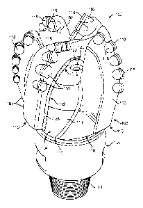
[0025] FIG. 2 illustrates one example of a fixed-cutter drill bit 100
having
one or more ductile inserts 126 disposed in the body 108 of the drill bit 100
and flush with the exterior portion thereof in accordance with the present
disclosure. The drill bit 100 can include a body 108 having a plurality of
blades 102 extending radially from a central portion of the body 108, each
being made of a metal-matrix composite material (described below). The
plurality of blades 102 can be integrally formed in and part of the body 108.
Respective fluid flow paths (also referred to as "junk slots") 124 can be
disposed between adjacent blades 102.
[0026] A proximal end of the drill bit 100 can include a plurality of
cutters
118 operable to engage downhole formation materials and remove such
materials to form a wellbore. Each cutter 118 can be disposed in respective
cutter pockets 116 formed on an exterior portion of respective blade 102.
Each cutter 118 can include respective cutting surface formed from hard
materials satisfactory for engaging and removing adjacent downhole
formation materials.
[0027] Cutters 118 can scrape and gouge formation materials from the
bottom and sides of a wellbore (not shown) during rotation of drill bit 100.
For some applications, various types of polycrystalline diamond compact
(PDC) cutters can be satisfactorily used as cutters 118. A drill bit having
PDC
cutters can sometimes be referred to as a "PDC bit".
[0028] One or more nozzle openings 120 can be formed in exterior
portions of the body 108. Respective nozzles 122 can be disposed in each
nozzle opening 120. Various types of drilling fluid may be pumped from
7
CA 02981003 2017-09-26
WO 2016/178693 PCT/US2015/029735
surface drilling equipment (shown in FIG. 1) through an associated drill
string 18 (shown in FIG. 1) attached to the threaded pin 114 of the shank or
106 to fluid flow passageway disposed within the body 108. One or more
fluid flow passageways can be formed in the body 108 to communicate
drilling fluid and/or other fluids to associated nozzles 120. See for example
fluid passageways 972 in FIG. 10.
[0029] A distal end of the body 108 of the drill bit 100 can include at
least one bevel 110. The bevel 110 can be placed at the distal end of a
blade 102 which protrudes from the central portion 104 of the body 108. The
bevel 110 can protrude from the central portion 104 of the body 108 further
than the shank 106 which is described below.
[0030] A distal end of the drill bit 101 can also include a shank 106
operable to releasably engage the drill bit 101 with a drill string (shown in
FIG. 1), bottom hole assembly (not shown) and/or a downhole drilling motor
(not shown) to rotate the drill bit 100 during formation of a borehole. Shank
106 and associated bit blank 36 (shown in FIG. 10) can be described as
having respective generally hollow cylindrical configurations defined in part
by a fluid flow passageway extending therethrough. Various types of
threaded connections such as American Petroleum Institute (API) drill pipe
connection or threaded pin 114 can be formed on the shank 106 proximate
the distal end of the drill bit 101.
[0031] The body 108, and its plurality of blades 102, can be made up of
a metal-matrix composite. The metal-matrix composite can include any
suitably hard material as the reinforcement material, such as tungsten
carbide, and any suitably ductile material as the matrix material, such as a
pure metal or metal alloy. For example, the metal-matrix composite can
include, but is not limited to, copper, nickel, cobalt, iron, aluminum,
molybdenum, chromium, manganese, tin, zinc, lead, silicon, tungsten,
boron, phosphorous, gold, silver, palladium, indium, any mixture thereof,
8
CA 02981003 2017-09-26
WO 2016/178693 PCT/US2015/029735
any alloy thereof, and any combination thereof. Non-limiting examples of
alloys of the binder material 324 may include copper-phosphorus, copper-
phosphorous-silver, copper-manganese-phosphorous, copper-nickel, copper-
manganese-nickel, copper-manganese-zinc, copper-manganese-nickel-zinc,
copper-nickel-indium, copper-tin-manganese-nickel, copper-tin-manganese-
nickel-iron, gold-nickel, gold-palladium-nickel, gold-copper-nickel, silver-
copper-zinc-nickel, silver-manganese, silver-copper-zinc-cadmium, silver-
copper-tin, cobalt-silicon-chromium-nickel-tungsten,
cobalt-silicon-
chromium-nickel-tungsten-boron, manganese-nickel-cobalt-boron, nickel-
silicon-chromium, nickel-chromium-silicon-manganese, nickel-chromium-
silicon, nickel-silicon-boron, nickel-silicon-chromium-boron-iron, nickel-
phosphorus, nickel-manganese, copper-aluminum, copper-aluminum-nickel,
copper-aluminum-nickel-iron, copper-aluminum-nickel-zinc-tin-iron, and the
like, and any combination thereof. The metal-matrix composite can also
include reinforcement particles.
[0032] The
reinforcement particles can include diamond or ceramic
materials such as carbides, nitrides, oxides, borides, and suicides, and
combinations thereof, such as carbonitrides. More specifically, the
reinforcement particles can include carbides made from elements such as
molybdenum, tungsten, chromium, titanium, niobium, vanadium, tantalum,
zirconium, hafnium, manganese, iron, nickel, boron, aluminum, and silicon .
Reinforcement particles can include borides made from elements such as
titanium, zirconium, hafnium, vanadium, niobium, tantalum, chromium,
molybdenum, tungsten, iron, cobalt, nickel, and lanthanum. Reinforcement
particles can include nitrides made from elements such as boron, silicon,
aluminum, iron, nickel, scandium, yttrium, titanium, vanadium, chromium,
zirconium, molybdenum, tungsten, tantalum, hafnium, manganese, and
niobium. Reinforcement particles can include oxides made from elements
such as silicon, aluminum, yttrium, zirconium, and titanium. By way of
9
CA 02981003 2017-09-26
WO 2016/178693 PCT/US2015/029735
example and not limitation, materials that can be used to form
reinforcement particles include tungsten carbide (WC, W2C), titanium carbide
(TiC), tantalum carbide (TaC), titanium diboride (TiB2), chromium carbides,
titanium nitride (TIN), vanadium carbide (VC), aluminum oxide (A1203),
aluminum nitride (AIN), boron nitride (BN), boron carbide (B4C), and silicon
carbide (SIC). In at least one example, when using Cu alloy materials as the
matrix, it is particularly desirable to use tungsten carbide particles in the
various morphologies described herein to form the metal-matrix composite.
Furthermore, combinations of different reinforcement particles can be used
to tailor the physical properties and characteristics of the metal-matrix
composite. The reinforcement particles can be formed using techniques
known to those of ordinary skill in the art. Most suitable materials for
reinforcement particles are commercially available and the formation of the
remainder is within the ability of one of ordinary skill in the art.
[0033] The
ductile inserts 126 are strategically positioned at locations of
the drill bit 100 that experience high stress. The ductile inserts 126
comprise
any of a variety of ductile materials selected for the intended application.
The selected ductile material of the ductile inserts 126 is more ductile than
the composite material making up the body 108 of the drill bit 100, for
example the metal-matrix composite body 108.
Ductility is generally
understood as the ability of a material to plastically deform before failure,
and can be determined during a standard materials test, such as a tensile
test. In particular, ductile materials undergo elastic deformation as well as
a
degree of plastic deformation before rupturing. On the other hand, brittle
materials undergo comparatively little and possibly negligible plastic
deformation before rupturing. One measure of ductility is elongation, or
strain (), which can be expressed as change in length (EL) per unit length
(L), or E =Li, . Another measure of ductility is toughness, which is defined
as
the area under the stress-strain curve and is a measure of the absorbed
CA 02981003 2017-09-26
WO 2016/178693 PCT/US2015/029735
plastic strain energy. Elongation and toughness can be determined by
standard tensile tests, such as ASTM E8 (for metallic materials), where the
selection of the particular test may depend on the particular material being
tested.
[0034] The ductile inserts 126 disclosed herein can be made up of a
ductile material with an elongation of at least 3% before rupture,
alternatively at least 6% before rupture, alternatively at least 10% before
rupture. For example, the ductile material herein may have an elongation
from 2 to 100% before rupture. In contrast, a non-ductile, or brittle,
material may have an elongation of less than 2% before rupture. In some
examples, the ductile material can have a ductility that is greater than 4
times the ductility of the metal-matrix composite of the body 108. For
example, the metal-matrix composite can have a ductility of less than 1%
before rupture while the ductile material can have a ductility of at least 4%
before rupture.
[0035] The ductile material can include any metal or alloy that exhibits
sufficient ductility compared to that of the metal-matrix composite material
and is refractory to (does not melt during) the infiltration process.
Depending on the processing temperature during manufacture, examples of
suitable materials include, but are not limited to, tungsten, rhenium,
osmium, tantalum, molybdenum, niobium, iridium, ruthenium, hafnium,
boron, rhodium, vanadium, chromium, zirconium, platinum, titanium,
lutetium, palladium, thulium, scandium, iron, yttrium, erbium, cobalt,
holmium, nickel, silicon, dysprosium, terbium, gadolinium, beryllium,
manganese, copper, samarium, gold, neodymium, silver, germanium,
praseodymium, lanthanum, and any alloy or combination thereof. Examples
of alloys include, but are not limited to, tantalum-tungsten, tantalum-
tungsten-molybdenum, tantalum-tungsten-rhenium, tantalum-tungsten-
molybdenum-rhenium, tantalum-tungsten-zirconium, tungsten-rhenium,
11
CA 02981003 2017-09-26
WO 2016/178693 PCT/US2015/029735
tungsten-molybdenum, tungsten-rhenium-
molybdenum, tungsten-
molybdenum-hafnium, tungsten-molybdenum-
zirconium, tungsten-
ruthenium, niobium-vanadium, niobium-vanadium-titanium, niobium-
zirconium, niobium-tungsten-zirconium, niobium-hafnium-titanium, niobium-
tungsten-hafnium, nickel-copper, nickel-chromium, nickel-chromium-iron,
nickel-chromium-molybdenum, nickel-molybdenum, HASTELLOY alloys
(i.e., nickel-chromium containing alloys, available from Haynes
International), INCONEL alloys (i.e., austenitic nickel-chromium containing
superalloys available from Special Metals Corporation), WASPALOYS (i.e.,
austenitic nickel-based superalloys), RENE alloys (i.e., nickel-chromium
containing alloys available from Altemp Alloys, Inc.), HAYNES alloys (i.e.,
nickel-chromium containing superalloys available from Haynes
International), MP98T (i.e., a nickel-copper-chromium superalloy available
from SPS Technologies), TMS alloys, CMSX alloys (i.e., nickel-based
superalloys available from C-M Group), cobalt alloy 6B (i.e., cobalt-based
superalloy available from HPA), and N-155 alloys.
[0036] The ductile inserts
126 can be disposed within the body 108. The
ductile inserts 126 can be exposed from the body 108 at one or more high-
stress portions of the drill bit 100. The ductile inserts 126 can be
substantially flush with the external surface of the body 108. When the
ductile inserts 126 are substantially flush with the external surface, the
external surface of the ductile inserts 126 is substantially aligned with the
external surface of the body 108. The high-stress portions of the drill bit
100
can be any portion where the drill bit 100 can crack or fail. The high-stress
portions of the drill bit 100 can be determined by at least one of modeling,
such as stress modeling, thermal modeling, thermo-mechanical modeling,
mechanical experience, operational experience, manufacturing experience,
test bits or coupons, or any suitable method to determine portions
experiencing high stress. For example, regarding operational experience, if a
12
CA 02981003 2017-09-26
WO 2016/178693 PCT/US2015/029735
portion of the drill bit 100 is regularly cracking, then ductile inserts 126
can
be disposed in the body 108 and exposed at the portion that is regularly
cracking.
[0037] FIGS. 2-6 illustrate example embodiments of drill bits with ductile
inserts exposed at various high-stress portions. The configurations of the
drill bit and the ductile inserts are not limited to the example embodiments
herein. Ductile inserts 126 can be exposed at the root 112 of the blade 102
as shown in FIG. 2. The root 112 of the blade 102 can be defined as the
portion where the blades 102 extend from the central portion 104 of the
body 108 and/or where the blade 102 meets the junk slot 124. The ductile
inserts 126 can be exposed at the root 112 of at least one blade 102 of the
drill bit 100. For example, the ductile inserts 126 can be exposed at the root
112 of multiple or every blade 102 of the drill bit 100. The ductile inserts
126 can be exposed at a portion of the blade 102, the junk slot 124, and/or
the root 112. The ductile inserts 126 can be exposed only at these portions
(e.g. only at the root 112), or the ductile inserts 126 can be exposed at an
area greater than these portions (e.g. an area greater than the root 112).
[0038] It will be understood that exposure of the ductile inserts 126 at a
particular portion or area as discussed herein includes also the substantially
immediate or proximate area around or near the discussed portion or area.
Additionally, the surfaces of the ductile inserts 126 that are not exposed may
have surface features formed thereon to promote bonding and adhesion
between the metal-matrix composite and ductile materials. Examples of such
features include dimples, divots, threads, recesses, grooves, channels,
protrusions, perforations, nubs, fins, knurling, castellations, any
combination
thereof, and the like.
[0039] Ductile inserts 126 can also be exposed at the bevel 110 as
shown in FIG. 3. As the bevel 110 protrudes from the central portion 104 of
the body 108, when the drill string 18 (shown in FIG. 1) is retracted, the
13
CA 02981003 2017-09-26
WO 2016/178693 PCT/US2015/029735
bevel 110 of the drill bit 100 can be impacted, causing damage such as
cracks or possible failure of the drill bit 100. Therefore, the ductile
inserts
126 can be exposed at the bevel 110 to prevent or mitigate damage to the
drill bit 100.
[0040] In other examples, ductile inserts 126 can be exposed at multiple
portions that experience high stress, as shown in FIG. 4. In the illustrated
embodiment, ductile inserts 126 are exposed at both the bevel 110 and the
root 112; in this embodiment, the root reinforcement is wider than that
shown in FIG. 2. Other high-stress portions can include the nozzle 122, the
nozzle threads (not shown), or the proximal portion of the body 108 where
the blades 102 converge (not shown).
[0041] Another high-stress portion can include the portion of the blades
102 that includes the cutters 118, as shown in FIG. 5. The cutters 118 and
the cutter pockets 116 can experience high stress while maneuvering
through and removing the downhole formation material. As such, ductile
inserts 126 can be exposed at the portion of the blade 102 surrounding the
cutters 118 and the cutter pockets 116. In the embodiment shown in FIG. 5,
the ductile insert 126 is localized to those cutter pockets 116 that protrude
most from the apex region of the drill bit 100.
[0042] To accommodate high-force loads, the ductile inserts 126 can be
interlinked, as shown in FIG. 6, such that the load on one portion will be
partially transferred amongst the linked portions, thereby sharing loads.
Doing so can mitigate stresses in situations where, for example, the drill bit
100 is experiencing high-force loads on a single blade 102 and the
interlinked ductile inserts 126 can reduce the chance of blade failure. In the
illustrated embodiment, the ductile inserts 126 are exposed at the blades
102 around the cutters 118 and the cutter pockets 116. The ductile inserts
126 are internally interlinked, which allows the loads to be transferred
substantially uniformly across all of the blades 102.
14
CA 02981003 2017-09-26
WO 2016/178693 PCT/US2015/029735
[0043] The ductile inserts 126 can be any shape or size to reduce or
eliminate cracking and failure to the drill bit 100 while maintaining the
function of the drill bit 100. The ductile inserts 126 can be thin and
provided
as substantially surface modifications. Alternatively, the ductile inserts 126
can be disposed deeper within the body 108 of the drill bit 100, similar to
the body of an iceberg under water. The ductile inserts 126 can be exposed
to the extent necessary to reduce or eliminate cracking and failure to the
drill bit 100 while maintaining the function of the drill bit 100. The ductile
inserts 126 can eliminate or reduce stress by being shaped to replace
portions of the metal-matrix composite bit body 108 that experience high
stresses. Locations of stress concentration can be identified by stress/strain
modeling, mechanical design handbooks, or design/manufacturing
experience. Examples of stress-concentrating features or geometries include
sharp corners, such as the threads in nozzle channels, nozzle channel-to-
landing transition, or blade bevels.
[0044] With knowledge of the stress and/or strain experienced in certain
regions of the metal-matrix composite bit body 108, the ductile inserts 126
can be shaped, sized, and positioned at the portions that experience high
stresses. As such, the drill bit 100 has increased ductility and crack
resistance at typical high-stress portions without sacrificing the amount of
erosion-resistant particles at and near the surfaces of the drill bit 100.
[0045] Examples of the size, shape, and depth of ductile inserts 126 are
shown in FIGS. 7-9. FIG. 7 illustrates the drill bit 100 of FIG. 2. However,
FIG. 7 shows ductile inserts 126 that are disposed within the body 108 of the
drill bit 100 while being exposed at the high-stress portions, for example the
root 112. The ductile inserts 126 are also substantially flush with the
external surface of the body 108 where exposed. As shown in FIG. 7, the
ductile insert can be made of a material different than the material of the
body 108 of the drill bit 100.
CA 02981003 2017-09-26
WO 2016/178693 PCT/US2015/029735
[0046] The ductile inserts 126 can be shaped and sized in a variety of
manners, such as to be substantially similar to the shape and size of the
portions that experience stress; to displace a suitable amount of composite
material, which may reduce costs; or to provide interlocking or increased
surface area between the composite and insert materials. In the illustrated
embodiment of FIG. 8, the ductile inserts 126 are substantially a triangular
shape. In the illustrated embodiment of FIG. 9, the ductile inserts 126 are
substantially a bulb shape. However, the ductile inserts 126 can be any
shape of size that is suitable for reducing or eliminating cracking and
failure
of the drill bit 100. The ductile inserts 126 can be exposed substantially at
the root 112 of the blade 102. Where exposed, the ductile inserts 126 can be
substantially flush with the external surface of the body 108 of the drill bit
100. As such, the exposed end of the ductile inserts 126 are substantially
aligned with the external surface of the body 108 of the drill bit 100.
Minimization of the exposed external surface of the ductile insert 126 can
maintain a suitably high stiff and erosion-resistant outer surface while
providing crack resistance during manufacture or operation.
[0047] When manufacturing a drill bit, a mold assembly can be used.
FIG. 10 is a cross-sectional view illustrating a mold assembly with inserts
126 and a metal-matrix composite forming a body 108 of a drill bit 100.
Mold assembly 900 as shown in FIG. 10 can include several components
such as a mold 902, a gauge ring or connector ring 904, and a funnel 920.
Mold 902, gauge ring 904, and funnel 920 can be formed from graphite or
other suitable materials. Various techniques may be used including, but not
limited to, machining a graphite blank to form mold cavity 952 having a
negative profile or a reverse profile of desired exterior features for a
resulting fixed-cutter drill bit. For example mold cavity 954 may have a
negative profile which corresponds with the exterior profile or configuration
of blades 102 and junk slots 124 as shown in FIG. 2.
16
CA 02981003 2017-09-26
WO 2016/178693 PCT/US2015/029735
[0048] Various types of temporary displacement materials and mold
inserts can be installed within mold cavity 952 depending on the desired
configuration of a resulting matrix drill bit 100. For example mold inserts
can
be formed from various materials such as consolidated sand and/or graphite
and may be disposed within mold cavity. Various resins can be satisfactorily
used to form consolidated sand. Mold inserts can have configurations and
dimensions corresponding with desired features of body 108 such as cutter
pockets 116 formed in blades 102. The dimensions and configuration of mold
inserts and associated cutter pockets 116 may be selected to correspond
with desired dimensions and configuration for cutters 118 in respective
blades 102.
[0049] Displacement materials such as consolidated sand can be installed
within mold assembly 900 at desired locations to form portions of cavity 952
and fluid flow passages 972 extending therefrom. The orientation and
configuration of consolidated sand legs 172 can be selected to correspond
with desired locations and configurations of associated fluid flow
passageways 972 communicating from cavity 952 to respective nozzles 122.
Further, in the illustrated embodiment, a junk slot displacement 496 can
correspond with the junk slots 124 as shown in FIG. 2.
[0050] A relatively large, generally cylindrically shaped consolidated sand
core 150 can be placed on the legs 172. The number of legs extending from
sand core 150 will depend upon the desired number of nozzle openings in a
resulting body.
[0051] Ductile inserts 126 can be installed within mold assembly 900 at
desired locations while being exposed and flush with the external surface of
the body 108 of the drill bit 100. The ductile insert 126 shown in FIG. 10
illustrates an insert placed in a blade bevel region. Alternatively, the
ductile
insert 126 may be placed at other locations in the mold assembly 900, such
as at or near the blade root, nozzle channel, nozzle threads, cutter pockets,
17
CA 02981003 2017-09-26
WO 2016/178693 PCT/US2015/029735
and blade standoffs. The ductile inserts 126 can be pre-formed. The ductile
inserts 126 can be installed within the mold assembly 900 by any suitable
methods. For example, a person can manually hold the ductile inserts 126 at
the desired locations. As another example, various fixtures (not shown) can
be used to position the ductile inserts 126 within the mold assembly 900 at
the desired locations. The ductile inserts 126 can be positioned before,
during, or after placement of the reinforcement material 131 described
below. Alternatively, the ductile inserts 126 can be formed to extend past
the final surface of the body 108 such that the ductile inserts 126 can be
machined to be flush with the final surface of the body 108 in a subsequent
operation.
[0052] After desired displacement materials, including core 150 and legs
172, have been installed within mold assembly 900, reinforcement material
131 having desired characteristics for the body 108 can be placed within
mold assembly 900. The exemplary reinforcement material 131 can be
tungsten carbide. The present disclosure allows the use of reinforcement
materials having characteristics of toughness and wear resistance for
forming a fixed-cutter drill bit.
[0053] A generally hollow, cylindrical bit blank 36 can be placed within
mold assembly 900. Bit blank 36 can include an inside diameter 37 which is
larger than the outside diameter of the core 150. Various fixtures (not
shown) can be used to position bit blank 36 within mold assembly 900 at a
desired location spaced from reinforcement material 131.
[0054] The shoulder material 132, such as tungsten powder, can be
placed in mold assembly 900 between exterior portions of bit blank 36 and
adjacent interior portions of funnel 920. Shoulder material 132 can be a
relatively soft powder which forms a matrix that may subsequently be
machined to provide a desired exterior configuration and transition between
body 108 and bit blank 36.
18
CA 02981003 2017-09-26
WO 2016/178693 PCT/US2015/029735
[0055] Reinforcement material 131 can be reinforcement particles such
as cemented carbides and/or spherical carbides. Alloys of cobalt, iron,
and/or nickel can be used as an infiltration aid.
[0056] A typical infiltration process for forming the body 108 can begin
by forming mold assembly 900. Gage ring 904 can be threaded onto the top
of mold 902. Displacement materials such as, but not limited to, ductile
inserts 126, legs 172, and sand core 150 can then be loaded into mold
assembly 900 if not previously placed in mold cavity 952. Reinforcement
material 131, shoulder material 132, and bit blank 36 can be loaded into
mold assembly 900. Funnel 920 can be threaded onto the top of gage ring
904 to extend mold assembly 900 to a desired height to hold reinforcement
material 131, shoulder material 132, and binding material 160.
[0057] As mold assembly 900 is being filled with reinforcement material
131 and shoulder material 132, a series of vibration cycles can be induced in
mold assembly 900 to assist desired distribution of each layer or zone of
reinforcement material 131 and shoulder material 132. Vibrations help to
ensure consistent and compacted density of each layer of reinforcement
material 131 and shoulder material 132 within respective ranges required to
achieve desired characteristics for the body 108. As such, the vibrations can
help compact the reinforcement material 131 and shoulder material 132
within the mold assembly 900.
[0058] Binding material 160 can be placed on top of layer 132, bit blank
36 and core 150. Binding material 160 may be covered with a flux layer (not
expressly shown). A cover or lid (not shown) can be placed over mold
assembly 900. Mold assembly 900 and materials disposed therein can be
preheated and then placed in a furnace (not shown). When the furnace
temperature reaches the melting point of binding material 160, liquid
binding material 160 can infiltrate reinforcement material 131 and shoulder
material 132. The ductile material of the ductile inserts 126 can have a
19
CA 02981003 2017-09-26
WO 2016/178693 PCT/US2015/029735
melting point greater than the melting point of the binding material 160. As
such, the ductile inserts 126 do not melt in the process.
[0059] Mold assembly 900 can then be removed from the furnace and
cooled at a controlled rate. The body 108 of the drill bit 100 then includes a
metal-matrix composite with at least one ductile insert 126 partially
disposed within the metal-matrix composite. Once cooled, mold assembly
900 can be broken away to expose the body 108.
[0060] Referring to FIG. 11, a flowchart is presented in accordance with
an example embodiment. The method 1000 is provided by way of example,
as there are a variety of ways to carry out the method. The method 1000
described below can be carried out using the configurations illustrated in
FIGS. 1-10, for example, and various elements of these figures are
referenced in explaining example method 1000. Each block shown in FIG.
11 represents one or more processes, methods, or subroutines, carried out
in the example method 1000. Furthermore, the illustrated order of blocks is
illustrative only and the order of the blocks can change according to the
present disclosure. Additional blocks may be added or fewer blocks may be
utilized, without departing from this disclosure. The example method 1000
can begin at block 1002.
[0061] At block 1002, a mold can be provided. The mold can be coupled
to a gage ring. The gage ring can be coupled to a funnel. The mold can
define a body of the drill bit.
[0062] At block 1004, at least one ductile insert can be positioned within
the mold. The ductile inserts can be made of a material that has a ductility
greater than a ductility of the material of the body. For example, the ductile
inserts can be made of iron. The ductile inserts can be pre-formed, where
the ductile inserts are formed before being positioned within the mold. The
ductile inserts can be positioned such that the ductile inserts are disposed
within the body of the drill bit, but also exposed and flush with the external
CA 02981003 2017-09-26
WO 2016/178693 PCT/US2015/029735
surface of the body. The ductile inserts can further be positioned such that
the ductile inserts are exposed at high-stress portions of the drill bit,
which
can be determined by at least one of modeling, such as stress modeling,
thermal modeling, thermo-mechanical modeling, mechanical experience,
operational experience, manufacturing experience, test bits or coupons, or
any suitable method to determine portions experiencing high stress. The
ductile inserts can be interlinked with ductile material. Various fixtures can
be used to position the ductile inserts within the mold at the desired
locations.
[0063] At block 1006, reinforcement particles can be inserted into the
mold. The reinforcement particles can be any suitable material as described
above. For example, the reinforcement particles can be tungsten carbide.
The reinforcement particles can be inserted around the ductile inserts.
[0064] At block 1008, the reinforcement particles can be compacted. The
reinforcement particles can be compacted by vibration, which also can assist
in achieving a desired distribution of the reinforcement particles. The
compacting of the reinforcement particles also helps secure the positioning
of the ductile inserts.
[0065] At block 1010, the reinforcement particles can be infiltrated with a
binding material. The binding material can be heated such that the binding
material melts and flows into the compacted mass of reinforcement
particles. The binding material can be any suitable material as described
above, for example a copper-nickel alloy. The binding material can have a
melting point lower than the melting points of the ductile inserts and the
reinforcement particles. The infiltration of the reinforcement particles with
the binding material can form a metal-matrix composite. The binding
material also surrounds the ductile inserts.
[0066] At block 1012, the metal-matrix composite can be cooled to
solidify the metal-matrix composite and form the body of the drill bit. As
21
CA 02981003 2017-09-26
WO 2016/178693 PCT/US2015/029735
such, the body can include the ductile inserts disposed within the body while
being exposed and flush with the external surface at high-stress portions.
Once cooled, the mold can be broken away to expose the body.
[0067] Numerous examples are provided herein to enhance
understanding of the present disclosure. A specific set of examples are
provided as follows.
[0068] In a
first example, there is disclosed a fixed-cutter drill bit
including: a metal-matrix composite body having at least one metal-matrix
composite blade formed in the body; a plurality of cutters disposed on the at
least one metal-matrix composite blade; and a ductile insert partially
disposed within the metal-matrix composite body and having an exposed
surface, wherein the ductile insert has a greater ductility than the metal-
matrix composite body.
[0069] In a
second example, a fixed-cutter drill bit is disclosed according
to the preceding example, wherein the exposed surface of the ductile insert
is flush with an external surface of the metal-matrix composite body.
[0070] In a
third example, a fixed-cutter drill bit is disclosed according to
any of the preceding examples, wherein the exposed surface of the ductile
insert is positioned at or proximate to at least one high-stress portion of
the
fixed-cutter drill bit.
[0071] In a
fourth example, a fixed-cutter drill bit is disclosed according
to any of the preceding examples, wherein the exposed surface is located at
or proximate to a root portion of the at least one metal-matrix composite
blade, the root portion being the portion where the at least one metal-matrix
composite blade extends from a central portion of the metal-matrix
composite body.
[0072] In a
fifth example, a fixed-cutter drill bit is disclosed according to
any of the preceding examples, wherein the metal-matrix composite body
comprises a proximal portion having the at least one metal-matrix composite
22
CA 02981003 2017-09-26
WO 2016/178693 PCT/US2015/029735
blade, and a distal portion having a bevel, the exposed surface of the ductile
insert being located at or proximate to the bevel.
[0073] In a sixth example, a fixed-cutter drill bit is disclosed according
to
any of the preceding examples, wherein the metal-matrix composite body
includes at least one of a plurality of cutter pockets corresponding to the
plurality of cutters, a nozzle channel, a nozzle thread, or a blade standoff,
wherein a ductile insert provided at or proximate to at least one of the
plurality of cutter pockets corresponding to the plurality of cutters, the
nozzle channel, the nozzle thread, or the blade standoff.
[0074] In a seventh example, a fixed-cutter drill bit is disclosed
according
to any of the preceding examples, wherein the ductile insert comprises a
metal or a metal alloy.
[0075] In an eighth example, a fixed-cutter drill bit is disclosed
according
to any of the preceding examples, wherein the ductile insert exhibits an
elongation of at least 3% without rupture.
[0076] In a ninth example, a fixed-cutter drill bit is disclosed according
to
any of the preceding examples, wherein the ductile insert can realize an
elongation of at least 10% without rupture.
[0077] In a tenth example, a fixed-cutter drill bit is disclosed according
to
any of the preceding examples, wherein the metal-matrix composite
material making up the metal-matrix composite body and metal-matrix
composite blade exhibits an elongation of less than 2% before rupture.
[0078] In an eleventh example, a fixed-cutter drill bit is disclosed
according to any of the preceding examples, wherein the metal-matrix
composite body includes tungsten carbide.
[0079] In a twelfth example, a system is disclosed including a drill string
provided in a wellbore, the drill string having a downhole drilling device
with
a drill bit disposed on its lower end; and the drill bit including: a metal-
matrix composite body having at least one metal-matrix composite blade; a
23
CA 02981003 2017-09-26
WO 2016/178693 PCT/US2015/029735
plurality of cutters disposed on the at least one metal-matrix composite
blade; and a ductile insert partially disposed within the metal-matrix
composite body and having an exposed surface, wherein the ductile insert
has a greater ductility than the metal-matrix composite body.
[0080] In a thirteenth example, a system is disclosed according to the
twelfth example, wherein the exposed surface of the ductile insert is flush
with an external surface of the metal-matrix composite body.
[0081] In a fourteenth example, a system is disclosed according to the
twelfth or thirteenth examples, wherein the exposed surface of the ductile
insert is positioned at or proximate to at least one high-stress portion of
the
fixed-cutter drill bit.
[0082] In a fifteenth example, a system is disclosed according to any of
the preceding twelfth to the fourteenth examples, wherein the exposed
surface is located at or proximate to a root portion of the at least one
blade,
the root portion being the portion where the at least one blade extends from
a central portion of the metal-matrix composite body.
[0083] In a sixteenth example, a system is disclosed according to any of
the preceding twelfth to the fifteenth examples, wherein the metal-matrix
composite body has a proximal portion having the at least one metal-matrix
composite blade, and a distal portion having a bevel, the exposed surface of
the ductile insert being located at or proximate the bevel.
[0084] In a seventeenth example, a system is disclosed according to any
of the preceding twelfth to the sixteenth examples, wherein the ductile insert
includes a metal or a metal alloy.
[0085] In an eighteenth example, a system is disclosed according to any
of the preceding twelfth to the seventeenth examples, wherein the ductile
insert exhibits an elongation of at least 3% without rupture.
[0086] In a nineteenth example, a system is disclosed according to any
of the preceding twelfth to the eighteenth examples, wherein the metal-
24
CA 02981003 2017-09-26
WO 2016/178693 PCT/US2015/029735
matrix composite material making up the metal-matrix composite body and
metal-matrix composite blade exhibits an elongation of less than 2% before
rupture.
[0087] In a
twentieth example, a system is disclosed according to any of
the preceding twelfth to the nineteenth examples, wherein the metal-matrix
composite body includes tungsten carbide.
[0088] The
embodiments shown and described above are only
examples. Even though numerous characteristics and advantages of the
present technology have been set forth in the foregoing description, together
with details of the structure and function of the present disclosure, the
disclosure is illustrative only, and changes may be made in the detail,
especially in matters of shape, size and arrangement of the parts within the
principles of the present disclosure to the full extent indicated by the broad
general meaning of the terms used in the attached claims. It will therefore
be appreciated that the embodiments described above may be modified
within the scope of the appended claims.