Note: Descriptions are shown in the official language in which they were submitted.
CA 02981985 2017-10-05
WO 2016/191091 PCT/US2016/031587
1
CONTROL FLOW ENHANCEMENTS FOR LTE-UNLICENSED
CROSS REFERENCES
[00011 The present Application for Patent claims priority to U.S. Patent
Application
No. 15/149,752 by Yerramalli et al., entitled "Control Flow Enhancements for
LTE-
Unlicensed," filed May 9, 2016; and U.S. Provisional Patent Application No.
62/165,814 by
Yerramalli et al., entitled "Control Flow Enhancements for LTE-Unlicensed,"
filed May 22,
2015; each of which is assigned to the assignee hereof.
BACKGROUND
[00021 The following relates generally to wireless communication, and
more specifically
to control flow enhancements for LTE-Unlicensed.
[00031 Wireless communications systems are widely deployed to provide
various types of
communication content such as voice, video, packet data, messaging, broadcast,
and so on.
These systems may be capable of supporting communication with multiple users
by sharing
the available system resources (e.g., time, frequency, and power). Examples of
such multiple-
access systems include code division multiple access (CDMA) systems, time
division
multiple access (TDMA) systems, frequency division multiple access (FDMA)
systems, and
orthogonal frequency division multiple access (OFDMA) systems, (e.g., an LTE
system). A
wireless multiple-access communications system may include a number of base
stations, each
simultaneously supporting communication for multiple communication devices,
which may
be otherwise known as user equipment (UE).
[00041 In an LTE or LTE-Advanced (LTE-A) network, a base station and a UE may
communicate over dedicated frequency spectrum that is licensed to the network
operator. A
licensed operator network (e.g., cellular network, etc.) may be known as a
public land mobile
network (PLMN). With increasing data traffic in cellular networks that use
dedicated (e.g.,
licensed) radio frequency bands, offloading at least some data traffic to
unlicensed or shared
radio frequency spectrum may enhance data transmission capacity and efficient
use of
resources. Unlicensed and shared radio frequency spectrum may also provide
service in areas
where access to a dedicated radio frequency spectrum is unavailable.
Unlicensed spectrum
generally refers to spectrum available for use without a license and is
typically subject to
CA 02981985 2017-10-05
WO 2016/191091 PCT/US2016/031587
2
technical rules regarding access and transmitted power. Shared spectrum
generally refers to
spectrum that is available to devices associated with one of multiple
operators
[0005] A listen before talk (LBT) procedure may be used for contention
resolution for
access to shared frequency resources of licensed or unlicensed frequency
spectrum without
pre-coordinated resource allocation. An LBT procedure may include performing a
clear
channel assessment (CCA) procedure to deteimine whether a shared channel is
available.
When it is determined that the shared channel is available, a device may
transmit a signal to
reserve the channel before data transmissions. Other devices may monitor for
the reservation
signal to detect transmissions, and may also monitor the shared channel using
energy
detection to determine whether the shared channel is busy or free
[0006] Operation using LTE signal waveforms over the shared radio frequency
spectrum
may be called LTE-Unlicensed (LTE-U) operation, and an LTE device supporting
LTE-U
operation may be called an LTE-U device. Operation using LTE/LTE-A carriers in
unlicensed or shared frequency spectrum may be used in a standalone operation
mode where
an LTE/LTE-A carrier can be used as a primary cell for a UE. The LTE/LTE-A
carrier may
also be used in a licensed assisted access (LAA) mode where a UE is configured
with a
primary cell in a LTE/LTE-A carriers in unlicensed or shared frequency
spectrum are
configured as secondary cells in a carrier aggregation mode.
[0007] Because unlicensed cells (e.g., standalone or LAA) operating in
unlicensed or
shared frequency spectrum may be subject to LBT procedures, control flow
management
procedures designed around predetermined timing for dedicated spectrum may be
subject to
unpredictable timing variations. In addition, unlicensed or shared frequency
spectrum may
have additional restrictions that place limitations on transmission power or
duration that can
affect control flow management for unlicensed cells.
SUMMARY
[0008] Systems, methods, and apparatuses for control flow enhancement for
LTE-U
operation. Aspects include enhancements to control flow processing for
floating transmission
time interval (TTI) operation in unlicensed cells including enhanced physical
downlink
control channel (ePDCCH) processing, aperiodic channel state information (CSI)
reporting,
discontinuous reception (DRX) operation, and extended TTIs at the end of a
transmission
CA 02981985 2017-10-05
WO 2016/191091 PCT/US2016/031587
3
burst. The described aspects also include enhancements for reference signal
configuration for
unlicensed cells, processing of joint grants for multiple unlicensed cells,
ePDCCH processing
for partial subframes, and multi-channel DRS operation
[0009] A method of wireless communication is described. The method may
include
identifying a configuration for communication using a secondary cell in a
shared frequency
spectrum band, wherein transmissions via the secondary cell are subject to a
listen-before-
talk (LBT) procedure for a shared frequency channel, identifying a
transmission from the
secondary cell comprising of at least one subframe, and determining a
reference signal
configuration for the transmission based at least in part on a cross-subframe
indicator of at
least one subframe.
[0010] An apparatus for wireless communication is described. The
apparatus may include
means for identifying a configuration for communication using a secondary cell
in a shared
frequency spectrum band, wherein transmissions via the secondary cell are
subject to a listen-
before-talk (LBT) procedure for a shared frequency channel, means for
identifying a
transmission from the secondary cell comprising of at least one subframe, and
means for
determining a reference signal configuration for the transmission based at
least in part on a
cross-subframe indicator of at least one subframe.
[0011] A further apparatus for wireless communication is described. The
apparatus may
include a processor, memory in electronic communication with the processor,
and
instructions stored in the memory and operable, when executed by the
processor, to cause the
apparatus to identify a configuration for communication using a secondary cell
in a shared
frequency spectrum band, wherein transmissions via the secondary cell are
subject to a listen-
before-talk (LBT) procedure for a shared frequency channel, identify a
transmission from the
secondary cell comprising of at least one subframe, and determine a reference
signal
configuration for the transmission based at least in part on a cross-subframe
indicator of at
least one subframe.
[0012] A non-transitory computer-readable medium storing code for
wireless
communication is described. The code may include instructions executable to
identify a
configuration for communication using a secondary cell in a shared frequency
spectrum band,
wherein transmissions via the secondary cell are subject to a listen-before-
talk (LBT)
procedure for a shared frequency channel, identify a LBT transmission from the
secondary
CA 02981985 2017-10-05
WO 2016/191091 PCT/US2016/031587
4
cell comprising of at least one subframe, and determine a reference signal
configuration for
the transmission based at least in part on a cross-subframe indicator of at
least one subframe.
[0013] In some examples of the method, apparatuses, or non-transitory
computer-
readable medium described herein, the determining comprises identifying a set
of initially
transmitted subframes associated with at least one reference signal
configuration.
[0014] In some examples of the method, apparatuses, or non-transitory
computer-
readable medium described herein, the reference signal subframe indicator is
received over a
licensed cell operating in a dedicated frequency spectrum band.
[0015] In some examples of the method, apparatuses, or non-transitory
computer-
readable medium described herein, the reference signal subframe indicator
comprises a field
of a downlink control information (DCI) format received via a downlink control
channel of
the licensed cell. Additionally or alternatively, in some examples the
reference signal
subframe indicator is received over the secondary cell in an indicator channel
or a field of a
downlink control information (DCI) format received via a downlink control
channel of the
secondary cell.
[0016] Some examples of the method, apparatuses, or non-transitory
computer-readable
medium described herein may further include processes, features, means, or
instructions for
identifying that at least one subframe has asynchronous symbol timing relative
to a licensed
cell operating in a dedicated frequency spectrum band, and determining one or
more symbol
positions within the at least one subframe for at least one reference signal
based at least in
part on a detected symbol preamble associated with the transmission.
[0017] A method of wireless communication is described. The method may
include
identifying a plurality of cells in a transmission from a base station on a
shared frequency
spectrum band, wherein the transmission is subject to a listen-before-talk
(LBT) procedure
for a shared frequency channel, identifying a first scheduling configuration
for a first, initially
transmitted set of subframes of the transmission, the first scheduling
configuration
comprising one or more search spaces of a first set of cells configured for
carrying individual
grants for respective cells of the plurality of cells, and identifying a
second scheduling
configuration for a second set of subframes of the transmission subsequent to
the first set of
CA 02981985 2017-10-05
WO 2016/191091
PCT/US2016/031587
subframes, the second scheduling configuration comprising at least one search
space of at
least one cell associated with joint grants for the plurality of cells
[0018] An apparatus for wireless communication is described. The
apparatus may include
means for identifying a plurality of cells in a transmission from a base
station on a shared
5 frequency spectrum band, wherein the transmission is subject to a listen-
before-talk (LBT)
procedure for a shared frequency channel, means for identifying a first
scheduling
configuration for a first, initially transmitted set of subframes of the
transmission, the first
scheduling configuration comprising one or more search spaces of a first set
of cells
configured for carrying individual grants for respective cells of the
plurality of cells, and
means for identifying a second scheduling configuration for a second set of
subframes of the
transmission subsequent to the first set of subframes, the second scheduling
configuration
comprising at least one search space of at least one cell associated with
joint grants for the
plurality of cells.
[0019] A further apparatus for wireless communication is described. The
apparatus may
include a processor, memory in electronic communication with the processor,
and
instructions stored in the memory and operable, when executed by the
processor, to cause the
apparatus to identify a plurality of cells in a transmission from a base
station on a shared
frequency spectrum band, wherein the transmission is subject to a listen-
before-talk (LBT)
procedure for a shared frequency channel, identify a first scheduling
configuration for a first,
initially transmitted set of subframes of the transmission, the first
scheduling configuration
comprising one or more search spaces of a first set of cells configured for
carrying individual
grants for respective cells of the plurality of cells, and identify a second
scheduling
configuration for a second set of subframes of the transmission subsequent to
the first set of
subframes, the second scheduling configuration comprising at least one search
space of at
least one cell associated with joint grants for the plurality of cells.
[0020] A non-transitory computer-readable medium storing code for
wireless
communication is described. The code may include instructions executable to
identify a
plurality of cells of a shared frequency spectrum band, wherein the
transmission is subject to
a listen-before-talk (LBT) procedure for a shared frequency channel, identify
a first
scheduling configuration for a first, initially transmitted set of subframes
of the transmission,
the first scheduling configuration comprising one or more search spaces of a
first set of cells
CA 02981985 2017-10-05
WO 2016/191091
PCT/US2016/031587
6
configured for carrying individual grants for respective cells of the
plurality of cells, and
identify a second scheduling configuration for a second set of subframes of
the transmission
subsequent to the first set of subframes, the second scheduling configuration
comprising at
least one search space of at least one cell associated with joint grants for
the plurality of cells.
[0021] Some examples of the method, apparatuses, or non-transitory computer-
readable
medium described herein may further include processes, features, means, or
instructions for
determining a subset of the plurality of cells having associated frequency
channels
successfully reserved for the transmission. Additionally or alternatively,
some examples may
include processes, features, means, or instructions for determining the at
least one cell from
the subset of the plurality of cells based at least in part on a UE-specific
identifier.
[0022] In some examples of the method, apparatuses, or non-transitory
computer-
readable medium described herein, the at least one cell comprises a licensed
cell operating in
a dedicated frequency spectrum band.
[0023] A method of wireless communication is described. The method may
include
identifying a configuration for communication using a secondary cell in a
shared frequency
spectrum band, wherein transmissions via the secondary cell are subject to a
listen-before-
talk (LBT) procedure for a shared frequency channel, identifying a
transmission from the
secondary cell comprising of at least one subframe; and receiving an indicator
specifying a
foi __ mat of a partial subframe contained within the transmission.
[0024] An apparatus for wireless communication is described. The apparatus
may include
means for identifying a configuration for communication using a secondary cell
in a shared
frequency spectrum band, wherein transmissions via the secondary cell are
subject to a listen-
before-talk (LBT) procedure for a shared frequency channel, means for
identifying a
transmission from the secondary cell comprising of at least one subframe; and
means for
receiving an indicator specifying a format of a partial subframe contained
within the
transmission.
[0025] A further apparatus for wireless communication is described. The
apparatus may
include a processor, memory in electronic communication with the processor,
and
instructions stored in the memory and operable, when executed by the
processor, to cause the
apparatus to identify a configuration for communication using a secondary cell
in a shared
CA 02981985 2017-10-05
WO 2016/191091
PCT/US2016/031587
7
frequency spectrum band, wherein transmissions via the secondary cell are
subject to a listen-
before-talk (LBT) procedure for a shared frequency channel, identify a
transmission from the
secondary cell comprising of at least one subframe; and receive an indicator
specifying a
format of a partial subframe contained within the transmission.
[0026] A non-transitory computer-readable medium storing code for wireless
communication is described. The code may include instructions executable to
identify a
configuration for communication using a secondary cell in a shared frequency
spectrum band,
wherein transmissions via the secondary cell are subject to a listen-before-
talk (LBT)
procedure for a shared frequency channel, identify a transmission from the
secondary cell
comprising of at least one subframe; and receive an indicator specifying a
format of a partial
subframe contained within the transmission.
[0027] A method of wireless communication is described. The method may
include
estimating channel demodulation information from a limited set of antenna
ports associated
with a control channel for one or more cells of a shared frequency spectrum
band,
determining a control channel search space comprising a partial subframe for
the one or more
cells, and demodulating control channel candidates in the control channel
search space using
the channel demodulation information estimated from the limited set of antenna
ports.
[0028] An apparatus for wireless communication is described. The
apparatus may include
means for estimating channel demodulation information from a limited set of
antenna ports
associated with a control channel for one or more cells of a shared frequency
spectrum band,
means for determining a control channel search space comprising a partial
subframe for the
one or more cells, and means for demodulating control channel candidates in
the control
channel search space using the channel demodulation information estimated from
the limited
set of antenna ports.
[0029] A further apparatus for wireless communication is described. The
apparatus may
include a processor, memory in electronic communication with the processor,
and
instructions stored in the memory and operable, when executed by the
processor, to cause the
apparatus to estimate channel demodulation information from a limited set of
antenna ports
associated with a control channel for one or more cells of a shared frequency
spectrum band,
determine a control channel search space comprising a partial subframe for the
one or more
CA 02981985 2017-10-05
WO 2016/191091
PCT/US2016/031587
8
cells, and demodulate control channel candidates in the control channel search
space using
the channel demodulation information estimated from the limited set of antenna
ports.
[0030] A non-transitory computer-readable medium storing code for
wireless
communication is described. The code may include instructions executable to
estimate
channel demodulation information from a limited set of antenna ports
associated with a
control channel for one or more cells of a shared frequency spectrum band,
determine a
control channel search space comprising a partial subframe for the one or more
cells, and
demodulate control channel candidates in the control channel search space
using the channel
demodulation information estimated from the limited set of antenna ports.
[0031] In some examples of the method, apparatuses, or non-transitory
computer-
readable medium described herein, the control channel comprises a EPDCCH.
[0032] A method of wireless communication is described. The method may
include
identifying a configuration for communication using a synchronized cell, the
synchronized
cell operating in a shared frequency spectrum band and having static subframe
positions,
identifying a LBT transmission for the synchronized cell, determining a
dynamic TTI for a
shared data channel for the synchronized cell based at least in part on a
channel reservation
signal of the LBT transmission, and determining a search space for a control
channel within a
shared data region comprising the shared data channel based at least in part
on an offset
between the dynamic TTI and a boundary of the static subframe positions
[0033] An apparatus for wireless communication is described. The apparatus
may include
means for identifying a configuration for communication using a synchronized
cell, the
synchronized cell operating in a shared frequency spectrum band and having
static subframe
positions, means for identifying a LBT transmission for the synchronized cell,
means for
determining a dynamic TTI for a shared data channel for the synchronized cell
based at least
in part on a channel reservation signal of the LBT transmission, and means for
determining a
search space for a control channel within a shared data region comprising the
shared data
channel based at least in part on an offset between the dynamic TTI and a
boundary of the
static subframe positions.
[0034] A further apparatus for wireless communication is described. The
apparatus may
include a processor, memory in electronic communication with the processor,
and
CA 02981985 2017-10-05
WO 2016/191091 PCT/US2016/031587
9
instructions stored in the memory and operable, when executed by the
processor, to cause the
apparatus to identify a configuration for communication using a synchronized
cell, the
synchronized cell operating in a shared frequency spectrum band and having
static subframe
positions, identify a LBT transmission for the synchronized cell, determine a
dynamic TTI
for a shared data channel for the synchronized cell based at least in part on
a channel
reservation signal of the LBT transmission, and determine a search space for a
control
channel within a shared data region comprising the shared data channel based
at least in part
on an offset between the dynamic TTI and a boundary of the static subframe
positions.
[0035] A non-transitory computer-readable medium storing code for
wireless
communication is described. The code may include instructions executable to
identify a
configuration for communication using a synchronized cell, the synchronized
cell operating
in a shared frequency spectrum band and having static subframe positions,
identify a LBT
transmission for the synchronized cell, determine a dynamic TTI for a shared
data channel for
the synchronized cell based at least in part on a channel reservation signal
of the LBT
transmission, and determine a search space for a control channel within a
shared data region
comprising the shared data channel based at least in part on an offset between
the dynamic
TTI and a boundary of the static subframe positions.
[0036] In some examples of the method, apparatuses, or non-transitory
computer-
readable medium described herein, the search space comprises a same set of
symbols as the
dynamic TTI. Additionally or alternatively, in some examples the search space
comprises a
subset of symbols of the dynamic TTI, and wherein the subset of symbols of the
dynamic TTI
is determined based at least in part on the offset between the dynamic TTI and
the boundary
of the static subframe positions.
[0037] In some examples of the method, apparatuses, or non-transitory
computer-
readable medium described herein, the control channel comprises an enhanced
physical
downlink control channel (ePDCCH). Additionally or alternatively, some
examples may
include processes, features, means, or instructions for determining a number
of symbol
periods of a last TTI of the LBT transmission based at least in part on a
field included in at
least one of a physical frame format indication channel (PFFICH) or a grant
received in the
control channel.
CA 02981985 2017-10-05
WO 2016/191091 PCT/US2016/031587
[0038] Some examples of the method, apparatuses, or non-transitory
computer-readable
medium described herein may further include processes, features, means, or
instructions for
determining the search space for the control channel for the last TTI based at
least in part on
at least one of a static number of symbol periods or the determined number of
symbol
5 periods.
[0039] A method of wireless communication is described. The method may
include
identifying a configuration for communication using at least a first cell and
a second cell, the
second cell operating in a shared frequency spectrum band, identifying a LBT
transmission
from the second cell, receiving a request for an aperiodic CSI report in a
control channel of
10 the second cell, and determining a reference timing for the aperiodic
CSI report based at least
in part on a timing parameter of the control channel relative to a subframe
index of the first
cell.
[0040] An apparatus for wireless communication is described. The
apparatus may include
means for identifying a configuration for communication using at least a first
cell and a
second cell, the second cell operating in a shared frequency spectrum band,
means for
identifying a LBT transmission from the second cell, means for receiving a
request for an
aperiodic CSI report in a control channel of the second cell, and means for
determining a
reference timing for the aperiodic CSI report based at least in part on a
timing parameter of
the control channel relative to a subframe index of the first cell
[0041] A further apparatus for wireless communication is described The
apparatus may
include a processor, memory in electronic communication with the processor,
and
instructions stored in the memory and operable, when executed by the
processor, to cause the
apparatus to identify a configuration for communication using at least a first
cell and a second
cell, the second cell operating in a shared frequency spectrum band, identify
a LBT
transmission from the second cell, receive a request for an aperiodic CSI
report in a control
channel of the second cell, and determine a reference timing for the aperiodic
CSI report
based at least in part on a timing parameter of the control channel relative
to a subframe
index of the first cell.
[0042] A non-transitory computer-readable medium storing code for
wireless
communication is described. The code may include instructions executable to
identify a
configuration for communication using at least a first cell and a second cell,
the second cell
CA 02981985 2017-10-05
WO 2016/191091
PCT/US2016/031587
11
operating in a shared frequency spectrum band, identify a LBT transmission
from the second
cell, receive a request for an aperiodic CSI report in a control channel of
the second cell, and
determine a reference timing for the aperiodic CSI report based at least in
part on a timing
parameter of the control channel relative to a subframe index of the first
cell.
[0043] In some examples of the method, apparatuses, or non-transitory
computer-
readable medium described herein, the timing parameter comprises a first
symbol of the
control channel or a last symbol of the control channel. Additionally or
alternatively, in some
examples the control channel comprises a physical downlink control channel
(PDCCH) or an
ePDCCH.
[0044] A method of wireless communication is described. The method may
include
identifying a configuration for communication using a cell operating in a
shared frequency
spectrum band, enabling, from a disabled reception state, reception for the
cell based at least
in part on a paging occasion associated with a discontinuous reception (DRX)
configuration
associated with the cell, receiving a CRS on a first symbol of the paging
occasion, and
identifying a symbol offset for a control channel of the cell based at least
in part on an
indicator channel having a static position within the paging occasion.
[0045] An apparatus for wireless communication is described. The
apparatus may include
means for identifying a configuration for communication using a cell operating
in a shared
frequency spectrum band, means for enabling, from a disabled reception state,
reception for
the cell based at least in part on a paging occasion associated with a DRX
configuration
associated with the cell, means for receiving a CRS on a first symbol of the
paging occasion,
and means for identifying a symbol offset for a control channel of the cell
based at least in
part on an indicator channel having a static position within the paging
occasion.
[0046] A further apparatus for wireless communication is described. The
apparatus may
.. include a processor, memory in electronic communication with the processor,
and
instructions stored in the memory and operable, when executed by the
processor, to cause the
apparatus to identify a configuration for communication using a cell operating
in a shared
frequency spectrum band, enable, from a disabled reception state, reception
for the cell based
at least in part on a paging occasion associated with a DRX configuration
associated with the
cell, receive a CRS on a first symbol of the paging occasion, and identify a
symbol offset for
CA 02981985 2017-10-05
WO 2016/191091 PCT/US2016/031587
12
a control channel of the cell based at least in part on an indicator channel
having a static
position within the paging occasion.
[0047] A non-transitory computer-readable medium storing code for
wireless
communication is described. The code may include instructions executable to
identify a
configuration for communication using a cell operating in a shared frequency
spectrum band,
enable, from a disabled reception state, reception for the cell based at least
in part on a paging
occasion associated with a DRX configuration associated with the cell, receive
a CRS on a
first symbol of the paging occasion, and identify a symbol offset for a
control channel of the
cell based at least in part on an indicator channel having a static position
within the paging
occasion.
[0048] In some examples of the method, apparatuses, or non-transitory
computer-
readable medium described herein, the control channel comprises an ePDCCH.
[0049] A method of wireless communication is described. The method may
include
receiving a discovery signals measurement timing configuration (DMTC)
associated with one
or more cells of a shared frequency spectrum band, determining a subframe
associated with
discovery reference signal (DRS) for the one or more cells, and determining a
starting symbol
of the DRS within the subframe for at least one cell of the one or more cells
based at least in
part on a cell identifier associated with the at least one cell.
[0050] An apparatus for wireless communication is described. The
apparatus may include
means for receiving a discovery signals measurement timing configuration
(DMTC)
associated with one or more cells of a shared frequency spectrum band, means
for
determining a subframe associated with DRS for the one or more cells, and
means for
determining a starting symbol of the DRS within the subframe for at least one
cell of the one
or more cells based at least in part on a cell identifier associated with the
at least one cell.
[0051] A further apparatus for wireless communication is described. The
apparatus may
include a processor, memory in electronic communication with the processor,
and
instructions stored in the memory and operable, when executed by the
processor, to cause the
apparatus to receive a discovery signals measurement timing configuration
(DMTC)
associated with one or more cells of a shared frequency spectrum band,
determine a subframe
associated with DRS for the one or more cells, and determine a starting symbol
of the DRS
CA 02981985 2017-10-05
WO 2016/191091
PCT/US2016/031587
13
within the subframe for at least one cell of the one or more cells based at
least in part on a
cell identifier associated with the at least one cell.
[0052] A non-transitory computer-readable medium storing code for
wireless
communication is described. The code may include instructions executable to
receive a
discovery signals measurement timing configuration (DMTC) associated with one
or more
cells of a shared frequency spectrum band, deteimine a subframe associated
with DRS for the
one or more cells, and deteimine a starting symbol of the DRS within the
subframe for at
least one cell of the one or more cells based at least in part on a cell
identifier associated with
the at least one cell.
[0053] In some examples of the method, apparatuses, or non-transitory
computer-
readable medium described herein, the DMTC is associated with a plurality of
cells of the
one or more cells. Additionally or alternatively, in some examples the
plurality of cells
comprises at least two cells in two different frequency bands, the two
different frequency
bands having independent aggregate transmit power limitations.
[0054] A method of wireless communication is described. The method may
include
operating a plurality of cells over a shared frequency spectrum band, wherein
DRS for the
plurality of cells are transmitted according to a shared discovery signals
measurement timing
configuration (DMTC), and wherein each of the plurality of cells is
transmitted with a
different starting symbol offset, and transmitting the DRS for each of the
plurality of cells at
a DRS power level that is independent of a transmission power level for a
shared data
channel of the each of the plurality of cells.
[0055] An apparatus for wireless communication is described. The
apparatus may include
means for operating a plurality of cells over a shared frequency spectrum
band, wherein DRS
for the plurality of cells are transmitted according to a shared discovery
signals measurement
timing configuration (DMTC), and wherein each of the plurality of cells is
transmitted with a
different starting symbol offset, and means for transmitting the DRS for each
of the plurality
of cells at a DRS power level that is independent of a transmission power
level for a shared
data channel of the each of the plurality of cells.
[0056] A further apparatus for wireless communication is described. The
apparatus may
include a processor, memory in electronic communication with the processor,
and
84080961
14
instructions stored in the memory and operable, when executed by the
processor, to cause
the apparatus to operate a plurality of cells over a shared frequency spectrum
band, wherein
DRS for the plurality of cells are transmitted according to a shared discovery
signals
measurement timing configuration (DMTC), and wherein each of the plurality of
cells is
transmitted with a different starting symbol offset, and transmit the DRS for
each of the
plurality of cells at a DRS power level that is independent of a transmission
power level for
a shared data channel of the each of the plurality of cells.
[0057] A non-transitory computer-readable medium storing code for wireless
communication is described. The code may include instructions executable to
operate a
plurality of cells over a shared frequency spectrum band, wherein DRS for the
plurality of
cells are transmitted according to a shared discovery signals measurement
timing
configuration (DMTC), and wherein each of the plurality of cells is
transmitted with a
different starting symbol offset, and transmit the DRS for each of the
plurality of cells at a
DRS power level that is independent of a transmission power level for a shared
data
channel of the each of the plurality of cells.
[0057a] According to one aspect of the present invention, there is provided a
method for
wireless communication at a user equipment (UE), comprising: identifying a
configuration for
communication using a secondary cell in a shared frequency spectrum band,
wherein
transmissions via the secondary cell are subject to a listen-before-talk (LBT)
procedure for a
shared frequency channel; receiving a transmission from the secondary cell
comprising a
plurality of subframes; determining a reference signal configuration for at
least one subframe
of the transmission based at least in part on a cross-subframe indicator
received in a reference
subframe, the cross-subframe indicator indicating a value of a subframe offset
between the
reference subframe and the at least one subframe; identifying that the at
least one subframe
has asynchronous symbol timing relative to a licensed cell operating in a
dedicated frequency
spectrum band; and determining one or more symbol positions within the at
least one
subframe for at least one reference signal based on a detected symbol preamble
associated
with the transmission.
CA 2981985 2019-05-15
84080961
14a
[00571311 According to another aspect of the present invention, there is
provided an
apparatus for wireless communication at a user equipment (UE), comprising:
means for
identifying a configuration for communication using a secondary cell in a
shared frequency
spectrum band, wherein transmissions via the secondary cell are subject to a
listen-before-talk
(LBT) procedure for a shared frequency channel; means for receiving a
transmission from the
secondary cell comprising a plurality of subframes; means for determining a
reference signal
configuration for at least one subframe of the transmission based at least in
part on a cross-
subframe indicator received in a reference subframe, the cross-subframe
indicator indicating a
value of a subframe offset between the reference subframe and the at least one
subframe;
means for identifying that the at least one subframe has asynchronous symbol
timing relative
to a licensed cell operating in a dedicated frequency spectrum band; and means
for
determining one or more symbol positions within the at least one subframe for
at least one
reference signal based at least in part on a detected symbol preamble
associated with the
transmission.
[0057c] According to another aspect of the present invention, there is
provided an
apparatus for wireless communication at a user equipment (UE), comprising: a
processor;
memory in electronic communication with the processor; and instructions stored
in the
memory and operable, when executed by the processor, to cause the apparatus
to: receive a
configuration for communication using a secondary cell in a shared frequency
spectrum band,
wherein transmissions via the secondary cell are subject to a listen-before-
talk (LBT)
procedure for a shared frequency channel; identify a transmission from the
secondary cell
comprising a plurality of subframes; determine a reference signal
configuration for at least
one subframe of the transmission based at least in part on a cross-subframe
indicator received
in a reference subframe, the cross-subframe indicator indicating a value of a
subframe offset
between the reference subframe and the at least one subframe identify that the
at least one
subframe has asynchronous symbol timing relative to a licensed cell operating
in a dedicated
frequency spectrum band; and determine one or more symbol positions within the
at least one
subframe for at least one reference signal based at least in part on a
detected symbol preamble
associated with the transmission.
CA 2981985 2019-05-15
84080961
14b
10057d1 According to another aspect of the present invention, there is
provided a non-
transitory computer-readable medium storing code for wireless communication at
a user
equipment (UE), the code comprising instructions executable to: identify a
configuration for
communication using a secondary cell in a shared frequency spectrum band,
wherein
transmissions via the secondary cell are subject to a listen-before-talk (LBT)
procedure for a
shared frequency channel; receive a transmission from the secondary cell
comprising of a
plurality of subframes; determine a reference signal configuration for at
least one subframe of
the transmission based at least in part on a cross-subframe indicator received
in a reference
subframe, the cross-subframe indicator indicating a value of a subframe offset
between the
reference subframe and the at least one subframe; identify that the at least
one subframe has
asynchronous symbol timing relative to a licensed cell operating in a
dedicated frequency
spectrum band; and determine one or more symbol positions within the at least
one subframe
for at least one reference signal based on a detected symbol preamble
associated with the
transmission.
[0058] Some examples of the method, apparatuses, or non-transitory computer-
readable medium described herein may further include processes, features,
means, or
instructions for adjusting, for the each of the plurality of cells, the
transmission power
level for the shared data channel based at least in part on the DRS power
level and a
predefined transmit power level.
BRIEF DESCRIPTION OF THE DRAWINGS
[0059] Aspects of the disclosure are described in reference to the
following figures:
[0060] FIG. 1 illustrates an example of a wireless communications system
that supports
control flow enhancements for LTE-Unlicensed in accordance with various
aspects of the
present disclosure;
[0061] FIG. 2 shows a wireless communication system in which LTE/LTE-A may be
deployed under different scenarios using a shared frequency spectrum band, in
accordance
with various aspects of the present disclosure;
CA 2981985 2019-05-15
CA 02981985 2017-10-05
WO 2016/191091 PCT/US2016/031587
[0062] FIG. 3A shows a timeline of communications in an uplink, in
accordance with
various aspects of the present disclosure;
[0063] FIG. 3B shows a timeline of communications in an uplink, in
accordance with
various aspects of the present disclosure;
5 [0064] FIG. 3C shows a timeline of communications in an uplink of a
shared radio
frequency spectrum band, and the performance of a LBT procedure, followed by a
transmission of a channel reservation signal, in accordance with various
aspects of the present
disclosure;
[0065] FIG. 4A shows a wireless communication system in which LTE/LTE-A
may be
10 deployed in a carrier aggregation mode, in accordance with various
aspects of the present
disclosure;
[0066] FIG. 4B shows a wireless communication system in which LTE/LTE-A
may be
deployed in a multi-connectivity scenario (e.g., a coordinated multipoint
(CoMP) scenario),
in accordance with various aspects of the present disclosure
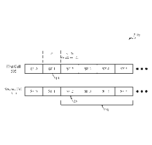
15 [0067] FIG. 5A shows an example of cross-subframe indication of a
CSI reference signal
configuration, in accordance with various aspects of the present disclosure;
[0068] FIG. 5B shows an example of cross-subframe indication of a CSI
reference signal
configuration, in accordance with various aspects of the present disclosure;
[0069] FIG. 6 shows an example of joint and individual grant transmission
and
processing, in accordance with various aspects of the present disclosure;
[0070] FIG. 7 shows a diagram of a limited set of antenna ports for
partial control
channel monitoring in accordance with various aspects of the present
disclosure;
[0071] FIG 8A shows an example of dynamic TTI use, in accordance with
various
aspects of the present disclosure;
[0072] FIG. 8B shows an example of dynamic TTI use, in accordance with
various
aspects of the present disclosure;
[0073] FIG. 9 shows an example of dynamic TTI use, in accordance with
various aspects
of the present disclosure;
CA 02981985 2017-10-05
WO 2016/191091 PCT/US2016/031587
16
[0074] FIG. 10 shows an example of discovery window allocation within a
DMTC
period, in accordance with various aspects of the present disclosure;
[0075] FIG. 11 shows an example discovery window in which DRSs may be
transmitted
in each of a plurality of cells, in accordance with various aspects of the
present disclosure;
[0076] FIGs. 12-19 show block diagrams of wireless devices and components
that
support control flow enhancements for LTE-Unlicensed in accordance with
various aspects
of the present disclosure;
[0077] FIG. 20 illustrates a block diagram of a system including a user
equipment (UE)
that supports control flow enhancements for LTE-Unlicensed in accordance with
various
aspects of the present disclosure;
[0078] FIG. 21 shows a block diagram of a wireless device that supports
control flow
enhancements for LTE-Unlicensed in accordance with various aspects of the
present
disclosure;
[0079] FIG. 22 illustrates a block diagram of a system including a base
station that
supports control flow enhancements for LTE-Unlicensed in accordance with
various aspects
of the present disclosure; and
[0080] FIGs. 23-32 illustrate methods for control flow enhancements for
LTE-Unlicensed
in accordance with various aspects of the present disclosure.
DETAILED DESCRIPTION
[0081] The described features generally relate to improved systems,
methods, or
apparatuses for control flow enhancement for LTE-U operation. The techniques
include
enhancements to control flow processing for floating TTI operation in
unlicensed cells
including ePDCCH processing, aperiodic channel state information (CSI)
reporting, DRX
operation, and extended TTIs at the end of a transmission burst. The described
techniques
also include enhancements for reference signal configuration for unlicensed
cells, processing
of j oint grants for multiple unlicensed cells, ePDCCH processing for partial
subframes, and
multi-channel DRS operation.
CA 02981985 2017-10-05
WO 2016/191091
PCT/US2016/031587
17
[0082] Aspects of the disclosure are initially described in the context
of a wireless
communication system Specific examples are then described for control flow
enhancement
for LTE-U operation. These and other aspects of the disclosure are further
illustrated by and
described with reference to apparatus diagrams, system diagrams, and
flowcharts that relate
to control flow enhancements for Long Term Evolution (LTE)-Unlicensed.
[0083] FIG. 1 illustrates an example of a wireless communications system
100
supporting RRM measurement and reporting for LAA in accordance with various
aspects of
the present disclosure. The wireless communications system 100 includes base
stations 105,
at least one user equipment (UE) 115, and a core network 130. The core network
130 may
provide user authentication, access authorization, tracking, internet protocol
(IP)
connectivity, and other access, routing, or mobility functions. The base
stations 105 interface
with the core network 130 through backhaul links 132 (e.g., Si, etc.). The
base stations 105
may perform radio configuration and scheduling for communication with the UEs
115, or
may operate under the control of a base station controller (not shown). In
various examples,
the base stations 105 may communicate, either directly or indirectly (e.g.,
through core
network 130), with one another over backhaul links 134 (e.g., Xl, etc.), which
may be wired
or wireless communication links.
[0084] The base stations 105 may wirelessly communicate with the IJEs
115 via one or
more base station antennas. Each of the base stations 105 may provide
communication
coverage for a respective geographic coverage area 110 The wireless
communications
system 100 may include base stations 105 of different types (e.g., macro or
small cell base
stations). There may be overlapping geographic coverage areas 110 for
different
technologies. The communication links 125 shown in wireless communications
system 100
may include uplink (UL) transmissions from a UE 115 to a base station 105, or
downlink
(DL) transmissions, from a base station 105 to a UE 115.
[0085] In some examples of the wireless communications system 100, base
stations 105
or UEs 115 may include multiple antennas for employing antenna diversity
schemes to
improve communication quality and reliability between base stations 105 and
UEs 115.
Additionally or alternatively, base stations 105 or UEs 115 may employ
multiple input
multiple output (MIMO) techniques that may take advantage of multi-path
environments to
transmit multiple spatial layers carrying the same or different coded data.
CA 02981985 2017-10-05
WO 2016/191091
PCT/US2016/031587
18
[0086] The wireless communications system 100 may support synchronous or
asynchronous operation. For synchronous operation, the base stations 105 may
have similar
frame timing, and transmissions from different base stations 105 may be
approximately
aligned in time. For asynchronous operation, the base stations 105 may have
different frame
timing, and transmissions from different base stations 105 may not be aligned
in time. The
techniques described herein may be used for either synchronous or asynchronous
operations.
[0087] The communication networks that may accommodate some of the
various
disclosed examples may be packet-based networks that operate according to a
layered
protocol stack and data in the user plane may be based on the IP. A radio link
control (RLC)
layer may perform packet segmentation and reassembly to communicate over
logical
channels. A medium access control (MAC) layer may perform priority handling
and
multiplexing of logical channels into transport channels. The MAC layer may
also use
hybrid automatic repeat request (HARQ) to provide retransmission at the MAC
layer to
improve link efficiency. In the control plane, the radio resource control
(RRC) protocol layer
may provide establishment, configuration, and maintenance of an RRC connection
between a
UE 115 and the base stations 105. The RRC protocol layer may also be used for
core
network 130 support of radio bearers for the user plane data. At the physical
(PHY) layer,
the transport channels may be mapped to physical channels.
[0088] In some examples, the wireless communications system 100 is an
LTE/LTE-
Advanced (LTE-A) network. In LTE/LTE-A networks, the term evolved node B (eNB)
may
be generally used to describe the base stations 105, while the term UE may be
generally used
to describe the UEs 115. A UE 115 may be a cellular phone, a personal digital
assistant
(PDA), a wireless modem, a wireless communication device, a handheld device, a
tablet
computer, a laptop computer, a cordless phone, a wireless local loop (WLL)
station, or the
like. A UE may be able to communicate with various types of base stations and
network
equipment including macro eNBs, small cell eNBs, relay base stations, and the
like. The
wireless communications system 100 may be a heterogeneous LTE/LTE-A network in
which
different types of eNBs provide coverage for various geographical regions. For
example,
each eNB or base station 105 may provide communication coverage for a macro
cell, a small
cell, or other types of cell. The term "cell" can be used to describe a base
station, a carrier or
CA 02981985 2017-10-05
WO 2016/191091
PCT/US2016/031587
19
component carrier associated with a base station, or a coverage area (e.g.,
sector, etc.) of a
carrier or base station, depending on context.
[0089] A HE 115 attempting to access a wireless network may perform an
initial cell
search by detecting a primary synchronization signal (PSS) from a base station
105 The PSS
.. may enable synchronization of slot timing and may indicate a physical layer
identity value.
The UE 115 may then receive a secondary synchronization signal (SSS). The SSS
may
enable radio frame synchronization, and may provide a cell identity value,
which may be
combined with the physical layer identity value to identify the cell. The SSS
may also enable
detection of a duplexing mode and a cyclic prefix length. Both the PSS and the
SSS may be
located in the central 62 and 72 subcarriers of a carrier, respectively. In
some cases, PSS,
SSS, and other signals such as cell specific reference signals (CRS) for
channel estimation
may be configured according to a reduced periodicity transmission schedule to
conserve
energy or reduce inter-cell interference. Such a configuration may be known as
a discovery
reference signal (DRS) configuration.
[0090] A UE 115 may enter an idle mode and use discontinuous reception
(DRX) to
reduce power consumption in the idle mode. In DRX operation, the UE is
configured to
periodically wake up to receive paging messages according to a DRX cycle,
which may be a
default DRX cycle for the cell or a UE-specific DRX cycle. The UE determines
paging
frames for which it will wake up to check for paging messages according to the
DRX cycle
and a UE-specific identifier determined from the unique international mobile
subscriber
identity (IMSI) assigned to the UE 115. The UE 115 checks specific paging
occasions,
which are subframes within the paging frame deteimined according to the DRX
cycle and the
UE-specific identifier. If the serving gateway (S-GW) receives data for the UE
115, it may
notify the mobility management entity (114ME), which may send a paging message
to every
base station 105 within an area known as a tracking area. Each base station
105 within the
tracking area may send a paging message to the UE 115 during a paging
occasion. Thus the
UE may remain in idle without updating the MME until it leaves the tracking
area.
[0091] In some cases, a UE 115 may be configured in connected mode DRX.
In
connected mode DRX, a DRX cycle consists of an "On Duration" when the UE 115
may
monitor for control information (e.g., on physical downlink control channel
(PDCCH)) and a
"DRX period" when the UE115 may power down radio components). In some cases, a
UE
CA 02981985 2017-10-05
WO 2016/191091 PCT/US2016/031587
115 may be configured with a short DRX cycle and a long DRX cycle In some
cases, a UE
115 may enter a long DRX cycle if it is inactive for one or more short DRX
cycles. The
transition between the short DRX cycle, the long DRX cycle, and continuous
reception may
be controlled by an internal timer or by messaging from a base station 105. A
UE 115 may
5 receive scheduling messages on PDCCH during the On Duration. While
monitoring PDCCH
for a scheduling message, the UE 115 may initiate a "DRX Inactivity Timer". If
a scheduling
message is successfully received, the UE 115 may prepare to receive data and
the DRX
Inactivity Timer may be reset. When the DRX Inactivity Timer expires without
receiving a
scheduling message, the UE 115 may move into a short DRX cycle and may start a
"DRX
10 Short Cycle Timer". When the DRX Short Cycle Timer expires, the UE 115
may resume a
long DRX cycle.
[0092] A base station 105 may insert periodic pilot symbols such as cell-
specific
reference signals (CRS) to aid UEs 115 in channel estimation and coherent
demodulation.
CRS from different cells may have different sequences and/or be transmitted on
different
15 transmission resources based on a physical cell identity of the
transmitting cell, which may be
one of 504 different cell identities. CRS may be modulated using quadrature
phase shift
keying (QPSK) and power boosted (e.g., transmitted at 6dB higher than the
surrounding data
elements) to make them resilient to noise and interference. CRS may be
embedded in 4 to 16
resource elements in each resource block based on the number of antenna ports
or layers (up
20 to 4) of the receiving UEs 115. In addition to CRS, which may be
utilized by all UEs 115 in
the coverage area 110 of the base station 105, demodulation reference signal
(DMRS), also
called UE-specific reference signals (UE-RS) may be directed toward specific
UEs 115 and
may be transmitted only on resource blocks assigned to those UEs 115. DMRS may
include
signals on 6 resource elements in each resource block in which they are
transmitted. The DM-
RS for different antenna ports may each utilize the same 6 resource elements,
and may be
distinguished using different orthogonal cover codes (e.g., masking each
signal with a
different combination of 1 or -1 in different resource elements). In some
cases, two sets of
DMRS may be transmitted in adjoining resource elements. In some cases,
additional
reference signals known as CSI reference signals (CSI-RS) may be included to
aid in
determining CSI parameters for reporting. On the UL, a UE 115 may transmit a
combination
of periodic sounding reference signal (SRS) and UL DMRS for link adaptation
and
demodulation, respectively.
CA 02981985 2017-10-05
WO 2016/191091
PCT/US2016/031587
21
[0093] A base station 105 may gather channel condition information from
a UE 115 in
order to efficiently configure and schedule the channel. This information may
be sent from
the UE 115 in the form of a CSI report A CSI report may contain a rank
indicator (RI)
requesting a number of layers to be used for DL transmissions (e.g., based on
the antenna
ports of the UE 115), a precoding matrix indicator (PMI) indicating a
preference for which
precoder matrix should be used (based on the number of layers), or a channel
quality
indicator (CQI) representing the highest modulation and coding scheme (MCS)
that may be
used. CQI may be calculated by a UE 115 after receiving predetermined pilot
symbols such
as CRS or CSI-RS. RI and PMI may be excluded if the UE 115 does not support
spatial
multiplexing (or is not in support spatial mode). The types of information
included in the
report determines a reporting type. CSI reports may be periodic or aperiodic.
That is, a base
station 105 may configure a UE 115 to send periodic reports at regular
intervals, and may
also request additional reports as needed. Aperiodic reports may include
wideband reports
indicating the channel quality across an entire cell bandwidth, UE selected
reports indicating
a subset of the best sub-bands, or configured reports in which the sub-bands
reported are
selected by the base station 105.
[0094] In some cases, a wireless communications network 100 may include
small cells
whose coverage areas 110 may overlap the coverage area 110 of one or more
macro base
stations 105 In some cases, small cells may be added in areas with high user
demand or in
areas not sufficiently covered by a macro base station 105. For example, a
small cell may be
located in a shopping center, or in an area where signal transmissions are
blocked by terrain
or buildings. In some cases, small cells may improve network performance by
allowing
macro base stations 105 to offload traffic when load is high. A network that
includes both
large and small cells may be known as a heterogeneous network. A heterogeneous
network
may also include Home evolved node B (HeNB s) which may provide service to a
restricted
group known as a closed subscriber group (CSG). For example, an office
building may
contain small cells for use only by the occupants of the building. In some
cases,
heterogeneous networks may involve more complex network planning and
interference
mitigation techniques than homogenous networks.
[0095] Wireless communications system 100 may support operation on multiple
cells or
carriers, a feature which may be referred to as carrier aggregation (CA) or
multi-carrier
CA 02981985 2017-10-05
WO 2016/191091 PCT/US2016/031587
22
operation. A carrier may also be referred to as a component carrier (CC), a
layer, a channel,
etc. The term "component carrier" may refer to each of the multiple carriers
utilized by a UE
in CA operation, and may be distinct from other portions of system bandwidth.
For instance,
a component carrier may be a relatively narrow-bandwidth carrier susceptible
of being
.. utilized independently or in combination with other component carriers.
Each component
carrier may provide the same capabilities as a single carrier based on release
8 or release 9 of
the Long Term Evolution (LTE) standard. Multiple component carriers may be
aggregated or
utilized concurrently to provide some UEs 115 with greater bandwidth and
higher data rates.
Thus, individual component carriers may be backwards compatible with legacy
UEs 115
(e.g., UEs 115 implementing LTE release 8 or release 9); while other UEs 115
(e.g., UEs 115
implementing post-release 8/9 LTE versions), may be configured with multiple
component
carriers in a multi-carrier mode. A carrier used for downlink (DL) may be
referred to as a DL
CC, and a carrier used for uplink (UL) may be referred to as an UL CC. A UE
115 may be
configured with multiple DL CCs and one or more UL CCs for carrier
aggregation. Each
carrier may be used to transmit control information (e.g., reference signals,
control channels,
etc.), overhead information, data, etc. A UE 115 may communicate with a single
base station
105 utilizing multiple carriers, and may also communicate with multiple base
stations
simultaneously on different carriers. A UE 115 may be configured with multiple
downlink
CCs and one or more uplink CCs for carrier aggregation. Carrier aggregation
may be used
with both FDD and TDD component carriers.
[0096] Each cell of a base station 105 includes a CC that may be a DL CC
or a TDD CC.
The cell may include an UL CC in FDD operation. The coverage area 110 of each
serving
cell for a base station 105 may be different (e.g., CCs on different frequency
bands may
experience different path loss). In some examples, one carrier is designated
as the primary
carrier, or primary component carrier (PCC), for a UE 115, which may be served
by a
primary cell (PCell). Primary cells may be semi-statically configured by
higher layers (e.g.,
radio resource control (RRC), etc.) on a per-UE basis. Certain uplink control
information
(UCI), (e.g., acknowledgement (ACK)/NACK, channel quality indicator (CQI), and
scheduling information transmitted on physical uplink control channel
(PUCCH)), are carried
by the primary cell. Additional carriers may be designated as secondary
carriers, or
secondary component carriers (SCC), which may be served by secondary cells
(SCells).
Secondary cells may likewise be semi-statically configured on a per-UE basis.
In some
CA 02981985 2017-10-05
WO 2016/191091
PCT/US2016/031587
23
cases, secondary cells may not include or be configured to transmit the same
control
info, __________________________________________________________________
illation as the primary cell In other cases, one or more secondary cell
(SCells) may be
designated to carry physical uplink control channel (PUCCH), and the SCells
may be
organized into PUCCH groups based on which CC is used to carry the associated
UL control
information. Some wireless networks may utilize enhanced CA operations based
on a large
number of carriers (e.g., between 5 and 32 carriers), operation in unlicensed
spectrum, or use
of enhanced CCs.
[0097] In some cases, configured SCells are activated and deactivated for
individual UEs
115 by a configuring cell using a primary carrier (e.g., PCell, etc.). For
example, activation
and deactivation commands for configured SCells may be carried in MAC
signaling. When
an SCell is deactivated, the UE 115 does not need to monitor for control
information for the
SCell. The UE 115 also does not need to receive the corresponding downlink CC,
cannot
transmit in the corresponding uplink CC, nor is it required to perform channel
quality
information (CQI) measurements. Upon deactivation of an SCell, the UE may also
flush all
HARQ buffers associated with the SCell. Conversely, when an SCell is active,
the UE 115
receives control information and/or data transmissions for the SCell, and is
expected to be
able to perform CQI measurements The activation/deactivation mechanism is
based on the
combination of a MAC control element and deactivation timers The MAC control
element
carries a bitmap for the individual activation and deactivation of SCells such
that SCells can
be activated and deactivated individually, and a single
activation/deactivation command can
activate/deactivate a subset of the SCells. One deactivation timer is
maintained per SCell but
one common value is configured per UE by RRC.
[0098] In some cases, a UE 115 or base station 105 may operate in a
shared frequency
spectrum band. As used herein, the term "shared frequency spectrum band" means
one or
.. more bands of unlicensed or shared spectrum subject to contention
resolution procedures for
access to shared frequency resources of the band. Cells operating in shared
frequency
spectrum bands may be configured to be used in a standalone mode of operation
(e.g., used as
a primary carrier for one or more UEs), or in a license assisted access (LAA)
mode. Other
devices may also be operating in the unlicensed or shared frequency spectrum.
By way of
example, FIG. 1 shows a network comprised of a Wi-Fi access point (AP) 150 in
communication with Wi-Fi stations (STAs) 155 via communication links 165 in
unlicensed
CA 02981985 2017-10-05
WO 2016/191091 PCT/US2016/031587
24
frequency spectrum. When communicating via an unlicensed cell, devices use a
listen-
before-talk (LBT) procedure (e.g., clear channel assessment (CCA), etc.) prior
to
communicating in order to determine whether the channel is available. A CCA
may include
an energy detection procedure to determine whether there are any other active
transmissions.
For example, the device may infer that detected energy (e.g., RSSI) over a
certain level
indicates that a channel is occupied. Specifically, signal power that is
concentrated in a
certain bandwidth and exceeds a predetermined noise floor may indicate another
wireless
transmitter is currently transmitting over the channel. The LBT procedure may
also include
detection of specific sequences that indicate use of the channel. For example,
another device
may transmit a specific preamble prior to transmitting a data sequence.
[0099] In some examples, UEs 115 may be configured for CA using a PCell
in dedicated
spectrum and one or more SCells in a shared frequency spectrum band. UEs 115
or eNBs
105 using LAA cells may utilize LBT procedures for transmissions in the shared
frequency
spectrum band. These devices may perform an LBT procedure prior to
communicating in
order to determine whether the channel is available. The LBT procedure may
include energy
detection and preamble detection procedures to determine whether there are any
other active
transmissions.
[0100] FIG. 2 shows a wireless communication system 200 in which LTE/LTE-A may
be
deployed under different scenarios using a shared frequency spectrum band, in
accordance
with various aspects of the present disclosure. More specifically, FIG. 2
illustrates examples
of a supplemental downlink mode (e.g., LAA), a carrier aggregation (CA) mode,
and a
standalone (SA) mode in which LTE/LTE-A is deployed using a shared frequency
spectrum
band. The wireless communication system 200 may be an example of portions of
the
wireless communication system 100 described with reference to FIG. 1.
Moreover, a first
eNB 105-a and a second eNB 105-b may be examples of aspects of one or more of
the eNBs
105 described with reference to FIG. 1, while a first UE 115-a, a second UE
115-b, a third
UE 115-c, and a fourth UE 115-d may be examples of aspects of one or more of
the UEs 115
described with reference to FIG. 1.
[0101] In the example of a supplemental downlink mode (e.g., LAA) in the
wireless
communication system 200, the first eNB 105-a may transmit OFDMA waveforms to
the first
UE 115-a using a downlink channel 220. The downlink channel 220 may be
associated with
CA 02981985 2017-10-05
WO 2016/191091 PCT/US2016/031587
a frequency Fl in a shared frequency spectrum band The first eNB 105-a may
transmit
OFDMA waveforms to the first UE 115-a using a first bidirectional link 225 and
may receive
SC-FDMA waveforms from the first UE 115-a using the first bidirectional link
225. The first
bidirectional link 225 may be associated with a frequency F4 (or multiple
frequencies) in a
5 dedicated frequency spectrum band. The downlink channel 220 in the shared
frequency
spectrum band and the first bidirectional link 225 in the dedicated frequency
spectrum band
may operate contemporaneously. The downlink channel 220 may provide a downlink
capacity offload for the first eNB 105-a. In some examples, the downlink
channel 220 may
be used for unicast services (e.g., addressed to one UE) or for multicast
services (e.g.,
10 addressed to several UEs). This scenario may occur with any service
provider (e.g., mobile
network operator (MNO), etc.) that has deployed capacity in a dedicated
frequency spectrum
with the capability of off-loading to the shared frequency spectrum band.
[0102] In one example of a carrier aggregation mode in the wireless
communication
system 200, the first eNB 105-a may transmit OFDMA waveforms to the second UE
115-b
15 using a second bidirectional link 230 and may receive OFDMA waveforms,
SC-FDMA
waveforms, or resource block interleaved FDMA waveforms from the second UE 115-
b
using the second bidirectional link 230. The second bidirectional link 230 may
be associated
with the frequency Fl in the shared frequency spectrum band. The first eNB 105-
a may also
transmit OFDMA waveforms to the second UE 115-b using a third bidirectional
link 235 and
20 may receive SC-FDMA waveforms from the second UE 115-b using the third
bidirectional
link 235. The third bidirectional link 235 may be associated with a frequency
F2 in a
dedicated frequency spectrum band. The second bidirectional link 230 may
provide a
downlink and uplink capacity offload for the first eNB 105-a. Like the
supplemental
downlink mode described above, this scenario may occur with any service
provider (e.g.,
25 MNO) that has deployed capacity in a dedicated frequency spectrum with
the capability of
off-loading to the shared frequency spectrum band.
[0103] In another example of a carrier aggregation mode in the wireless
communication
system 200, the first eNB 105-a may transmit OFDMA waveforms to the third UE
115-c
using a fourth bidirectional link 240 and may receive OFDMA waveforms, SC-FDMA
waveforms, or resource block interleaved waveforms from the third UE 115-c
using the
fourth bidirectional link 240. The fourth bidirectional link 240 may be
associated with a
CA 02981985 2017-10-05
WO 2016/191091
PCT/US2016/031587
26
frequency F3 in the shared frequency spectrum band. The first eNB 105-a may
also transmit
OFDMA waveforms to the third UE 115-c using a fifth bidirectional link 245 and
may
receive SC-FDMA waveforms from the third UE 115-c using the fifth
bidirectional link 245.
The fifth bidirectional link 245 may be associated with the frequency F2 in
the dedicated
frequency spectrum band. The fourth bidirectional link 240 may provide a
downlink and
uplink capacity offload for the first eNB 105-a. This example and those
provided above are
presented for illustrative purposes and there may be other similar modes of
operation or
deployment scenarios that combine LTE/LTE-A in a dedicated frequency spectrum
band and
use a shared frequency spectrum band for capacity offload.
[0104] As described above, one type of service provider that may benefit from
the capacity
offload offered by using LTE/LTE-A in a shared frequency spectrum band is a
traditional
MNO having access rights to an LTE/LTE-A dedicated frequency spectrum band.
For these
service providers, an operational example may include a bootstrapped mode
(e.g.,
supplemental downlink, carrier aggregation) that uses the LTE/L1E-A primary
component
carrier (PCC) on the dedicated frequency spectrum band and at least one
secondary
component carrier (SCC) on the shared frequency spectrum band.
[0105] In the carrier aggregation mode, data and control may, for example, be
communicated in the dedicated frequency spectrum band (e.g., via first
bidirectional link 225,
third bidirectional link 235, and fifth bidirectional link 245) while data
may, for example, be
communicated in the shared frequency spectrum band (e.g., via second
bidirectional link 230
and fourth bidirectional link 240). The carrier aggregation mechanisms
supported when
using a shared frequency spectrum band may fall under a hybrid frequency
division
duplexing-time division duplexing (FDD-TDD) carrier aggregation or a TDD-1DD
carrier
aggregation with different symmetry across component carriers.
[0106] In one example of a standalone mode in the wireless communication
system 200,
the second eNB 105-b may transmit OFDMA waveforms to the fourth UE 115-d using
a
bidirectional link 250 and may receive OFDMA waveforms, SC-FDMA waveforms, or
resource block interleaved FDMA waveforms from the fourth UE 115-d using the
bidirectional link 250. The bidirectional link 250 may be associated with the
frequency F3 in
the shared frequency spectrum band. The standalone mode may be used in non-
traditional
wireless access scenarios, such as in-stadium access (e.g., unicast,
multicast). An example of
CA 02981985 2017-10-05
WO 2016/191091
PCT/US2016/031587
27
a type of service provider for this mode of operation may be a stadium owner,
cable
company, event host, hotel, enterprise, or large corporation that does not
have access to a
dedicated frequency spectrum band.
[0107] In some examples, a transmitting apparatus such as one of the eNBs 105
described
with reference to FIG. 1 or 2, or one of the UEs 115 described with reference
to FIG. 1 or 2,
may use a gating interval to gain access to a channel of a shared frequency
spectrum band
(e.g., to a physical channel of the shared frequency spectrum band). In some
examples, the
gating interval may be periodic. For example, the periodic gating interval may
be
synchronized with at least one boundary of an LTE/LTE-A radio interval. The
gating
interval may define the application of a contention-based protocol, such as an
LBT protocol
based on the LBT protocol specified in European Telecommunications Standards
Institute
(ETSI) (EN 301 893). When using a gating interval that defines the application
of an LBT
protocol, the gating interval may indicate when a transmitting apparatus needs
to perform a
contention procedure (e.g., an LBT procedure) such as a CCA procedure. The
outcome of
the CCA procedure may indicate to the transmitting apparatus whether a channel
of a shared
frequency spectrum band is available or in use for the gating interval (also
referred to as an
LBT radio frame). When a CCA procedure indicates that the channel is available
for a
corresponding LBT radio frame (e.g., "clear" for use), the transmitting
apparatus may reserve
or use the channel of the shared frequency spectrum band during part or all of
the LBT radio
frame. When the CCA procedure indicates that the channel is not available
(e.g., that the
channel is in use or reserved by another transmitting apparatus), the
transmitting apparatus
may be prevented from using the channel during the LBT radio frame.
[0108] FIG. 3A shows a timeline 300 of communications in an uplink, in
accordance with
various aspects of the present disclosure. The timeline 300 shows a
transmission opportunity
305 including a downlink transmission (Tx) period 310 followed by an uplink
transmission
(Tx) period 315. In some examples, the downlink transmission period 310 may be
subdivided into a plurality of downlink TTIs (e.g., downlink (D) subframes),
and the uplink
transmission period 315 may be subdivided into a plurality of uplink TTIs
(e.g., uplink (U)
subframes).
[0109] In some examples, one or more of the downlink TTIs in the downlink
transmission
period 310 may carry uplink grants for one or more uplink TTIs in the uplink
transmission
CA 02981985 2017-10-05
WO 2016/191091 PCT/US2016/031587
28
period 315 (e.g., for same-carrier scheduling, or self-scheduling of uplink
transmissions). In
other examples, one or more uplink grants for one or more uplink TTIs in the
uplink
transmission period 315 may be transmitted on a different CC than the CC shown
in FIG 3A
(e.g., for cross-carrier scheduling).
[0110] When multiple TTIs are scheduled for the uplink transmission period
315, DCI
(e.g., a DCI Format 0) for the multiple TTIs may include parameters such as.
resource block
(RB) allocation, modulation and coding scheme (MCS) and redundancy value (RV),
new data
indicator (NDI), transmit power control (TPC) command, cell-specific
demodulation
reference signal (CS-DMRS), uplink (UL) index, downlink assignment index
(DAI), channel
state information (CSI) request, sounding reference signal (SRS) request,
resource allocation
type, or a combination thereof. In LTE/LTE-A networks, TDD Format 0 allows two
separate
uplink grants to be carried to a single UE in a downlink TTI in a dedicated
radio frequency
spectrum band The application of each uplink grant may be determined by an UL
index
associated with the uplink grant, and may influence power control, aperiodic
CSI reporting,
and PUSCH transmission. Similar functionality may be provided for an uplink
grant
applicable to an uplink transmission in a shared radio frequency spectrum
band.
[0111] Assuming no cross-transmission opportunity scheduling or cross-carrier
scheduling,
multiple uplink grants for a multiple-TTI uplink transmission in a shared
radio frequency
spectrum band during the uplink transmission period 315 (which may be carried
within a
single downlink TTI of the downlink transmission period 310) may each include
DCI fields
such as: a UL index field, a HARQ index field, a reference signal and PUSCH
multiplexing
indicator field (e.g., a SRS/PUSCH multiplexing indicator field), a resource
reuse indicator
field (e.g., a PUCCH/PRACH resource reuse indicator field), LBT parameters, or
a
combination thereof. A UL index may indicate to a UE which uplink TTI (e.g.,
uplink
subframe) in the transmission opportunity 305 (also referred to as a current
transmission
burst) carries a PUSCH transmission. The UL index may be referenced to an end
of the
downlink TTI carrying the uplink grant that includes the UL index. LBT
parameters may
indicate to a UE whether to puncture a first symbol of an uplink TTI to
perform a shortened
LBT procedure (e.g., a 25 [Is LBT procedure), or whether to perform a full-
length LBT
procedure (e.g., a category (CAT) 4 LBT procedure). When indicating to perform
a CAT 4
LBT procedure, the LBT parameters may indicate one or more of a LBT priority
class or a
CA 02981985 2017-10-05
WO 2016/191091 PCT/US2016/031587
29
contention window size. In some examples, the loss of contention to access a
shared radio
frequency spectrum band during a TTI of a multi-TTI uplink transmission (e.g.,
by a UE
performing a CAT 4 LBT procedure) may cause the UE to carryover the CAT 4 LBT
procedure parameters to a next TTI of the multi-TTI uplink transmission.
[0112] FIG. 3B shows a timeline 320 of communications in an uplink, in
accordance with
various aspects of the present disclosure. The timeline 320 shows a first
transmission
opportunity 325 followed by a second transmission opportunity 340. The first
transmission
opportunity 325 may include a first downlink Tx period 330 followed by a first
uplink Tx
period 335. The second transmission opportunity 340 may include a second
downlink
transmission (Tx) period 345 followed by a second uplink Tx period 350. In
some examples,
one or both of the downlink transmission periods (e.g., the first downlink
transmission period
330 or the second downlink transmission period 345) may be subdivided into a
plurality of
downlink TTIs (e.g., D subframes), and one or both of the uplink transmission
periods (e.g.,
the first uplink transmission period 335 or the second uplink transmission
period 350) may be
subdivided into a plurality of uplink TTIs (e.g., U subframes).
[0113] In some examples, one or more of the downlink TTIs in the first
downlink Tx
period 330 may carry uplink grants for one or more uplink TTIs in the second
uplink Tx
period 335 (e.g., cross-transmission opportunity scheduling of uplink
transmissions).
[0114] Assuming cross-transmission opportunity scheduling is used to schedule
uplink
transmissions in the second uplink transmission period 350, and assuming that
the second
downlink transmission period 345 precedes the second uplink transmission
period 350,
multiple uplink grants for a multiple-TTI uplink transmission in a shared
radio frequency
spectrum band during the second uplink transmission period 350 (which may be
carried
within a downlink TTI of the first downlink Tx period 330) may each include
DCI fields such
as: a UL index field, a HARQ index field, a reference signal and PUSCH
multiplexing
indicator field (e.g., a SRS/PUSCH multiplexing indicator field), a resource
reuse indicator
field (e.g., a PUCCH/PRACH resource reuse indicator field), LBT parameters, or
a
combination thereof. In addition, each uplink grant may include DCI fields
such as: a current
transmission burst index field, a target transmission burst index field, or a
PUSCH
.. transmission skipping strategy field. A current transmission burst index
may indicate to a UE
a first transmission burst (e.g., the first transmission opportunity 325) in
which an uplink
CA 02981985 2017-10-05
WO 2016/191091 PCT/US2016/031587
grant is received, and a target transmission burst index may indicate to the
UE a second
transmission burst (e.g., the second transmission opportunity 340) to which
the uplink grant
applies. In some examples, a base station may broadcast the current
transmission burst index
to a plurality of UEs, in DCI on a common PDCCH. A UL index may identify an
uplink TTI
5 .. of the second transmission burst (e.g., the second transmission
opportunity 340) in which a
PUSCH transmission begins. A PUSCH transmission skipping strategy may
indicate, to a
UE, whether to skip at least a temporally first PUSCH transmission, or at
least a temporally
last PUSCH transmission, when a LBT procedure for at least a first TTI of a
multiple-TTI
transmission is not successful.
10 [0115] In some examples, a UE that receives at least one uplink grant
for at least one TTI
of a multiple-TTI uplink transmission in a shared radio frequency spectrum
band may
perform a LBT procedure to contend for access to the shared radio frequency
spectrum band
for a TTI of the multiple-TTI uplink transmission. Upon losing contention for
access to the
shared radio frequency spectrum band for the TTI, the UE may trigger an uplink
transmission
15 carryover strategy. The uplink transmission carryover strategy may
indicate to the UE to
carryover or not carryover, to a next TTI of the multiple-TTI uplink
transmission, a parameter
associated with the TTI for which contention for access to the shared radio
frequency
spectrum band is lost. In some examples, the parameter may include a CST
transmission
parameter, or a SRS transmission parameter, or a TPC command, or a combination
thereof.
20 In some examples, a carried over TPC command may be applied cumulatively
to a TTI.
[0116] In some examples, a UE that receives at least one uplink grant for at
least one TTI
of a multiple-TTI uplink transmission in a shared radio frequency spectrum
band may
perform a LBT procedure to contend for access to the shared radio frequency
spectrum band
for a TTI of the multiple-TTI uplink transmission. Upon winning contention for
access to the
25 shared radio frequency spectrum band for the TTI, the UE may transmit
data associated with
a LBT priority class (e.g., best effort data, video data, etc.) indicated in
an uplink grant for the
TTI. Upon running out of data associated with the LBT priority class, the UE
may or may
not transmit junk data for the remainder of the TTI.
[0117] In some examples, a UE that receives at least one uplink grant for at
least one TTI
30 of a multiple-TTI uplink transmission in a shared radio frequency
spectrum band may be
CA 02981985 2017-10-05
WO 2016/191091 PCT/US2016/031587
31
triggered to transmit a SRS without a PUSCH transmission during a TTI, by
disabling all of
the transport blocks (TBs) within the TTI.
[0118] FIG. 3C shows a timeline 360 of communications in an uplink of a shared
radio
frequency spectrum band, and the performance of a LBT procedure 380, followed
by a
transmission of a channel reservation signal 385, in accordance with various
aspects of the
present disclosure. The timeline 360 shows one TTI 365 (e.g., one uplink (U)
subframe) of
an uplink transmission period (e.g., one TTI of the uplink transmission period
315 described
with reference to FIG. 3A or the first uplink transmission period 335 or
second uplink
transmission period 350 described with reference to FIG. 3B). The TTI 365
includes a
plurality of symbol periods (e.g., 14 symbol periods numbered 0-13) spanning
two slots (e.g.,
a Slot 0 370 and a Slot 1 375).
[0119] A UE may perform a LBT procedure 380 for the TTI 365. In some examples,
the
LBT procedure 380 may be performed during a temporally first symbol period
(e.g., Symbol
Period 0) of the TTI 365. In some examples (not shown), the LBT procedure 380
may be
synced to an end of the first symbol period, and upon winning contention for
access to the
shared radio frequency spectrum band, the UE may immediately begin an uplink
transmission
(e.g., a PUSCH transmission, or a PUCCH transmission, or a PRACH transmission,
or a SRS
transmission, or a combination thereof) in a temporally second symbol period
(e.g., Symbol
Period 1) of the TTI 365 In other examples (shown), the LBT procedure 380 may
be synced
to a beginning of the first symbol period and performed during a first portion
of the first
symbol period), and upon winning contention for access to the shared radio
frequency
spectrum band, the HE may transmit a channel reservation signal (RES 385)
during a second
portion of the first symbol period. The channel reservation signal may be
transmitted to
reserve the shared radio frequency spectrum band between a time contention for
access to the
shared radio frequency spectrum band is won and a time an uplink transmission
is scheduled
to begin.
[0120] In some examples, the HE may select one of a plurality of different
channel
reservation signals to transmit during the second portion of the first symbol
period (e.g., as
RES 385). When the HE is scheduled to transmit a SRS before a PUSCH during the
TTI
365, the selected channel reservation signal may include a SRS waveform. When
the HE is
scheduled to transmit a PUSCH but not a SRS during the TTI 365, and when a
junk SRS
CA 02981985 2017-10-05
WO 2016/191091 PCT/US2016/031587
32
interface is active during the first symbol period of the TTI, the selected
channel reservation
signal may include a junk SRS waveform. When a network access device that
transmits an
uplink grant for the TTI 365 does not indicate a selection methodology for
selecting the
channel reservation signal, the selected channel reservation signal may
include a Wi-Fi
channel reservation signal (e.g., a clear to send to self (CTS2S)).
Alternatively, when the
network access device that transmits the uplink grant for the TTI 365 does not
indicate a
selection methodology for selecting the channel reservation signal, the UE may
select any
form a channel reservation signal.
[0121] FIG. 4A shows a wireless communication system 400 in which LTE/LTE-A
may
be deployed in a carrier aggregation mode, in accordance with various aspects
of the present
disclosure. The wireless communication system 400 may be an example of
portions of the
wireless communication system 100 or 200 described with reference to FIG. 1 or
2.
Moreover, an eNB 105-c may be an example of aspects of one or more of the eNBs
105
described with reference to FIG. 1 or 2, while a UE 115-e may be an examples
of aspects of
one or more of the UEs 115 described with reference to FIG. 1 or 2.
[0122] When communicating in a carrier aggregation mode using LTE/LTE-A
communications, the UE 115-e may communicate with the eNB 105-c using multiple
CCs.
One of the CCs may be designated as a primary CC, and the remaining CCs may be
designated as secondary CCs. Each CC may be for use as a DL CC and/or a UL CC.
By way
of example, FIG. 4A illustrates communication between the UE 115-e and the eNB
105-c
over five CCs, including a first CC 420, a second CC 425, a third CC 430, a
fourth CC 435,
and a fifth CC 440. Each of the first CC 420, the second CC 425, the third CC
430, the
fourth CC 435, and the fifth CC 440 may operate in a dedicated frequency
spectrum band or a
shared frequency spectrum band, depending on how the CC is allocated or
configured.
[0123] When the UE 115-e is configured for operation in a supplemental
downlink mode
of operation using a shared frequency spectrum band, as described with
reference to FIG. 2,
and when the UE 115 is operating in a carrier aggregation mode, one or more of
the first CC
420, the second CC 425, the third CC 430, the fourth CC 435, or the fifth CC
440 may
operate as a UL CC or a DL CC in the dedicated frequency spectrum band, and
one or more
of the first CC 420, the second CC 425, the third CC 430, the fourth CC 435,
or the fifth CC
440 may operate as a DL CC in the shared frequency spectrum band.
CA 02981985 2017-10-05
WO 2016/191091
PCT/US2016/031587
33
[0124] When the UE 115-e is configured for operation in a carrier aggregation
mode of
operation using the shared frequency spectrum band, as described with
reference to FIG. 2,
one or more of the first CC 420, the second CC 425, the third CC 430, the
fourth CC 435, or
the fifth CC 440 may operate as a UL CC or a DL CC in the dedicated frequency
spectrum
band, and one or more of the first CC 420, the second CC 425, the third CC
430, the fourth
CC 435, or the fifth CC 440 may operate as a DL CC or a UL CC in the shared
frequency
spectrum band. In some examples, all of the DL CCs may operate in the
dedicated frequency
spectrum band, or all of the UL CCs may operate in the shared frequency
spectrum band, but
not all of the DL CCs and all of the UL CCs may operate in the shared
frequency spectrum
band (e.g., at least one DL CC or at least UL CC operates in the dedicated
frequency
spectrum band).
[0125] When the UE 115-e is configured for operation in a standalone mode of
operation
using the shared frequency spectrum band, as described with reference to FIG.
2, and when
the UE 115 is operating in a carrier aggregation mode, each of the first CC
420, the second
CC 425, the third CC 430, the fourth CC 435, and the fifth CC 440 may operate
in the shared
frequency spectrum band.
[0126] FIG. 4B shows a wireless communication system 450 in which LTE/LTE-A
may
be deployed in a multi-connectivity scenario (e.g., a coordinated multipoint
(CoMP)
scenario), in accordance with various aspects of the present disclosure. The
wireless
communication system 450 may be an example of portions of the wireless
communication
system 100 or 200 described with reference to FIG. 1 or 2. Moreover, a first
eNB 105-d and
a second eNB 105-e may be examples of aspects of one or more of the eNBs 105
described
with reference to FIG. 1, 2, or 4A, while a UE 115-f may be an example of
aspects of one or
more of the UEs 115 described with reference to FIG. 1, 2, or 4A.
[0127] When communicating in a multi-connectivity mode using LTE/LTE-A
communications, the UE 115-f may communicate with multiple eNBs, such as the
first eNB
105-d and the second eNB 105-e, using multiple CCs. One of the CCs may be
designated as
a primary CC, and the remaining CCs may be designated as secondary CCs. Each
CC may
be configured as a DL CC, a UL CC, or a cell (e.g., a CC that may be
configured for use as a
DL CC and/or a UL CC). By way of example, FIG. 4B illustrates communication
between
the UE 115-f and the eNBs 105-d, 105-e over three CCs, including a first CC
455, a second
CA 02981985 2017-10-05
WO 2016/191091
PCT/US2016/031587
34
CC 460 and a third CC 465. In some examples, the first CC 455 and the second
CC 460 (in
communication with the first eNB 105-d) may be configured as a primary group
of CCs 470
in a multi-connectivity operation, and the third CC 465 (in communication with
the second
eNB 105-e) may be configured as a secondary group of CCs 475 (e.g., in this
example, a
group of one) in the multi-connectivity operation. The first CC 455, the
second CC 460, and
the third CC 465 may be configured for various modes of operation using a
dedicated
frequency spectrum band or a shared frequency spectrum band, similarly to how
component
carriers may be used in a carrier aggregation mode of operation, as described,
for example,
with reference to FIG. 4A.
[0128] For LTE/LTE-A operation, a UE performs channel measurements according
to a
CSI reference signal configuration, which specifies the locations of reference
signals in each
subframe. The CSI reference signal configuration may be used for purposes such
as rate
matching or channel measurement. When a CSI reference signal is transmitted on
a cell in a
dedicated frequency spectrum band, transmission of the CSI reference signal is
periodic, and
the periodicity of the transmission is based on a configuration. When a CSI
reference signal
(e.g., an eCRS, a CSI-RS, a ZP CSI-RS, an IMR signal, a PSS, or an SSS) is
transmitted on a
cell in a shared frequency spectrum band, transmission of the CSI reference
signal may be
periodic or aperiodic. In addition, because transmissions may be subject to
LBT procedures,
transmission of a CSI reference signal on a cell in a shared frequency
spectrum band may be
opportunistic. Thus, a CSI reference signal configuration may indicate that a
CSI reference
signal is to be transmitted, but an eNB may not transmit the CSI reference
signal because the
eNB does not win contention for access to the shared frequency spectrum band
(i.e., the CSI
reference signal configuration may indicate that a CSI reference signal is to
be transmitted in
a DL subframe, but the DL subframe may not be a valid DL subframe). Ambiguity
therefore
exists regarding the configuration of CSI reference signals (e.g., the
presence and location of
CSI reference signals) in DL subframes transmitted on a cell in a shared
frequency spectrum
band.
[0129] According to some aspects, ambiguity regarding the configuration of CSI
reference
signals (e.g., in DL subframes transmitted on a cell in a shared frequency
spectrum band) is
addressed by designating a first N subframes of a DL burst as subframes
carrying CSI
reference signals. A configuration designating the N subframes, and the CSI
reference signal
CA 02981985 2017-10-05
WO 2016/191091
PCT/US2016/031587
configuration(s), may be provided to a UE on a static or semi-static basis. In
some examples,
the configuration may indicate a set of CSI reference signals, ports, etc.,
that are common to
each of the N subframes. In other examples, the configuration may indicate a
set of CSI
reference signals, ports, etc., for each of the N subframes (e.g., the set of
CSI reference
5 signals, ports, etc., may differ from one subframe to another). A UE may
in some cases
identify the beginning of a DL burst by detecting the transmission of a
channel reservation
signal (e.g., a CUBS), and may thereafter apply the CSI reference signal
configuration for the
next N subframes.
[0130] According to other aspects, ambiguity regarding the configuration of
CSI reference
10 signals (e.g., in DL subframes transmitted on a cell in a shared
frequency spectrum band) is
addressed by an explicit indication of the configuration for a first subframe
in a second
subframe. This option may be referred to as a cross-subframe indication of a
CSI reference
signal configuration and is described in more detail with reference to FIGs.
5A and 5B.
[0131] FIG. 5A shows an example 500 of cross-subframe indication of a CSI
reference
15 signal configuration, in accordance with various aspects of the present
disclosure. In the
example 500, an eNB may communicate with a UE on a plurality of cells,
including a first
cell 505 in a dedicated frequency spectrum band and a second cell 510 in a
shared frequency
spectrum band (and in some cases, additional cells in the dedicated frequency
spectrum band
or the shared frequency spectrum band). The eNB and UE may be examples of
aspects of the
20 eNBs 105 or UEs 115 described with reference to FIGs. 1, 2, 4A, and 4B.
[0132] As shown in FIG. 5A, the presence of CSI reference signals in a set of
one or more
DL subframes 520 transmitted in a transmission opportunity on the second cell
510 may be
indicated (e.g., by a reference signal subframe indicator) in a DL subframe
515 transmitted
on the first cell 505 (e.g., the cross-subframe indication may be a cross
carrier indication).
25 When timings of the subframes transmitted on the first cell 505 and the
second cell 510 are
synchronized (e.g., when the subframes are aligned), the cross-subframe
indication may
include a relative indicator of the set of one or more DL subframes 520 (e.g.,
the DL
subframe 515 may have a subframe index n, the set of one or more DL subframes
520 may
begin with a DL subframe 525 having a subframe index n¨m, and the cross-
subframe
30 indication may indicate the value of m). In some examples, m be any
integer, such that m
may be equal or less than 0. When in can be a negative integer, a UE receiving
DL
CA 02981985 2017-10-05
WO 2016/191091
PCT/US2016/031587
36
subframes on the first cell 505 and the second cell 510 would buffer at least
m subframes of
data.
[0133] In some examples, a cross-subframe indication of CSI reference signal
configuration may indicate the presence (or absence) of CSI reference signals
in a single DL
subframe (e.g., a single DL subframe of the second cell 510, which single DL
subframe is
aligned with a DL subframe of the first cell 505). In some examples, a cross-
subframe
indication of CSI reference signal configuration may indicate the presence (or
absence) of
CSI reference signals in N DL subframes, where N>1. However, when the cross-
subframe
indication indicates that CSI reference signals are present in a DL subframe,
the UE may
nonetheless have to verify that the DL subframe is a valid DL subframe (e.g.,
the UE may
have to verify that the eNB won contention for access to the shared frequency
spectrum
band).
[0134] In some examples, the cross-subframe indication of the CSI reference
signal
configuration may indicate a selection from among a set of possible CSI
reference signal
configurations. The cross-subframe indication may be indicated using a field
of a DCI
format included in a downlink control channel of the first cell 505 (e.g.,
similar to how an
eIMTA configuration is indicated). The cross-subframe indication of the CSI
reference
signal configuration could also be indicated with a different RNTI that is
known to a subset
of (or all) UEs associated with the eNB. A timing reference for the cross-
subframe indication
may in some cases be derived from the subframe in which the grant including
the cross-
subframe indication is decoded.
[0135] When the set of one or more DL subframes 520 is transmitted as part of
an LBT
transmission synchronized to one or more dynamic TTIs, instead of a periodic
radio frame
structure, a HE receiving the LBT transmission may identify that at least one
dynamic TTI
has asynchronous symbol timing relative to the first cell 505, and may
determine a location
(e.g., symbol positions) of the CSI reference signal configuration based on a
detected symbol
preamble associated with the LBT transmission. In some variations of the
example 500, the
first cell 505 and the second cell 510 may both be provided in the shared
frequency spectrum
band.
[0136] FIG. 5B shows an example 550 of cross-subframe indication of a CSI
reference
signal configuration, in accordance with various aspects of the present
disclosure. In the
CA 02981985 2017-10-05
WO 2016/191091
PCT/US2016/031587
37
example 550, an eNB may communicate with a UE on a cell 555 in a shared
frequency
spectrum band (and in some cases, on additional cells in the shared frequency
spectrum band,
or one or more cells in a dedicated frequency spectrum band) The eNB and UE
may be
examples of aspects of the eNBs 105 or UEs 115 described with reference to
FIGs 1,2, 4A,
and 4B.
[0137] As shown in FIG. 5B, the presence of CSI reference signals in a set of
one or more
DL subframes 560 transmitted in a transmission opportunity on the cell 555 may
be indicated
(e.g., by a reference signal subframe indicator) in another DL subframe 565
transmitted on
the cell 555 (e.g., the cross-subframe indication may be self-scheduled). In
some examples,
the cross-subframe indication may include a relative indicator of the set of
one or more DL
subframes 560 (e.g., the DL subframe 565 may have a subframe index n, the set
of one or
more DL subframes 560 may begin with a DL subframe 570 having a subframe index
n¨m,
and the cross-subframe indication may indicate the value of m).
[0138] In some examples, a cross-subframe indication of CSI reference signal
configuration may indicate the presence (or absence) of CSI reference signals
in a single DL
subframe (e.g., a single DL subframe aligned with a DL subframe of the cell
555). In some
examples, a cross-subframe indication of CSI reference signal configuration
may indicate the
presence (or absence) of CSI reference signals in N DL subframes, where N>1.
However,
when the cross-subframe indication indicates that CSI reference signals are
present in a DL
subframe, the UE may nonetheless have to verify that the DL subframe is a
valid DL
subframe (e.g., the UE may have to verify that the eNB won contention for
access to the
shared frequency spectrum band).
[0139] In some examples, the cross-subframe indicator of the CSI reference
signal
configuration may be provided in a UE-specific grant. In some examples, the
cross-subframe
indicator of the CSI reference signal configuration may be provided in a
common grant (e.g ,
a PDSCH grant) or in a physical layer channel transmission (e.g., similar to a
physical frame
format indication channel (PFFICH))). In some examples, the cross-subframe
indication of
the CSI reference signal configuration may indicate a selection from among a
set of possible
CSI reference signal configurations. The cross-subframe indicator may be
indicated using a
field of a DCI format included in a downlink control channel of the cell 555
(e.g., similar to
how an eIMTA configuration is indicated).
CA 02981985 2017-10-05
WO 2016/191091 PCT/US2016/031587
38
[0140] When an eNB communicates with a UE using fixed DL subframes having a
dynamic TTI (e.g., a TTI that may include portions of multiple DL subframes),
a cross-
subframe indication of a CSI reference signal configuration may be used as
described with
reference to FIGs. 5A and 5B. When dynamic TTIs are used for a transmission,
the time
reference for the cross-subframe indication may be a time reference for a
subframe in which a
channel reservation signal (e.g., a CUBS) is detected.
[0141] When communicating with a UE in a shared frequency spectrum band,
communication overhead may sometimes be reduced by transmitting a joint grant
(e.g., a
grant of resources in multiple cells, where the cells may be used in a carrier
aggregation or
multi-connectivity operation). However, a joint grant may need to be prepared
or transmitted
before an eNB knows how many cells in a shared frequency spectrum band are
available
(e.g., 1-2 milliseconds before a CCA procedure or ECCA procedure has been
completed).
Thus, transmission of the joint grant may lead to ambiguity. This ambiguity
can result in
HARQ buffer corruption.
[0142] According to some aspects, ambiguity in joint grants is addressed by
preparing and
transmitting individual grants (e.g., individual resource grants per cell) for
N (N>1) DL
subframes transmitted at the beginning of a DL burst, and switching to the
transmission of
joint grants for DL subframes transmitted after the N DL subframes Individual
grants may
therefore be transmitted for a set of cells that an eNB expects to use when
transmitting a DL
burst, and joint grants may be transmitted for cells that are actually
available and will be
used. In this manner, non-availability of a cell for which a grant is sent
only leads to
ambiguity with respect to the portion of a transmission scheduled for the non-
available cell,
and does not lead to ambiguity with respect to the portion(s) of the
transmission scheduled
for other cells. However, if the individual grants are self-scheduled, then
the eNB's failure to
win contention for access to the non-available cell may result in the
individual grant for the
non-available cell not being transmitted, which removes the ambiguity
altogether.
[0143] FIG. 6 shows an example 600 of joint and individual grant transmission
and
processing, in accordance with various aspects of the present disclosure. In
the example 600,
an eNB 105-f may communicate with a UE 115-g on a set of cells, including at
least one cell
in a shared frequency spectrum band (and in some cases, at least one cell in
the shared
frequency spectrum band and at least one cell in a dedicated frequency
spectrum band). The
CA 02981985 2017-10-05
WO 2016/191091 PCT/US2016/031587
39
eNB and UE may be examples of aspects of the eNBs 105 or UEs 115 described
with
reference to FIGs. 1, 2, 4A, and 4B
[0144] At 605, the eNB 105-f may prepare a number of individual grants for a
first set of
cells identified for use in an LBT transmission (e.g., a DL burst in a
transmission
opportunity). The first set of cells may include at least one cell in the
shared frequency
spectrum band.
[0145] At 610, the eNB 105-f may contend for access to the at least one cell
in the shared
frequency spectrum band. Upon winning or losing access for contention to each
of the at
least one cell in the shared frequency spectrum band, the eNB 105-f may
identify a second set
of cells for use in the LBT transmission and, at 615, may transmit a channel
reservation
signal (e.g., a CUBS) on each of the second set of cells. The second set of
cells may include
all of the cells in the first set of cells, or if contention for access to one
or more cells in the
shared frequency spectrum band is not won, the second set of cells may include
a subset of
the cells in the first set of cells.
[0146] At 620, the eNB 105-f may transmit a first set of subframes of the LBT
transmission to the UE 115-g. The first set of subframes may be transmitted in
the second set
of cells and may include a first scheduling configuration for the first set of
subframes. The
first scheduling configuration may include one or more search spaces of the
second set of
cells, where one or more search spaces carry at least the individual grants
(prepared at 605)
intended for the second set of cells.
[0147] At 625, the UE 115-g may identify the first scheduling configuration
for the first set
of subframes of the LBT transmission. The UE 115-g may also process the first
set of
subframes in accordance with the first scheduling configuration.
[0148] At 630, the eNB 105-f may prepare a number of joint grants for the
second set of
cells, and at 635, the eNB 105-f may transmit a second set of subframes of the
LBT
transmission to the UE 115-g. The second set of subframes may be transmitted
in the second
set of cells and may include a second scheduling configuration for the second
set of
subframes. The second scheduling configuration may be conveyed via at least
one search
space of the second set of cells, where at least one search space carries the
joint grant(s)
prepared at 630. The joint grant(s) may be self-scheduled (i.e., a joint grant
may be
CA 02981985 2017-10-05
WO 2016/191091
PCT/US2016/031587
transmitted on the cell to which the joint grant corresponds), cross-scheduled
(i.e., a joint
grant may be transmitted on a cell other than the cell to which the joint
grant corresponds), or
carried within a joint search space of the second set of cells. In the case of
cross-scheduling,
the cell on which a joint grant for the UE 115-g is transmitted may be
determined based at
5 least in part on a UE-specific identifier (e.g., an RNTI assigned to the
UE 115-g). Joint
grants for other UEs may be transmitted in the same cell or a different cell.
Self-scheduling
and cross-carrier scheduling of joint grants may be independent of a
configuration of the cell
for individual scheduling.
[0149] At 640, the UE 115-g may identify the second scheduling configuration
for the
10 second set of subframes of the LBT transmission. The UE 115-g may also
process the
second set of subframes in accordance with the second scheduling
configuration.
[0150] When communicating with a UE in a shared frequency spectrum band, the
timing
of winning or losing contention for access to the shared frequency spectrum
band is not
always predetermined and can vary (e.g., in the case of performing an ECCA).
In some
15 cases, contention for access to the shared frequency spectrum band may
be won close to a
next subframe boundary, such that reserving the shared frequency spectrum band
until the
next subframe boundary and beginning a transmission at the next subframe
boundary enables
subframe synchronization between licensed and unlicensed cells to be
maintained at a
relatively low cost. In other cases, contention for access to the shared
frequency spectrum
20 band may be won well before a next subframe boundary, such that
reserving the shared
frequency spectrum band until the next subframe boundary and beginning a
transmission at
the next subframe boundary represents a significant waste of resources. Such a
waste of
resources may be accentuated, for example, when the number of possible
subframes (or a
TTI) available for the transmission is already small. For example, in some
jurisdictions the
25 TTI for LTE/LTE-A transmissions is limited to 4 milliseconds (e.g, four
subframes).
[0151] A partial subframe transmission (e.g., a transmission using less than
the maximum
transmission duration of a subframe or TTI) can be used to mitigate resource
waste.
However, the number of potential start times and durations of partial
subframes can be
burdensome on a UE in terms of increased processing, power usage, etc. One way
to reduce
30 the burden(s) placed on a UE by partial subframes is to reduce the
number of antenna ports
that a UE has to monitor for control channel monitoring, as described in FIG.
7.
CA 02981985 2017-10-05
WO 2016/191091 PCT/US2016/031587
41
[0152] FIG. 7 shows a diagram 700 of a limited set of antenna ports for
partial control
channel monitoring in accordance with various aspects of the present
disclosure. A set of
antenna ports antenna ports 710-a, 710-b, 710-c, and 710-d may be mapped to
reference
signals (e.g., UE-RS) of a downlink channel 705.
[0153] Before transmitting a DL subframe in the cell in the shared frequency
spectrum
band, the eNB 105-g may contend for access to one or more cells in the shared
frequency
spectrum band (e.g., by performing a CCA or an ECCA). Upon winning or losing
contention
for access to the cell(s) in the shared frequency spectrum band, the eNB 105
may transmit the
DL subframe to the UE 115. Depending on when the eNB 105 wins or loses
contention for
access to the cell(s) in the shared frequency spectrum band, the DL subframe
may be a full
subframe or a partial subframe, and may have the same or different start time
compared to
other DL subframes. In some examples, the DL subframe may be transmitted using
various
antenna ports of the first set of antenna ports, including antenna ports 710-
a, 710-b, 710-c,
and 710-d. A control channel of the DL subframe (e.g., a PDCCH or an EPDCCH
for one or
more cells of the shared frequency spectrum band) may be modulated according
to one of the
antenna ports 710 and transmitted to the UE 115. Thus, the UE 115 may receive
and decode
the control channel by performing channel and interference estimation for the
antenna ports
and using the channel and interference estimates to demodulate control channel
candidates
(e.g., blind decoding candidates)
[0154] Because the DL subframe may be a full subframe or a partial subframe,
and may
have one of a number of different start times, the UE 115 may need to a
significant number of
control channel search spaces for the control channel, including search spaces
occurring at (or
spanning) different time periods. Monitoring a large number of control channel
search spaces
can place processing, power usage, and other burdens on the UE 115. However,
these
burdens may be mitigated by limiting the set of antenna ports 710 used for
transmitting the
control channel As shown in FIG. 7, the limited set 720 of antenna ports is
used, including
antenna ports 710-a and 710-b. In LTE/LTE-A, antenna ports 107/108/109/110 may
be
defined for demodulation of the ePDCCH, and the limited set 720 of antenna
ports may
correspond to antenna ports 107/108, in some examples
[0155] When monitoring the limited set of the second set of antenna ports
(e.g., antenna
ports 710-a and 710-b), the UE 115 may estimate channel demodulation
information (e.g., an
CA 02981985 2017-10-05
WO 2016/191091 PCT/US2016/031587
42
SNR or interference estimate) from the limited set of the second set of
antenna ports,
determine a control channel search space, and demodulate control channel
candidates in the
control channel search space using the channel demodulation information
estimated from the
limited set of the second set of antenna ports
.. [0156] As previously discussed, the timing of winning or losing contention
for access to a
shared frequency spectrum band is not always predetermined and can vary (e.g.,
in the case
of performing an ECCA). This can give rise to situations in which a partial
subframe may be
available for communication between an eNB or UE. In some cases, a partial
subframe may
be transmitted at the beginning of an LBT transmission. In other cases, and as
described in
.. more detail with reference to FIGs. 8A and 8B, a partial subframe may be
subsumed in a
dynamic (e.g., floating) TTI synchronized with the beginning of an LBT
transmission, and in
some of these cases, an extended TTI may be provided at the end of the LBT
transmission, as
described in more detail with reference to FIG 9. When using a dynamic TTI,
components
of a transmission such as reference signals (e.g., CRSs and UE-RSs), a PDCCH,
and a
.. PCFICH may be synchronized with subframe boundaries, but a PDSCH may be
synchronized
with the dynamic TTI, which dynamic TTI may have a start time depending on
when an eNB
wins or loses contention for access to a shared frequency spectrum band. For
example, when
a subframe has a length or duration of 14 symbol periods and contention for
access to a
shared frequency spectrum band over which the subframe is transmitted is won
in symbol
.. period 8, the PDSCH for the subframe may be mapped to a dynamic TTI
beginning in
symbol period 8 and extending to symbol period 7 of the next subframe.
[0157] FIG. 8A shows an example 800 of dynamic TTI use, in accordance with
various
aspects of the present disclosure. In the example 800, an eNB may communicate
with a UE
on a cell 810 operating in a shared frequency spectrum band (and in some
cases, on
.. additional cells in the shared frequency spectrum band or in a dedicated
frequency spectrum
band). The eNB and UE may be examples of aspects of the eNBs 105 or UEs 115
described
with reference to FIGs. 1, 2, 3, 6, and 7.
[0158] As shown in FIG. 8A, communications in a cell 810 operating in the
shared
frequency spectrum band may be synchronized to a periodic radio frame
structure 805 and
have static subframe positions (e.g., subframe positions having static
boundaries, such as
boundaries 815-a and 815-b). In some examples, the periodic radio frame
structure 805 may
CA 02981985 2017-10-05
WO 2016/191091
PCT/US2016/031587
43
be an LTE/LTE-A radio frame structure used by an LTE/LTE-A cell in a dedicated
frequency
spectrum band
[0159] Upon winning contention for access to the cell 810 for an LBT
transmission, the
eNB may transmit a channel reservation signal 820 (e.g., a CUBS) to reserve
the cell 810 for
the LBT transmission. The channel reservation signal 820 may establish a
timing (e.g., a
timing of a leading boundary 825-a or a trailing boundary 825-b) of a dynamic
TTI 830
corresponding to the LBT transmission, as well as a leading boundary or a
trailing boundary
of a shared data channel (e.g., a PDSCH) of the LBT transmission. The dynamic
TTI 830
may include a shared data region, which shared data region may include the
shared data
channel and a search space 835 for a control channel (e.g., an EPDCCH).
Leading and/or
trailing boundaries of the search space 835 may be based at least in part on
an offset 840
(e.g., a symbol offset) between the dynamic TTI 830 (e.g., the leading
boundary 825-a of the
dynamic TTI 830) and a boundary of the static subframe positions (e.g., the
boundary 815-a).
As shown, and by way of example, the offset 840 may indicate to the UE that
the search
space 835 for the control channel includes a same set of symbol periods as the
dynamic TTI
830 (e.g., that the leading and trailing boundaries of the search space 835
for the control
channel are coincident with the leading and trailing boundaries 825-a and 825-
b of the
dynamic TTI 830).
[0160] While some transmissions during the dynamic TTI 830 may have timings
synchronized to the dynamic TTI 830, other transmissions (e.g., reference
signals (e.g., CRSs
and UE-RSs) or a PCFICH) may be transmitted at times that are synchronized (or
fixed) with
respect to the static boundaries of the periodic radio frame structure 805.
[0161] Because the dynamic TTI 830 is not aligned with the boundaries of the
static
subframe structure 805, there can be ambiguity regarding the CSI reference
subframe (or
reference timing) to be used for aperiodic CSI reporting. For example, when a
control
channel transmitted in the search space 835 requests an aperiodic CSI report
from a UE, there
can be ambiguity at the UE regarding whether the subframe 845-a preceding the
boundary
815-a or the subframe 845-b following the boundary 815-a is to be used as a
CSI reference
subframe for the aperiodic CSI report. In some examples, the ambiguity may be
resolved
based on a timing parameter of the control channel relative to a subframe
index of the cell
810. For example, the timing parameter may be the last symbol period of the
control channel
CA 02981985 2017-10-05
WO 2016/191091
PCT/US2016/031587
44
transmitted in the search space 835, and the CSI reference subframe may be the
subframe in
which the last symbol period of the control channel is transmitted, which in
FIG. 8A is the
subframe 845-b
[0162] When the UE receiving the LBT transmission shown in FIG. 8A is
configured to
operate in a DRX mode, the UE may periodically, or upon the occurrence of
certain events or
conditions, enter a disabled reception state (e.g., a sleep state) From a
disabled reception
state, the UE may periodically wake up, and enter an enabled reception state,
based on a
paging occasion associated with a DRX configuration associated with the cell
810. The
beginning of the paging occasion may be synchronized to the beginning of a
subframe of the
periodic radio frame structure 805. When an LBT transmission is transmitted in
accordance
with dynamic TTIs that are not synchronized to the periodic radio frame
structure 805, and
when a search space for a control channel (e.g., the search space 835) is
synchronized to a
dynamic TTI (e.g., the dynamic TTI 830), a UE may wake up in the middle of the
LBT
transmission, not know when the LBT transmission began, and be unable to find
the search
space for the control channel. To alleviate this, the eNB may transmit a CRS
in a first
symbol period of the UE's paging occasion (e.g., in the first symbol period of
a subframe
synchronized to the periodic radio frame structure 805). The eNB may also
transmit, in a
static position within the UE's paging occasion, an indication of the offset
840. In some
examples, the indication of the offset 840 may be transmitted in an indicator
channel, in the
same symbol period in which the CRS is transmitted, but using tones not used
to transmit the
CRS.
[0163] FIG. 8B shows an example 850 of dynamic TTI use, in accordance with
various
aspects of the present disclosure. In the example 850, an eNB may communicate
with a UE
on a cell 860 operating in a shared frequency spectrum band (and in some
cases, on
additional cells in the shared frequency spectrum band or in a dedicated
frequency spectrum
band). The eNB and UE may be examples of aspects of the eNBs 105 or UEs 115
described
with reference to FIGs. 1, 2, 3, 6, and 7.
[0164] As shown in FIG. 8B, communications in a cell 860 operating in the
shared
frequency spectrum band may be synchronized to a periodic radio frame
structure 855 and
have static subframe positions (e.g., subframe positions having static
boundaries, such as
boundaries 865-a and 865-b). In some examples, the periodic radio frame
structure 855 may
CA 02981985 2017-10-05
WO 2016/191091
PCT/US2016/031587
be an LTE/LTE-A radio frame structure used by an LTE/LTE-A cell in a dedicated
frequency
spectrum band
[0165] Upon winning contention for access to the cell 860 for an LBT
transmission, the
eNB may transmit a channel reservation signal 870 (e.g., a CUBS) to reserve
the cell 860 for
5 the LBT transmission. The channel reservation signal 870 may establish a
timing (e.g., a
timing of a leading boundary 875-a or a trailing boundary 875-b) of a dynamic
TTI 880
corresponding to the LBT transmission, as well as a leading boundary or a
trailing boundary
of a shared data channel (e.g., a PDSCH) of the LBT transmission. The dynamic
TTI 880
may include a shared data region, which shared data region may include the
shared data
10 channel and a search space 885 for a control channel (e.g., an EPDCCH).
Leading and/or
trailing boundaries of the search space 885 may be based at least in part on
an offset 890
(e.g., a symbol offset) between the dynamic TTI 880 (e.g., the leading
boundary 875-a of the
dynamic TTI 880) and a boundary of the static subframe positions (e.g., the
boundary 865-a).
As shown, and by way of examples, the offset 890 may indicate to the UE that
the search
15 space 885 for the control channel includes a subset of symbol periods of
the dynamic TTI
880. In some examples, the subset of symbol periods included in the search
space 885 may
be fixed with respect to the boundaries (e.g., the boundaries 865-a and 865-b)
of the static
subframe positions (e.g., the location of the search space 885 may be fixed
regardless of the
timing of the dynamic TTI 880 with respect to the static subframe positions)
By way of
20 example, FIG 8B shows that the search space 885 includes the four symbol
periods
preceding a static subframe boundary (e.g., the boundary 865-a or 865-b).
[0166] In some examples, the number of symbol periods included in, or location
of, the
search space 885 for the control channel may be based on an existence of the
offset 890, and
may include a same number of symbol periods regardless of the length of the
offset 890. In
25 other examples, the number of symbol periods included in, or location
of, the search space
885 for the control channel may vary based on the length of the offset 890.
[0167] While some transmissions during the dynamic TTI 880 may have timings
synchronized to the dynamic TTI 880, other transmissions (e.g., reference
signals (e.g., CRSs
and UE-RSs) or a PCFICH) may be transmitted at times that are synchronized (or
fixed) with
30 respect to the static boundaries of the periodic radio frame structure
855.
CA 02981985 2017-10-05
WO 2016/191091
PCT/US2016/031587
46
[0168] Because the dynamic TTI 880 is not aligned with the boundaries of the
static
subframe structure 855, there can be ambiguity regarding the CSI reference
subframe (or
reference timing) to be used for aperiodic CSI reporting. For example, when a
control
channel transmitted in the search space 885 requests an aperiodic CSI report
from a UE, there
can be ambiguity at the UE regarding whether the subframe 895-a preceding the
boundary
865-a or the subframe 895-b following the boundary 865-a is to be used as a
CSI reference
subframe for the aperiodic CSI report. In some examples, the ambiguity may be
resolved
based on a timing parameter of the control channel relative to a subframe
index of the cell
810. For example, the timing parameter may be the last symbol period of the
control channel
transmitted in the search space 885, and the CSI reference subframe may be the
subframe in
which the last symbol period of the control channel is transmitted, which in
FIG. 8B is the
subframe 895-a.
[0169] When the UE receiving the LBT transmission shown in FIG. 8B is
configured to
operate in a DRX mode, the UE may periodically, or upon the occurrence of
certain events or
conditions, enter a disabled reception state (e.g., a sleep state). From a
disabled reception
state, the UE may periodically wake up, and enter an enabled reception state,
based on a
paging occasion associated with a DRX configuration associated with the cell
860. The
beginning of the paging occasion may be synchronized to the beginning of a
subframe of the
periodic radio frame structure 855. When an LBT transmission is transmitted in
accordance
with dynamic TTIs that are not synchronized to the periodic radio frame
structure 855, and
when a search space for a control channel (e.g., the search space 885) is
synchronized to a
dynamic TTI (e.g., the dynamic TTI 880), a UE may wake up in the middle of the
LBT
transmission, not know when the LBT transmission began, and be unable to find
the search
space for the control channel. To alleviate this, the eNB may transmit a CRS
in a first
symbol period of the UE's paging occasion (e.g., in the first symbol period of
a subframe
synchronized to the periodic radio frame structure 855). The eNB may also
transmit, in a
static position within the UE's paging occasion, an indication of the offset
890. In some
examples, the indication of the offset 890 may be transmitted in an indicator
channel, in the
same symbol period in which the CRS is transmitted, but using tones not used
to transmit the
CRS.
CA 02981985 2017-10-05
WO 2016/191091 PCT/US2016/031587
47
[0170] FIG. 9 shows an example 900 of dynamic TTI use, in accordance with
various
aspects of the present disclosure. In the example 900, an eNB may communicate
with a UE
on a cell 910 operating in a shared frequency spectrum band (and in some
cases, on
additional cells in the shared frequency spectrum band or in a dedicated
frequency spectrum
band). The eNB and UE may be examples of aspects of the eNBs 105 or UEs 115
described
with reference to FIGs. 1, 2, 3, 6, and 7.
[0171] As shown in FIG. 9, communications in a cell 910 operating in the
shared
frequency spectrum band may be synchronized to a periodic radio frame
structure 905 and
have static subframe positions (e.g., subframe positions having static
boundaries, such as
boundaries 915-a, 915-b, and 915-c). In some examples, the periodic radio
frame structure
905 may be an LTE/LTE-A radio frame structure used by an LTE/LTE-A cell in a
dedicated
frequency spectrum band.
[0172] Upon winning contention for access to the cell 910 for an LBT
transmission, the
eNB may transmit a channel reservation signal 920 (e.g., a CUBS) to reserve
the cell 910 for
the LBT transmission. The channel reservation signal 920 may establish a
timing (e.g., a
timing of a leading boundary 925-a or a trailing boundary 925-b) of a dynamic
TTI 930
corresponding to the LBT transmission, as well as a leading boundary or a
trailing boundary
of a shared data channel (e.g., a PDSCH) of the LBT transmission. The dynamic
TTI 930
may include a shared data region, where the shared data region may include the
shared data
channel and a search space 935 for a control channel (e.g., a PDCCH or an
EPDCCH).
Leading and/or trailing boundaries of the search space 935 may be based at
least in part on an
offset 940 (e.g., a symbol offset) between the dynamic TTI 930 (e.g., the
leading boundary
925-a of the dynamic TTI 930) and a boundary of the static subframe positions
(e.g., the
boundary 915-a). As shown, and by way of examples, the offset 940 may indicate
to the UE
.. that the search space 935 for the control channel includes a same set of
symbol periods as the
dynamic TTI 930 (e.g., that the leading and trailing boundaries of the search
space 935 for
the control channel are coincident with the leading and trailing boundaries
925-a and 925-b of
the dynamic TTI 930).
[0173] Also shown in FIG. 9, an LBT transmission may in some cases be
teiminated at a
static boundary (e.g., boundary 915-c) of one of the subframe positions in the
periodic radio
frame structure 905, instead of at an end of a dynamic TTI. At times, the
length of a partial
CA 02981985 2017-10-05
WO 2016/191091
PCT/US2016/031587
48
subframe that would result from terminating an LBT transmission at a static
boundary (e.g.,
boundary 915-b) of one of the subframe positions would result in a partial
subframe 945
having a length that is shorter than a minimum partial subframe length. In
such a case, the
partial subframe 945 may be incorporated into an extended TTI (e.g., extended
TTI 950)
including the partial subframe 945. If the minimum partial subframe length is
four symbol
periods, the length of an extended TTI may be 14, 15, 16, or 17 symbol
periods. By way of
example, the length of the extended TTI 950 is 16 symbol periods.
[0174] In some examples, a field included in at least one of a PFFICH or a
grant received
in the control channel may signal a number of symbol periods of the extended
(or last) TTI
950 of an LBT transmission. In some examples the extended TTI 950 may include
a shared
data region, where the shared data region may include a shared data channel
and a search
space 955 for a control channel (e.g., a PDCCH or an EPDCCH). Leading and/or
trailing
boundaries of the search space 955 for the control channel may be based at
least in part on a
number of symbol periods in a non-extended TTI (or the number of symbol
periods in a static
subframe of the periodic radio frame structure 905). Alternatively, leading
and/or trailing
boundaries of the search space 955 for the control channel may be based at
least in part on a
number of symbol periods included in the extended TTI 950. In the latter case,
symbol
periods to which the search space 955 for the control channel is not mapped
may in some
cases carry only PDSCH data and a CRS (e.g., no CSI-RS, etc.). The
configuration of the
search space 955 may be indicated to and/or determined by the UE for purposes
of rate
matching.
[0175] An eNB may periodically transmit a DRS on each of one or more cells.
The DRSs
may be transmitted at a fixed location within a discovery window (e.g., at a
fixed location
based at least in part on a cell ID), or at one or more configurable locations
within a
discovery window. When an eNB transmits on multiple cells simultaneously, the
eNB may
likewise transmit a DRS for each of the cells simultaneously. However, when
transmitting
multiple DRSs in a shared frequency spectrum band, the eNB may be required to
enforce an
aggregate transmit power limitation for the shared frequency spectrum band,
which aggregate
transmit power limitation requires the eNB to limit the power of simultaneous
transmissions
in the shared frequency spectrum band. Thus, instead of transmitting each DRS
in the cell of
the shared frequency spectrum band at a maximum transmit power, each DRS may
be limited
CA 02981985 2017-10-05
WO 2016/191091 PCT/US2016/031587
49
to 25% or less of the maximum transmit power, to meet the aggregate transmit
power
limitation. Reducing the transmit power of each DRS can reduce the size of the
coverage
area in which the eNB may be discovered.
[0176] FIG. 10 shows an example 1000 of discovery window allocation within a
DMTC
period, in accordance with various aspects of the present disclosure. In the
example 1000, an
eNB may communicate with a UE on a set of one or more cells (e.g., on cells
1005, 1010, and
1015) in a shared frequency spectrum band (and in some cases, on additional
cells in the
shared frequency spectrum band or in a dedicated frequency spectrum band). The
eNB and
UE may be examples of aspects of the eNBs 105 or UEs 115 described with
reference to
FIGs. 1, 2, 3, 6, and 7.
[0177] As shown in FIG. 10, a DMTC period 1020 may be associated with the set
of cells
1005, 1010, and 1015. The DMTC period 1020 may be associated with all cells of
all eNBs
operating within a network or group of eNBs. Within the DMTC period 1020, a
discovery
window 1025 may be configured for the eNB that communicates via the set of
cells 1005,
1010, and 1015. In some examples, the discovery window 1025 may be a subframe.
In some
examples, the DMTC period 1020 may have a duration on the order of 40-80
milliseconds,
and the discovery window 1025 may have a duration on the order of 5-10
milliseconds.
Other non-overlapping or overlapping discovery windows may be configured for
other eNBs.
[0178] In some examples, the eNB that communicates via the set of cells 1005,
1010, and
1015 may simultaneously transmit a DRS on each of the cells, at a fixed
location within the
discovery window 1025, or at one or more configurable locations within the
discovery
window 1025. However, the simultaneous DRS transmissions may be power limited
by an
aggregate transmit power limitation. One way to mitigate the effect of the
aggregate transmit
power limitation is to define a set of staggered DMTC periods for the cells
1005, 1010, and
.. 1015. The staggered DMTC periods, and the discovery windows therein, may
cause the
DRSs transmitted in different cells to be transmitted at different times, thus
avoiding a need
for the eNB to enforce the aggregate transmit power limitation for the shared
frequency
spectrum band. Another way to mitigate the effect of the aggregate transmit
power limitation
is described with reference to FIG. 11.
[0179] FIG. 11 shows an example discovery window 1100 in which DRSs may be
transmitted in each of a plurality of cells, in accordance with various
aspects of the present
CA 02981985 2017-10-05
WO 2016/191091
PCT/US2016/031587
disclosure. In the discovery window 1100, an eNB may communicate with a UE on
a set of
one or more cells (e.g., on cells 1105, 1110, and 1115) in a shared frequency
spectrum band
(and in some cases, on additional cells in the shared frequency spectrum band
or in a
dedicated frequency spectrum band). The eNB and UE may be examples of aspects
of the
5 eNBs 105 or UEs 115 described with reference to FIGs. 1, 2, 3, 6, and 7.
[0180] The discovery window 1100 may be an example of the discovery window
1000
described with reference to FIG. 10, and may be allocated within a DMTC
period. A first
DRS 1120 may be transmitted in the first cell 1105, a second DRS 1125 may be
transmitted
in the second cell 1110, and a third DRS 1130 may be transmitted in the third
cell 1115.
10 .. Starting symbol periods (or starting symbol offsets) for the first DRS
1120, the second DRS
1125, and the third DRS 1130 may be staggered such that the first DRS 1120,
the second
DRS 1125, and the third DRS 1130 do not overlap, thereby enabling each of the
first DRS
1120, the second DRS 1125, and the third DRS 1130 to be transmitted up to a
maximum
transmit power allowed by an aggregate transmit power limitation for the
shared frequency
15 .. spectrum band. In some examples, the locations of the starting symbols
for the DRSs may be
functions of the cell IDs of the cells in which the DRSs are transmitted. In
some examples
the locations of the starting symbols may be reused in different frequency
spectrum bands,
where the different frequency spectrum bands are associated with independent
aggregate
transmit power limitations.
20 .. [0181] When the transmission of a DRS is multiplexed with transmission
of a shared data
channel (e.g., a PDSCH) on one or more of the cells 1105, 1110, and 1115, the
transmission
power levels of the DRSs may be set independently of the transmission power
levels of the
PDSCH, and the transmission power level of the PDSCH may be reduced (or the
PSDSCH
may not be transmitted) when the transmission power level of a DRS is too high
to enable
25 .. simultaneous transmission of the PDSCH within the aggregate transmit
power limitation.
[0182] FIG.
12 shows a block diagram of a wireless device 1200 configured for control
flow enhancements for LTE-Unlicensed in accordance with various aspects of the
present
disclosure. Wireless device 1200 may be an example of aspects of a UE 115
described with
reference to FIGs. 1-11. Wireless device 1200 may include a receiver 1205, an
unlicensed
30 cell control flow manager 1210manager 1210, and a transmitter 1215.
Wireless device 1200
CA 02981985 2017-10-05
WO 2016/191091 PCT/US2016/031587
51
may also include a processor. Each of these components may be in communication
with each
other.
[0183] The receiver 1205 may receive information such as packets, user
data, or control
information associated with various information channels (e.g., control
channels, data
channels, and information related to control flow enhancements for LTE-
Unlicensed, etc.).
Information may be passed on to the unlicensed cell control flow manager 1210,
and to other
components of wireless device 1200.
[0184] The unlicensed cell control flow manager 1210 may perform the
techniques
described above for enhancements to control flow processing for floating TTI
operation in
unlicensed cells including ePDCCH processing, aperiodic CSI reporting, DRX
operation, and
extended TTIs at the end of a transmission burst. The unlicensed cell control
flow manager
1210 may also perform the described techniques for enhancements for reference
signal
configuration for unlicensed cells, processing of j oint grants for multiple
unlicensed cells,
ePDCCH processing for partial subframes, and multi-channel DRS operation
[0185] The transmitter 1215 may transmit signals received from other
components of
wireless device 1200. In some examples, the transmitter 1215 may be collocated
with the
receiver 1205 in a transceiver. The transmitter 1215 may include a single
antenna, or it may
include a plurality of antennas.
[0186] FIG. 13 shows a block diagram 1300 of an unlicensed cell control
flow manager
1210-a which may be a component of a wireless device 1200 for enhanced control
flow for
LIE-Unlicensed in accordance with various aspects of the present disclosure.
The unlicensed
cell control flow manager 1210-a may be an example of aspects of the
unlicensed cell control
flow manager 1210 described with reference to FIG. 12. The unlicensed cell
control flow
manager 1210-a may include an unlicensed cell configuration identifier 1310, a
transmission
detector 1320, a reference signal receiver 1330, a reference signal processor
1340, a subframe
detector 1350, and a CSI processor 1360. Each of these components may be in
communication with each other.
[0187] The unlicensed cell configuration identifier 1310 may identify a
configuration for
communication using a secondary cell in a shared frequency spectrum band as
described with
.. reference to FIGs. 2-11.
CA 02981985 2017-10-05
WO 2016/191091
PCT/US2016/031587
52
[0188] The transmission detector 1320 may identify a transmission from
the secondary
cell comprising of a plurality of subframes as described with reference to
FIGs. 2-11. This
transmission may be secondary cell data block 1315.
[0189] The reference signal receiver 1330 may receive a reference signal
subframe
indicator as described with reference to FIGs. 2-11. This indicator may be
indicator data
block 1325. In some examples, the reference signal subframe indicator may be a
cross-
subframe indicator. In some examples, the cross-subframe indicator may be
received over a
different secondary cell of the shared frequency spectrum band. In some
examples, the cross-
subframe indicator may be received over a licensed cell operating in a
dedicated frequency
spectrum band. In some examples, the cross-subframe indicator comprises a
field of a
downlink control information (DCI) format received via a downlink control
channel of the
licensed cell. In some examples, the cross-subframe indicator may be received
over the
secondary cell in an indicator channel or a field of a downlink control
information (DCI)
format received via a downlink control channel of the secondary cell.
[0190] The reference signal processor 1340 may determine a reference signal
configuration for at least one subframe of the transmission based at least in
part on a cross-
subframe indicator, as described with reference to FIGs. 2-11. This indicator
may be
reference signal subframe data block 1335. In some examples, the determining
comprises
identifying a set of initially transmitted subframes associated with at least
one reference
signal configuration. The reference signal processor 1340 may also determine
one or more
symbol positions within the at least one subframe for at least one reference
signal based at
least in part on a detected preamble associated with the transmission.
[0191] The subframe detector 1350 may identify that at least one
subframe has
asynchronous symbol timing relative to a licensed cell operating in a
dedicated frequency
spectrum band as described with reference to FIGs. 2-11. This subframe may be
subframe
data block 1345.
[0192] The CSI processor 1360 may measure characteristics of a channel
used by a UE
for communications and then determine CSI parameters for reporting. These
parameters may
be sent from the UE in the form of a CSI report. A CSI report may contain a
rank indicator
(RI) requesting a number of layers to be used for DL transmissions (e.g.,
based on the
antenna ports of the UE 115), a precoding matrix indicator (P1\41) indicating
a preference for
CA 02981985 2017-10-05
WO 2016/191091
PCT/US2016/031587
53
which precoder matrix should be used (based on the number of layers), or a
channel quality
indicator (CQI) representing the highest modulation and coding scheme (MCS)
that may be
used. CQI may be calculated by a UE 115 after receiving predetermined pilot
symbols such
as CRS or CSI-RS. RI and PMI may be excluded if the UE 115 does not support
spatial
multiplexing (or is not in support spatial mode). The types of information
included in the
report determines a reporting type. CSI reports may be periodic or aperiodic.
[0193] FIG. 14 shows a block diagram 1400 of an unlicensed cell control
flow manager
1210-b which may be a component of a wireless device 1200 for enhanced control
flow for
LIE-Unlicensed in accordance with various aspects of the present disclosure.
The unlicensed
cell control flow manager 1210-b may be an example of aspects of the
unlicensed cell control
flow managers 1210 described with reference to FIG. 12-13. The unlicensed cell
control flow
manager 1210-b may include a Transmission detector 1320-a, an LBT DCI
processor 1410,
an LBT joint grant processor 1420, and an LBT individual grant processor 1430.
Each of
these components may be in communication with each other.
[0194] The transmission detector 1320-a may identify a plurality of cells
in a
transmission from a base station on a shared frequency spectrum band, wherein
the
transmission is subject to a listen-before-talk (LBT) procedure for a shared
frequency channel
as described with reference to FIGs. 2-11. The Transmission detector 1320-a
may also
determine a subset of the plurality of cells having associated frequency
channels successfully
reserved for the LBT transmission.
[0195] The LBT DCI processor 1410 may identify a first scheduling
configuration 1415-
a for a first, initially transmitted set of subframes of the transmission, the
first scheduling
configuration 1415-a comprising one or more search spaces of a first set of
cells configured
for carrying individual grants for respective cells of the plurality of cells
as described with
reference to FIGs. 2-11. The LBT DCI processor 1410 may also identify a second
scheduling
configuration 1415-b for a second set of subframes of the transmission
subsequent to the first
set of subframes, the second scheduling configuration 1415-b comprising at
least one search
space of at least one cell associated with joint grants for the plurality of
cells.
[0196] The LBT joint grant processor 1430 may process the individual
grants associated
with the first scheduling configuration 1415-a. The LBT joint grant processor
1430 may
CA 02981985 2017-10-05
WO 2016/191091 PCT/US2016/031587
54
output first resource allocation information 1425-a associated with the first
set of subframes
for the plurality of cells.
[0197] The LBT joint grant processor 1420 may process the joint grants
associated with
the second scheduling configuration 1415-b. The LBT joint grant processor 1420
may also
determine in the case of cross-scheduling the at least one cell from the
subset of the plurality
of cells based at least in part on a UE-specific identifier as described with
reference to FIGs.
2-11. The UE-specific identifier may be an RNTI assigned to the UE. In some
examples, the
at least one cell comprises a licensed cell operating in a dedicated frequency
spectrum band.
The LBT joint grant processor 1430 may output second resource allocation
information 1425-
.. b associated with the second set of subframes for the plurality of cells.
The first and second
resource allocation information 1425-a, 1425-b may be used for receiving and
processing of
data transmissions via the plurality of cells.
[0198] FIG. 15 shows a block diagram 1500 of an unlicensed cell control
flow manager
1210-c which may be a component of a wireless device 1200 for control flow
enhancements
.. for LTE-Unlicensed in accordance with various aspects of the present
disclosure. The
unlicensed cell control flow manager 1210-c may be an example of aspects of
unlicensed cell
control flow managers 1210 described with reference to FIGs. 12-14. The
unlicensed cell
control flow manager 1210-c may include a channel demodulation estimator 1510
and an
LBT DCI processor 1410-a. Each of these components may be in communication
with each
other.
[0199] The channel demodulation estimator 1510 may estimate channel
demodulation
information from a limited set of antenna ports associated with a control
channel for one or
more cells of a shared frequency spectrum band as described with reference to
FIGs. 2-12.
[0200] The LBT DCI processor 1410-a may determine a control channel
search space
comprising a partial subframe for the one or more cells as described with
reference to FIGs.
2-11. The LBT DCI processor 1410-a may also demodulate control channel
candidates in the
control channel search space using the channel demodulation information
estimated from the
limited set of antenna ports. The estimated channel demodulation information
may be
channel demodulation data block 1515. In some examples, the control channel
comprises an
enhanced physical downlink control channel (ePDCCH).
CA 02981985 2017-10-05
WO 2016/191091 PCT/US2016/031587
[0201] FIG. 16 shows a block diagram 1600 of an unlicensed cell control
flow manager
1210-d which may be a component of a wireless device 1200 for control flow
enhancements
for LTE-Unlicensed in accordance with various aspects of the present
disclosure. The an
unlicensed cell control flow manager 1210-d may be an example of aspects of an
unlicensed
5 cell control flow manager 1210 described with reference to FIGs. 12-15.
The unlicensed cell
control flow manager 1210-c may include an unlicensed cell configuration
identifier 1310-a,
a transmission detector 1320-b, a LBT dynamic TTI detector 1350-a, and a LBT
DCI
processor 1410-b.
[0202] The unlicensed cell configuration identifier 1310-a may identify
a configuration
10 for communication using a synchronized cell, the synchronized cell
operating in a shared
frequency spectrum band and having static subframe positions as described with
reference to
FIGs. 2-11.
[0203] The Transmission detector 1320-b may identify a listen-before-
talk (LBT)
transmission for the synchronized cell as described with reference to FIGs. 2-
11.
15 [0204] The LBT dynamic TTI detector 1350-a may determine a dynamic
TTI for a shared
data channel for the synchronized cell based at least in part on a channel
reservation signal of
the LBT transmission as described with reference to FIGs. 2-11. The channel
reservation
signal of the LBT transmission may be channel reservation signal block 1605.
[0205] The LBT DC1 processor 1410-b may determine a search space for a
control
20 channel within a shared data region comprising the shared data channel
based at least in part
on an offset between the dynamic TTI and a boundary of the static subframe
positions as
described with reference to FIGs. 2-11. This determination may be based on
characteristics of
the LBT transmission which may be transmission characteristics data block
1610. In some
examples, the search space comprises a same set of symbols as the dynamic TTI.
In some
25 examples, the search space comprises a subset of symbols of the dynamic
TTI, and wherein
the subset of symbols of the dynamic TTI may be determined based at least in
part on the
offset between the dynamic TTI and the boundary of the static subframe
positions. In some
examples, the control channel comprises an ePDCCH. The LBT DCI processor 1410-
b may
also determine a number of symbol periods of a last TTI of the LBT
transmission based at
30 least in part on a field included in at least one of a physical frame
format indication channel
(PFFICH) or a grant received in the control channel. The LBT DCI processor
1410-b may
CA 02981985 2017-10-05
WO 2016/191091
PCT/US2016/031587
56
also determine the search space for the control channel for the last TTI based
at least in part
on at least one of a static number of symbol periods or the determined number
of symbol
periods.
[0206] FIG. 17 shows a block diagram 1700 of an unlicensed cell control
flow manager
.. 1210-e which may be a component of a wireless device 1200 for control flow
enhancements
for LTE-Unlicensed in accordance with various aspects of the present
disclosure. The
unlicensed cell control flow manager 1210-e may be an example of aspects of
the unlicensed
cell control flow managers 1210 described with reference to FIGs. 12-16. The
unlicensed cell
control flow manager 1210-e may include an unlicensed cell configuration
identifier 1310-b,
.. a transmission detector 1320-c, an LBT DCI processor 1410-c, and an LBT
aperiodic CSI
reference timing processor 1710.
[0207] The unlicensed cell configuration identifier 1310-b may identify
a configuration
for communication using at least a first cell and a second cell, the second
cell operating in a
shared frequency spectrum band as described with reference to FIGs. 2-11.
[0208] The Transmission detector 1320-c may identify a transmission for the
second cell
as described with reference to FIGs. 2-11.
[0209] The LBT DCI processor 1410-c may receive a request for an
aperiodic CSI report
in a control channel of the second cell as described with reference to FIGs. 2-
11. This request
for an aperiodic C SI report may be request block 1705.
[0210] The LBT aperiodic CSI reference timing processor 1710 may determine
a
reference timing for the aperiodic CSI report based at least in part on a
timing parameter of
the control channel relative to a subframe index of the first cell as
described with reference to
FIGs. 2-11. In some examples, the timing parameter comprises a first symbol of
the control
channel or a last symbol of the control channel. In some examples, the control
channel
.. comprises a PDCCH or an ePDCCH. This timing parameter may be timing
parameter data
block 1715.
[0211] FIG. 18 shows a block diagram 1800 of an unlicensed cell control
flow manager
1210-f which may be a component of a wireless device 1200 for control flow
enhancements
for LTE-Unlicensed in accordance with various aspects of the present
disclosure. The
unlicensed cell control flow manager 1210-f may be an example of aspects of
unlicensed cell
CA 02981985 2017-10-05
WO 2016/191091 PCT/US2016/031587
57
control flow managers 1210 described with reference to FIGs. 12-17 The
unlicensed cell
control flow manager 1210-e may include an unlicensed cell configuration
identifier 1310-c,
a DRX paging controller 1810, and an LBT paging occasion offset identifier
1820.
[0212] The unlicensed cell configuration identifier 1310-c may identify
a configuration
for communication using a cell operating in a shared frequency spectrum band
as described
with reference to FIGs. 2-11.
[0213] The DRX paging controller 1810 may enable, from a disabled
reception state,
reception for the cell based at least in part on a paging occasion associated
with a DRX
configuration associated with the cell as described with reference to FIGs. 2-
11. The DRX
paging controller 1810 may also receive a CRS on a first symbol of the paging
occasion. The
paging occasion may be paging occasion data block 1805.
[0214] The LBT paging occasion offset identifier 1820 may identify a
symbol offset for a
control channel of the cell based at least in part on an indicator channel
having a static
position within the paging occasion as described with reference to FIGs. 2-11.
In some
examples, the control channel comprises an ePDCCH. The symbol offset may be
derived
from channel characteristics block 1815.
[0215] FIG. 19 shows a block diagram 1900 of an unlicensed cell control
flow manager
1210-g which may be a component of a wireless device 1200 for control flow
enhancements
for LTE-Unlicensed in accordance with various aspects of the present
disclosure. The
unlicensed cell control flow manager 1210-g may be an example of aspects of
unlicensed cell
control flow managers 1210 described with reference to FIGs. 12-18. The
unlicensed cell
control flow manager 1210-g may include a LBT DMTC processor 1910, and a LBT
DRS
timing processor 1920.
[0216] The LBT DMTC or 1910 may receive a discovery signals measurement
timing
configuration (DMTC) associated with one or more cells of a shared frequency
spectrum
band as described with reference to FIGs. 2-11. In some examples, the DMTC may
be
associated with a plurality of cells of the one or more cells. In some
examples, the plurality of
cells comprises at least two cells in two different frequency bands, the two
different
frequency bands having independent aggregate transmit power limitations. The
DMTC may
be DMTC data block 1905.
CA 02981985 2017-10-05
WO 2016/191091 PCT/US2016/031587
58
[0217] The LBT DRS timing processor 1920 may determine a subframe
associated with
DRS for the one or more cells as described with reference to FIGs. 2-11 The
LBT DRS
timing processor 1920 may also determine a starting symbol of the DRS within
the subframe
for at least one cell of the one or more cells based at least in part on a
cell identifier
associated with the at least one cell. The cell identifier may be cell
identifier data block 1915.
[0218] FIG. 20 shows a diagram of a system 2000 including a UE 115
configured for
control flow enhancements for LTE-Unlicensed in accordance with various
aspects of the
present disclosure. System 2000 may include UE 115-i, which may be an example
of a
wireless device 1200, or a UE 115 described with reference to FIGs. 1, 2 and
12-19. UE 115-i
may include an unlicensed cell control flow manager 1210, which may include
aspects of
unlicensed cell control flow managers 1210 described with reference to FIGs.
12-19. UE 115-
i may also include components for bi-directional voice and data communications
including
components for transmitting communications and components for receiving
communications.
For example, UE 115-i may communicate bi-directionally with base station 105-h
or UE 115-
j.
[0219] UE 115-i may also include a processor 2005, and memory 2015
(including
software (SW) 2020), a transceiver 2035, and one or more antenna(s) 2040, each
of which
may communicate, directly or indirectly, with one another (e.g., via buses
2045). The
transceiver 2035 may communicate bi-directionally, via the antenna(s) 2040 or
wired or
wireless links, with one or more networks, as described above. For example,
the transceiver
2035 may communicate bi-directionally with a base station 105 or another UE
115. The
transceiver 2035 may include a modem to modulate the packets and provide the
modulated
packets to the antenna(s) 2040 for transmission, and to demodulate packets
received from the
antenna(s) 2040. While UE 115-i may include a single antenna 2040, UE 115-i
may also have
.. multiple antennas 2040 capable of concurrently transmitting or receiving
multiple wireless
transmissions.
[0220] The memory 2015 may include random access memory (RAM) and read
only
memory (ROM). The memory 2015 may store computer-readable, computer-executable
software/firmware code 2020 including instructions that, when executed, cause
the processor
2005 to perform various functions described herein (e.g., control flow
enhancements for
L1E-Unlicensed, etc.). Alternatively, the software/firmware code 2020 may not
be directly
CA 02981985 2017-10-05
WO 2016/191091 PCT/US2016/031587
59
executable by the processor 2005 but cause a computer (e.g., when compiled and
executed) to
perform functions described herein. The processor 2005 may include an
intelligent hardware
device, (e.g., a central processing unit (CPU), a microcontroller, an
application specific
integrated circuit (ASIC), etc.).
[0221] FIG. 21 shows a block diagram of a wireless device 2100 for control
flow
enhancements for LTE-Unlicensed in accordance with various aspects of the
present
disclosure. Wireless device 2100 may be an example of aspects of a wireless
device 2000 or a
base station 105 described with reference to FIGs. 1-20. Wireless device 2100
may include a
receiver 2105, unlicensed cell control flow manager 2110, and a transmitter
2115. Wireless
device 2100 may also include a processor. Each of these components may be in
communication with each other. The unlicensed cell control flow manager 2110
may include
an unlicensed cell DRS operator 2120, an unlicensed cell DRS transmitter 2130,
and an
unlicensed cell transmission power adjustor 2140.
[0222] The receiver 2105 may receive information such as packets, user
data, or control
information associated with various information channels (e.g., control
channels, data
channels, and information related to control flow enhancements for LTE-
Unlicensed, etc.).
Information may be passed on to the unlicensed cell control flow manager 2110,
and to other
components of wireless device 2100.
[0223] The unlicensed cell DRS operator 2120 may operate a plurality of
cells over a
shared frequency spectrum band, wherein DRS for the plurality of cells are
transmitted
according to a shared discovery signals measurement timing configuration
(DMTC), and
wherein each of the plurality of cells is transmitted with a different
starting symbol offset as
described with reference to FIGs. 2-19
[0224] The unlicensed cell DRS transmitter 2130 may transmit the DRS for
each of the
plurality of cells at a DRS power level that is independent of a transmission
power level for a
shared data channel of the each of the plurality of cells as described with
reference to FIGs
2-19.
[0225] The unlicensed cell transmission power adjustor 2140 may adjust,
for the each of
the plurality of cells, the transmission power level for the shared data
channel based at least
CA 02981985 2017-10-05
WO 2016/191091
PCT/US2016/031587
in part on the DRS power level and a predefined transmit power level as
described with
reference to FIGs. 2-19
[0226] The transmitter 2115 may transmit signals received from other
components of
wireless device 2100. In some examples, the transmitter 2115 may be collocated
with the
5 .. receiver 2105 in a transceiver. The transmitter 2115 may include a single
antenna, or it may
include a plurality of antennas.
[0227] FIG. 22 shows a diagram of a system 2200 including a base station
105
configured for control flow enhancements for LTE-Unlicensed in accordance with
various
aspects of the present disclosure. System 2200 may include base station 105-i,
which may be
10 an example of a wireless device 1600, a wireless device 1700, or a base
station 105 described
with reference to FIGs. 1, 2 and 16-18. Base Station 105-i may include an
unlicensed cell
control flow manager 2110-a, which may be an example of unlicensed cell
control flow
manager 2110 described with reference to FIG. 21. Base Station 105-i may also
include
components for bi-directional voice and data communications including
components for
15 transmitting communications and components for receiving communications.
For example,
base station 105-i may communicate bi-directionally with UE 115-k or UE 115-1.
[0228] In some cases, base station 105-i may have one or more wired
backhaul links.
Base station 105-i may have a wired backhaul link (e.g., Si interface, etc.)
to the core
network 130-a. Base station 105-i may also communicate with other base
stations 105, such
20 as base station 105-m and base station 105-n via inter-base station
backhaul links (e.g., an X2
interface) Each of the base stations 105 may communicate with UEs 115 using
the same or
different wireless communications technologies. In some cases, base station
105-i may
communicate with other base stations such as 105-m or 105-n utilizing base
station
communication manager 2225. In some examples, base station communication
manager 2225
25 may provide an X2 interface within an LTE/LTE-A wireless communication
network
technology to provide communication between some of the base stations 105. In
some
examples, base station 105-i may communicate with other base stations through
core network
130. In some cases, base station 105-i may communicate with the core network
130 through
network communications manager 2230.
30 [0229] The base station 105-i may include a processor 2205, memory
2215 (including
software (SW)1920), transceiver 2235, and antenna(s) 2240, which each may be
in
CA 02981985 2017-10-05
WO 2016/191091 PCT/US2016/031587
61
communication, directly or indirectly, with one another (e.g., over bus system
2245). The
transceivers 2235 may be configured to communicate hi-directionally, via the
antenna(s)
2240, with the UEs 115, which may be multi-mode devices. The transceiver 2235
(or other
components of the base station 105-i) may also be configured to communicate hi-
directionally, via the antennas 2240, with one or more other base stations
(not shown). The
transceiver 2235 may include a modem configured to modulate the packets and
provide the
modulated packets to the antennas 2240 for transmission, and to demodulate
packets received
from the antennas 2240. The base station 105-i may include multiple
transceivers 2235, each
with one or more associated antennas 2240.
[0230] The memory 2215 may include RAM and ROM. The memory 2215 may also
store computer-readable, computer-executable software code 2220 containing
instructions
that are configured to, when executed, cause the processor 2205 to perform
various functions
described herein (e.g., control flow enhancements for LTE-Unlicensed,
selecting coverage
enhancement techniques, call processing, database management, message routing,
etc.).
Alternatively, the software 2220 may not be directly executable by the
processor 2205 but be
configured to cause the computer, e.g., when compiled and executed, to perform
functions
described herein. The processor 2205 may include an intelligent hardware
device, e.g., a
CPU, a microcontroller, an ASIC, etc. The processor 1105 may include various
special
purpose processors such as encoders, queue processing modules, base band
processors, radio
head controllers, digital signal processor (DSPs), and the like.
[0231] The base station communications manager 2225 may manage
communications
with other base stations 105. In some cases, the base station communications
manager may
include a controller or scheduler for controlling communications with UEs 115
in cooperation
with other base stations 105. For example, the base station communications
manager 2225
may coordinate scheduling for transmissions to UEs 115 for various
interference mitigation
techniques such as beamforming or joint transmission.
[0232] The components of wireless device 2100 and unlicensed cell
control flow
managers 2110 may, individually or collectively, be implemented with at least
one ASIC
adapted to perform some or all of the applicable functions in hardware.
Alternatively, the
functions may be perfoimed by one or more other processing units (or cores),
on at least one
IC. In other examples, other types of integrated circuits may be used (e.g.,
CA 02981985 2017-10-05
WO 2016/191091 PCT/US2016/031587
62
Structured/Platform ASICs, a field programmable gate array (FPGA), or another
semi-custom
IC), which may be programmed in any manner known in the art. The functions of
each unit
may also be implemented, in whole or in part, with instructions embodied in a
memory,
formatted to be executed by one or more general or application-specific
processors.
[0233] FIG. 23 shows a flowchart illustrating a method 2300 for control
flow
enhancements for LTE-Unlicensed in accordance with various aspects of the
present
disclosure. The operations of method 2300 may be implemented by a UE 115 or
its
components as described with reference to FIGs. 1-22. For example, the
operations of method
2300 may be performed by the unlicensed cell control flow manager 1210 as
described with
reference to FIGs. 12-19. In some examples, a UE 115 may execute a set of
codes to control
the functional elements of the UE 115 to perform the functions described
below. Additionally
or alternatively, the UE 115 may perform aspects of the functions described
below using
special-purpose hardware.
[0234] At block 2305, the UE 115 may identify a configuration for
communication using
a secondary cell in a shared frequency spectrum band, wherein transmissions
via the
secondary cell are subject to a listen-before-talk (LBT) procedure for a
shared frequency
channel as described with reference to FIGs. 2-20. In certain examples, the
operations of
block 2305 may be performed by the unlicensed cell configuration identifier
1310 as
described with reference to FIG. 13.
[0235] At block 2310, the UE 115 may identify a transmission from the
secondary cell
comprising of a plurality of subframes as described with reference to FIGs 2-
20. In certain
examples, the operations of block 2310 may be performed by the Transmission
detector 1320
as described with reference to FIG. 13.
[0236] At block 2315, the UE 115 may determine a reference signal
configuration for at
least one subframe of the transmission based at least in part on a cross-
subframe indicator as
described with reference to FIGs. 2-20. In certain examples, the operations of
block 2315
may be performed by the Reference signal receiver 1330 as described with
reference to FIG.
13.
[0237] FIG. 24 shows a flowchart illustrating a method 2400 for control
flow
.. enhancements for LTE-Unlicensed in accordance with various aspects of the
present
CA 02981985 2017-10-05
WO 2016/191091 PCT/US2016/031587
63
disclosure. The operations of method 2400 may be implemented by a UE 115 or
its
components as described with reference to FIGs. 1-22 For example, the
operations of method
2400 may be performed by the unlicensed cell control flow manager 1210 as
described with
reference to FIGs. 12-19. In some examples, a UE 115 may execute a set of
codes to control
the functional elements of the UE 115 to perform the functions described
below. Additionally
or alternatively, the UE 115 may perform aspects the functions described below
using
special-purpose hardware. The method 2400 may also incorporate aspects of
method 2300 of
FIG. 23.
[0238] At block 2405, the UE 115 may identify a configuration for
communication using
a secondary cell in a shared frequency spectrum band, wherein transmissions
via the
secondary cell are subject to a listen-before-talk (LBT) procedure for a
shared frequency
channel as described with reference to FIGs. 2-20. In certain examples, the
operations of
block 2405 may be performed by the unlicensed cell configuration identifier
1310 as
described with reference to FIG. 13.
[0239] At block 2410, the UE 115 may identify a transmission from the
secondary cell
comprising of at least one subframe as described with reference to FIGs. 2-20.
In certain
examples, the operations of block 2410 may be performed by the Transmission
detector 1320
as described with reference to FIG. 13.
[0240] At block 2415, the UE 115 may determine reference signal
configuration for the
transmission based at least in part on a cross-subframe indicator of at least
one subframe as
described with reference to FIGs. 2-18 In certain examples, the operations of
block 2415
may be performed by the Reference signal receiver 1330 as described with
reference to FIG.
13.
[0241] At block 2420, the UE 115 may identify that at least one subframe
has
asynchronous symbol timing relative to a licensed cell operating in a
dedicated frequency
spectrum band as described with reference to FIGs. 2-18. In certain examples,
the operations
of block 2420 may be performed by the Subframe detector 1350 as described with
reference
to FIG. 13.
[0242] At block 2425, the UE 115 may determine one or more symbol
positions within
the at least one subframe for at least one reference signal based at least in
part on a detected
CA 02981985 2017-10-05
WO 2016/191091 PCT/US2016/031587
64
symbol preamble associated with the transmission as described with reference
to FIGs. 2-20.
In certain examples, the operations of block 2425 may be performed by the
Reference signal
receiver 1330 as described with reference to FIG. 13.
[0243] FIG. 25 shows a flowchart illustrating a method 2500 for enhanced
control flow
for LTE-Unlicensed in accordance with various aspects of the present
disclosure. The
operations of method 1600 may be implemented by a UE 115 or its components as
described
with reference to FIGs. 1-15. For example, the operations of method 1600 may
be performed
by the unlicensed cell control flow manager 1210 as described with reference
to FIGs. 12-19.
In some examples, a UE 115 may execute a set of codes to control the
functional elements of
the UE 115 to perform the functions described below. Additionally or
alternatively, the UE
115 may perform aspects the functions described below using special-purpose
hardware.
[0244] At block 2505, the UE 115 may identify a plurality of cells in a
transmission from
a base station on a shared frequency spectrum band, wherein the transmission
is subject to a
listen-before-talk (LBT) procedure for a shared frequency channel as described
with
reference to FIGs. 2-11. In certain examples, the operations of block 2505 may
be performed
by the Transmission detector 1320-a as described with reference to FIG. 14.
[0245] At block 2510, the UE 115 may identify a first scheduling
configuration for a first,
initially transmitted set of subframes of the transmission, the first
scheduling configuration
comprising one or more search spaces of a first set of cells configured for
carrying individual
grants for respective cells of the plurality of cells as described with
reference to FIGs. 2-11.
In certain examples, the operations of block 2510 may be performed by the LBT
DCI
processor 1410 as described with reference to FIG. 14.
[0246] At block 2515, the UE 115 may identify a second scheduling
configuration for a
second set of subframes of the transmission subsequent to the first set of
subframes, the
second scheduling configuration comprising at least one search space of at
least one cell
associated with joint grants for the plurality of cells as described with
reference to FIGs. 2-
11. In certain examples, the operations of block 2515 may be performed by the
LBT DCI
processor 1410 as described with reference to FIG. 13.
[0247] FIG. 26 shows a flowchart illustrating a method 2600 for control
flow
enhancements for LTE-Unlicensed in accordance with various aspects of the
present
CA 02981985 2017-10-05
WO 2016/191091 PCT/US2016/031587
disclosure. The operations of method 2600 may be implemented by a UE 115 or
its
components as described with reference to FIGs. 1-22 For example, the
operations of method
2600 may be performed by the unlicensed cell control flow manager 1210 as
described with
reference to FIGs. 12-19. In some examples, a UE 115 may execute a set of
codes to control
5 the functional elements of the UE 115 to perform the functions described
below. Additionally
or alternatively, the UE 115 may perform aspects the functions described below
using
special-purpose hardware. The method 2600 may also incorporate aspects of
methods 2300,
2400, and 2500 of FIGs. 23-25.
[0248] At block 2605, the UE 115 may identify a configuration for
communication using
10 a secondary cell in a shared frequency spectrum band as described with
reference to FIGs. 2-
20. In certain examples, the operations of block 2605 may be performed by the
unlicensed
cell configuration identifier 1310 as described with reference to FIG. 13.
[0249] At block 2610, the UE 115 may identify a LBT transmission from
the secondary
cell comprising at least one TTI as described with reference to FIGs. 2-20. In
certain
15 examples, the operations of block 2610 may be performed by the
Transmission detector 1320
Transmission detector 1320 as described with reference to FIG. 13.
[0250] At block 2625, the UE 115 may estimate channel demodulation
information from
a limited set of antenna ports associated with a control channel for one or
more cells of a
shared frequency spectrum band as described with reference to FIGs 2-20. In
certain
20 examples, the operations of block 2625 may be performed by the channel
demodulation
estimator 1510 as described with reference to FIG. 15.
[0251] At block 2630, the UE 115 may determine a control channel search
space
comprising a partial subframe for the one or more cells as described with
reference to FIGs.
2-18. In certain examples, the operations of block 2630 may be performed by
the LBT DCI
25 processor 1410-a as described with reference to FIG. 15.
[0252] At block 2635, the UE 115 may demodulate control channel
candidates in the
control channel search space using the channel demodulation information
estimated from the
limited set of antenna ports as described with reference to FIGs. 2-18. In
certain examples,
the operations of block 2635 may be performed by the LBT DCI processor 1410-a
as
30 described with reference to FIG. 15.
CA 02981985 2017-10-05
WO 2016/191091 PCT/US2016/031587
66
[0253] FIG. 27 shows a flowchart illustrating a method 2700 for control
flow
enhancements for LTE-Unlicensed in accordance with various aspects of the
present
disclosure. The operations of method 2700 may be implemented by a UE 115 or
its
components as described with reference to FIGs. 1-22 For example, the
operations of method
2700 may be performed by unlicensed cell control flow manager 1210 as
described with
reference to FIGs. 12-19. In some examples, a UE 115 may execute a set of
codes to control
the functional elements of the UE 115 to perform the functions described
below. Additionally
or alternatively, the UE 115 may perform aspects the functions described below
using
special-purpose hardware. The method 2700 may also incorporate aspects of
methods 2300,
2400, 2500, and 2600 of FIGs. 23-26.
[0254] At block 2705, the UE 115 may identify a configuration for
communication using
a secondary cell in a shared frequency spectrum band as described with
reference to FIGs. 2-
18. In certain examples, the operations of block 2705 may be performed by the
unlicensed
cell configuration identifier 1310 as described with reference to FIG. 13.
[0255] At block 2710, the UE 115 may identify a LBT transmission from the
secondary
cell comprising at least one TTI as described with reference to FIGs. 2-18. In
certain
examples, the operations of block 2710 may be performed by the transmission
detector 1320
as described with reference to FIG. 20.
[0256] At block 2715, the UE 115 may determine a plurality of reference
signal
configurations for the LBT transmission as described with reference to FIGs. 2-
18 In certain
examples, the operations of block 2715 may be performed by the LBT TTI RS
mapper 1330-
a as described with reference to FIG. 18.
[0257] At block 2720, the UE 115 may determine a subset of the plurality
of cells having
associated frequency channels successfully reserved for the LBT transmission
as described
with reference to FIGs. 2-18. In certain examples, the operations of block
2720 may be
performed by the transmission detector 1320 as described with reference to
FIG. 13.
[0258] At block 2725, the UE 115 may identify a configuration for
communication using
a synchronized cell, the synchronized cell operating in a shared frequency
spectrum band and
having static subframe positions as described with reference to FIGs. 2-18. In
certain
CA 02981985 2017-10-05
WO 2016/191091 PCT/US2016/031587
67
examples, the operations of block 2725 may be performed by the unlicensed cell
configuration identifier 1310 as described with reference to FIG. 13.
[0259] At block 2730, the UE 115 may identify a LBT transmission for the
synchronized
cell as described with reference to FIGs. 2-18. In certain examples, the
operations of block
2730 may be performed by the transmission detector 1320 as described with
reference to
FIG. 13.
[0260] At block 2735, the UE 115 may determine a dynamic TTI for a
shared data
channel for the synchronized cell based at least in part on a channel
reservation signal of the
LBT transmission as described with reference to FIGs. 2-18. In certain
examples, the
operations of block 2735 may be performed by the LBT dynamic TTI detector 1350-
a as
described with reference to FIG. 16.
[0261] At block 2740, the UE 115 may determine a search space for a
control channel
within a shared data region comprising the shared data channel based at least
in part on an
offset between the dynamic TTI and a boundary of the static subframe positions
as described
with reference to FIGs. 2-18. In certain examples, the operations of block
2740 may be
performed by the LBT DCI processor 1410-b as described with reference to FIG.
16.
[0262] FIG. 28 shows a flowchart illustrating a method 2800 for control
flow
enhancements for LTE-Unlicensed in accordance with various aspects of the
present
disclosure. The operations of method 2800 may be implemented by a UE 115 or
its
components as described with reference to FIGs. 1-22 For example, the
operations of method
2800 may be performed by the unlicensed cell control flow manager 1210 as
described with
reference to FIGs. 12-19. In some examples, a UE 115 may execute a set of
codes to control
the functional elements of the UE 115 to perform the functions described
below. Additionally
or alternatively, the UE 115 may perform aspects the functions described below
using
special-purpose hardware. The method 2800 may also incorporate aspects of
methods 2300,
2400, 2500, 2600, and 2700 of FIGs. 23-27.
[0263] At block 2805, the UE 115 may identify a configuration for
communication using
a synchronized cell, the synchronized cell operating in a shared frequency
spectrum band and
having static subframe positions as described with reference to FIGs. 2-20. In
certain
CA 02981985 2017-10-05
WO 2016/191091 PCT/US2016/031587
68
examples, the operations of block 2805 may be performed by the unlicensed cell
configuration identifier 1310-a as described with reference to FIG. 16.
[0264] At block 2810, the UE 115 may identify a LBT transmission for the
synchronized
cell as described with reference to FIGs. 2-20. In certain examples, the
operations of block
2810 may be performed by the transmission detector 1320-b as described with
reference to
FIG. 16.
[0265] At block 2815, the UE 115 may determine a dynamic TTI for a
shared data
channel for the synchronized cell based at least in part on a channel
reservation signal of the
LBT transmission as described with reference to FIGs. 2-20. In certain
examples, the
operations of block 2815 may be performed by the LBT dynamic TTI detector 1350-
a as
described with reference to FIG. 16.
[0266] At block 2820, the UE 115 may determine a search space for a
control channel
within a shared data region comprising the shared data channel based at least
in part on an
offset between the dynamic TTI and a boundary of the static subframe positions
as described
with reference to FIGs. 2-20. In certain examples, the operations of block
2820 may be
performed by the LBT DCI processor 1410-b as described with reference to FIG.
16.
[0267] At block 2825, the UE 115 may determine a number of symbol
periods of a last
TTI of the LBT transmission based at least in part on a field included in at
least one of a
physical frame format indication channel (PFFICH) or a grant received in the
control channel
as described with reference to FIGs. 2-20. In certain examples, the operations
of block 2825
may be performed by the LBT dynamic TTI detector 1350-a as described with
reference to
FIG. 16.
[0268] FIG. 29 shows a flowchart illustrating a method 2900 for control
flow
enhancements for LTE-Unlicensed in accordance with various aspects of the
present
disclosure. The operations of method 2900 may be implemented by a UE 115 or
its
components as described with reference to FIGs. 1-22. For example, the
operations of method
2900 may be performed by the unlicensed cell control flow manager 1210 as
described with
reference to FIGs. 12-19. In some examples, a UE 115 may execute a set of
codes to control
the functional elements of the UE 115 to perform the functions described
below. Additionally
or alternatively, the UE 115 may perform aspects the functions described below
using
CA 02981985 2017-10-05
WO 2016/191091 PCT/US2016/031587
69
special-purpose hardware. The method 2900 may also incorporate aspects of
methods 2300,
2400, 2500, 2600, 2700, and 2800 of FIGs. 23-28
[0269] At block 2905, the UE 115 may identify a configuration for
communication using
at least a first cell and a second cell, the second cell operating in a shared
frequency spectrum
band as described with reference to FIGs. 2-18. In certain examples, the
operations of block
2905 may be performed by the unlicensed cell configuration identifier 1310-b
as described
with reference to FIG. 17.
[0270] At block 2910, the UE 115 may identify a LBT transmission from
the second cell
as described with reference to FIGs. 2-20. In certain examples, the operations
of block 2910
may be performed by the transmission detector 1320-c as described with
reference to FIG.
17.
[0271] At block 2915, the UE 115 may receive a request for an aperiodic
CSI report in a
control channel of the second cell as described with reference to FIGs. 2-20.
In certain
examples, the operations of block 2915 may be performed by the LBT DCI
processor 1410-c
as described with reference to FIG. 17.
[0272] At block 2920, the UE 115 may determine a reference timing for
the aperiodic
CSI report based at least in part on a timing parameter of the control channel
relative to a
subframe index of the first cell as described with reference to FIGs. 2-20. In
certain
examples, the operations of block 2920 may be performed by the LBT aperiodic
CSI
reference timing processor 1710 as described with reference to FIG. 17
[0273] FIG. 30 shows a flowchart illustrating a method 3000 for control
flow
enhancements for LTE-Unlicensed in accordance with various aspects of the
present
disclosure. The operations of method 3000 may be implemented by a UE 115 or
its
components as described with reference to FIGs. 1-22. For example, the
operations of method
3000 may be performed by the unlicensed cell control flow manager 1210 as
described with
reference to FIGs. 12-19. In some examples, a UE 115 may execute a set of
codes to control
the functional elements of the UE 115 to perform the functions described
below. Additionally
or alternatively, the UE 115 may perform aspects the functions described below
using
special-purpose hardware. The method 3000 may also incorporate aspects of
methods 2300,
2400, 2500, 2600, 2700, 2800, and 2900 of FIGs. 23-29.
CA 02981985 2017-10-05
WO 2016/191091 PCT/US2016/031587
[0274] At block 3005, the UE 115 may identify a configuration for
communication using
a cell operating in a shared frequency spectrum band as described with
reference to FIGs. 2-
18. In certain examples, the operations of block 3005 may be performed by the
unlicensed
cell configuration identifier 1310-c as described with reference to FIG. 18.
5 [0275] At block 3010, the UE 115 may enable, from a disabled
reception state, reception
for the cell based at least in part on a paging occasion associated with a DRX
configuration
associated with the cell as described with reference to FIGs. 2-18. In certain
examples, the
operations of block 3010 may be performed by the DRX paging controller 1810 as
described
with reference to FIG. 18.
10 [0276] At block 3015, the UE 115 may receive a CRS on a first
symbol of the paging
occasion as described with reference to FIGs. 2-18. In certain examples, the
operations of
block 3015 may be performed by the LBT TTI RS mapper 1330-a as described with
reference to FIG. 18.
[0277] At block 3020, the UE 115 may identify a symbol offset for a
control channel of
15 the cell based at least in part on an indicator channel having a static
position within the
paging occasion as described with reference to FIGs. 2-18. In certain
examples, the
operations of block 3020 may be performed by the LBT paging occasion offset
identifier
1820 as described with reference to FIG. 18.
[0278] FIG. 31 shows a flowchart illustrating a method 3100 for control
flow
20 enhancements for LTE-Unlicensed in accordance with various aspects of
the present
disclosure. The operations of method 3100 may be implemented by a HE 115 or
its
components as described with reference to FIGs. 1-19. For example, the
operations of method
3100 may be performed by the unlicensed cell control flow manager 1210 as
described with
reference to FIGs. 12-19. In some examples, a UE 115 may execute a set of
codes to control
25 the functional elements of the UE 115 to perform the functions described
below. Additionally
or alternatively, the UE 115 may perform aspects the functions described below
using
special-purpose hardware. The method 3100 may also incorporate aspects of
methods 2300,
2400, 2500, 2600, 2700, 2800, 2900 and 3000 of FIGs. 23-30.
[0279] At block 3105, the UE 115 may receive a discovery signals
measurement timing
30 configuration (DMTC) associated with one or more cells of a shared
frequency spectrum
CA 02981985 2017-10-05
WO 2016/191091 PCT/US2016/031587
71
band as described with reference to FIGs. 2-11. In certain examples, the
operations of block
3105 may be performed by the unlicensed cell configuration identifier 1310-d
as described
with reference to FIG. 19.
[0280] At block 3110, the UE 115 may determine a subframe associated
with DRS for
the one or more cells as described with reference to FIGs. 2-11. In certain
examples, the
operations of block 3110 may be performed by the LBT DMTC processor 1910 as
described
with reference to FIG. 19.
[0281] At block 3115, the UE 115 may determine a starting symbol of the
DRS within
the subframe for at least one cell of the one or more cells based at least in
part on a cell
identifier associated with the at least one cell as described with reference
to FIGs. 2-11. In
certain examples, the operations of block 3115 may be performed by the LBT DRS
timing
processor 1920 as described with reference to FIG. 19.
[0282] FIG. 32 shows a flowchart illustrating a method 3200 for control
flow
enhancements for LTE-Unlicensed in accordance with various aspects of the
present
disclosure. The operations of method 3200 may be implemented by a UE 115 or
its
components as described with reference to FIGs. 1-19. For example, the
operations of method
3200 may be performed by the unlicensed cell control flow manager 2110 as
described with
reference to FIGs. 21-22. In some examples, a UE 115 may execute a set of
codes to control
the functional elements of the UE 115 to perform the functions described
below. Additionally
or alternatively, the UE 115 may perform aspects the functions described below
using
special-purpose hardware.
[0283] At block 3205, the UE 115 may operate a plurality of cells over a
shared
frequency spectrum band, wherein DRS for the plurality of cells are
transmitted according to
a shared discovery signals measurement timing configuration (DMTC), and
wherein each of
the plurality of cells is transmitted with a different starting symbol offset
as described with
reference to FIGs. 2-11. In certain examples, the operations of block 3205 may
be performed
by the unlicensed cell DRS operator 2120 as described with reference to FIG.
21.
[0284] At block 3210, the UE 115 may transmit the DRS for each of the
plurality of cells
at a DRS power level that is independent of a transmission power level for a
shared data
channel of the each of the plurality of cells as described with reference to
FIGs. 2-11. In
CA 02981985 2017-10-05
WO 2016/191091 PCT/US2016/031587
72
certain examples, the operations of block 3210 may be performed by the
unlicensed cell DRS
transmitter 2130 as described with reference to FIG. 21.
[0285] At block 3215, the UE 115 may adjust, for the each of the
plurality of cells, the
transmission power level for the shared data channel based at least in part on
the DRS power
level and a predefined transmit power level as described with reference to
FIGs. 2-11. In
certain examples, the operations of block 3215 may be performed by the
unlicensed cell
transmission power adjustor 2140 as described with reference to FIG. 21.
[0286] Thus, methods 2300, 2400, 2500, 2600, 2700, 2800, 2900, 3000,
3100, and 3200
may provide for control flow enhancements for LTE-Unlicensed. It should be
noted that
methods 2300, 2400, 2500, 2600, 2700, 2800, 2900, 3000, 3100, and 3200
describe possible
implementation, and that the operations and the steps may be rearranged or
otherwise
modified such that other implementations are possible. In some examples,
aspects from two
or more of the methods 2300, 2400, 2500, 2600, 2700, 2800, 2900, 3000, 3100,
and 3200
may be combined.
[0287] The description herein provides examples, and is not limiting of the
scope,
applicability, or examples set forth in the claims. Changes may be made in the
function and
arrangement of elements discussed without departing from the scope of the
disclosure.
Various examples may omit, substitute, or add various procedures or components
as
appropriate. Also, features described with respect to some examples may be
combined in
other examples.
[0288] Techniques described herein may be used for various wireless
communications
systems such as code division multiple access (CDMA), time division multiple
access
(TDMA), frequency division multiple access (FDMA), orthogonal frequency
division
multiple access (OFDMA), single carrier frequency division multiple access (SC-
FDMA),
and other systems. The terms "system" and "network" are often used
interchangeably. A code
division multiple access (CDMA) system may implement a radio technology such
as
CDMA2000, Universal Terrestrial Radio Access (UTRA), etc. CDMA2000 covers IS-
2000,
IS-95, and IS-856 standards. IS-2000 Releases 0 and A are commonly referred to
as
CDMA2000 1X, 1X, etc. IS-856 (TIA-856) is commonly referred to as CDMA2000
1xEV-
DO, High Rate Packet Data (HRPD), etc. UTRA includes Wideband CDMA (WCDMA) and
other variants of CDMA. A time division multiple access (TDMA) system may
implement a
CA 02981985 2017-10-05
WO 2016/191091
PCT/US2016/031587
73
radio technology such as Global System for Mobile Communications (GSM). An
orthogonal
frequency division multiple access (OFDMA) system may implement a radio
technology
such as Ultra Mobile Broadband (UMB), Evolved UTRA (E-UTRA), IEEE 802.11 (Wi-
Fi),
IEEE 802.16 (WiMAX), IEEE 802.20, Flash-OFDM, etc. UTRA and E-UTRA are part of
Universal Mobile Telecommunications system (UMTS). 3GPP Long Term Evolution
(LTE)
and LTE-advanced (LTE-a) are new releases of Universal Mobile
Telecommunications
System (UMTS) that use E-UTRA. UTRA, E-UTRA, Universal Mobile
Telecommunications
System (UMTS), LTE, LTE-a, and Global System for Mobile communications (GSM)
are
described in documents from an organization named "3rd Generation Partnership
Project"
(3GPP). CDMA2000 and UMB are described in documents from an organization named
"3rd
Generation Partnership Project 2" (3GPP2). The techniques described herein may
be used for
the systems and radio technologies mentioned above as well as other systems
and radio
technologies. The description herein, however, describes an LTE system for
purposes of
example, and LTE terminology is used in much of the description above,
although the
techniques are applicable beyond LTE applications.
[0289] In LTE/LTE-a networks, including such networks described herein,
the term
evolved node B (eNB) may be generally used to describe the base stations. The
wireless
communications system or systems described herein may include a heterogeneous
LTE/LTE-
a network in which different types of eNBs provide coverage for various
geographical
regions. For example, each eNB or base station may provide communication
coverage for a
macro cell, a small cell, or other types of cell. The teim "cell" is a 3GPP
term that can be
used to describe a base station, a carrier or component carrier associated
with a base station,
or a coverage area (e.g., sector, etc.) of a carrier or base station,
depending on context.
[0290] Base stations may include or may be referred to by those skilled
in the art as a
base transceiver station, a radio base station, an access point, a radio
transceiver, a NodeB,
eNodeB (eNB), Home NodeB, a Home eNodeB, or some other suitable terminology.
The
geographic coverage area for a base station may be divided into sectors making
up only a
portion of the coverage area. The wireless communications system or systems
described
herein may include base stations of different types (e.g., macro or small cell
base stations).
The UEs described herein may be able to communicate with various types of base
stations
CA 02981985 2017-10-05
WO 2016/191091
PCT/US2016/031587
74
and network equipment including macro eNBs, small cell eNBs, relay base
stations, and the
like. There may be overlapping geographic coverage areas for different
technologies.
[0291] A macro cell generally covers a relatively large geographic area
(e.g., several
kilometers in radius) and may allow unrestricted access by UEs with service
subscriptions
with the network provider. A small cell is a lower-powered base station, as
compared with a
macro cell, that may operate in the same or different (e.g., licensed,
unlicensed, etc.)
frequency bands as macro cells. Small cells may include pico cells, femto
cells, and micro
cells according to various examples. A pico cell, for example, may cover a
small geographic
area and may allow unrestricted access by UEs with service subscriptions with
the network
provider. A femto cell may also cover a small geographic area (e.g., a home)
and may
provide restricted access by UEs having an association with the femto cell
(e.g., UEs in a
closed subscriber group (CSG), UEs for users in the home, and the like). An
eNB for a macro
cell may be referred to as a macro eNB. An eNB for a small cell may be
referred to as a small
cell eNB, a pico eNB, a femto eNB, or a home eNB. An eNB may support one or
multiple
(e.g., two, three, four, and the like) cells (e.g., component carriers). A UE
may be able to
communicate with various types of base stations and network equipment
including macro
eNBs, small cell eNBs, relay base stations, and the like.
[0292] The wireless communications system or systems described herein
may support
synchronous or asynchronous operation. For synchronous operation, the base
stations may
have similar frame timing, and transmissions from different base stations may
be
approximately aligned in time. For asynchronous operation, the base stations
may have
different frame timing, and transmissions from different base stations may not
be aligned in
time. The techniques described herein may be used for either synchronous or
asynchronous
operations.
[0293] The downlink transmissions described herein may also be called
forward link
transmissions while the uplink transmissions may also be called reverse link
transmissions.
Each communication link described herein¨including, for example, wireless
communications system 100 and 200 of FIGs. 1 and 2¨may include one or more
carriers,
where each carrier may be a signal made up of multiple sub-carriers (e.g.,
waveform signals
of different frequencies). Each modulated signal may be sent on a different
sub-carrier and
may carry control information (e.g., reference signals, control channels,
etc.), overhead
CA 02981985 2017-10-05
WO 2016/191091 PCT/US2016/031587
information, user data, etc. The communication links described herein (e.g.,
communication
links 125 of FIG. 1) may transmit bidirectional communications using frequency
division
duplex (FDD) (e.g., using paired spectrum resources) or time division duplex
(TDD)
operation (e.g., using unpaired spectrum resources). Frame structures may be
defined for
5 frequency division duplex (FDD) (e.g., frame structure type 1) and TDD
(e.g., frame
structure type 2).
[0294] The description set forth herein, in connection with the appended
drawings,
describes example configurations and does not represent all the examples that
may be
implemented or that are within the scope of the claims. The term "exemplary"
used herein
10 means "serving as an example, instance, or illustration," and not
"preferred" or
"advantageous over other examples." The detailed description includes specific
details for the
purpose of providing an understanding of the described techniques. These
techniques,
however, may be practiced without these specific details. In some instances,
well-known
structures and devices are shown in block diagram form in order to avoid
obscuring the
15 concepts of the described examples.
[0295] In the appended figures, similar components or features may have
the same
reference label. Further, various components of the same type may be
distinguished by
following the reference label by a dash and a second label that distinguishes
among the
similar components. If just the first reference label is used in the
specification, the description
20 is applicable to any one of the similar components having the same first
reference label
irrespective of the second reference label.
[0296] Information and signals described herein may be represented using
any of a
variety of different technologies and techniques. For example, data,
instructions, commands,
information, signals, bits, symbols, and chips that may be referenced
throughout the above
25 description may be represented by voltages, currents, electromagnetic
waves, magnetic fields
or particles, optical fields or particles, or any combination thereof.
[0297] The various illustrative blocks and modules described in
connection with the
disclosure herein may be implemented or performed with a general-purpose
processor, a
DSP, an ASIC, an FPGA or other programmable logic device, discrete gate or
transistor
30 logic, discrete hardware components, or any combination thereof designed
to perform the
functions described herein. A general-purpose processor may be a
microprocessor, but in the
CA 02981985 2017-10-05
WO 2016/191091 PCT/US2016/031587
76
alternative, the processor may be any conventional processor, controller,
microcontroller, or
state machine. A processor may also be implemented as a combination of
computing devices
(e.g., a combination of a digital signal processor (DSP) and a microprocessor,
multiple
microprocessors, one or more microprocessors in conjunction with a DSP core,
or any other
such configuration).
[0298] The functions described herein may be implemented in hardware,
software
executed by a processor, firmware, or any combination thereof If implemented
in software
executed by a processor, the functions may be stored on or transmitted over as
one or more
instructions or code on a computer-readable medium. Other examples and
implementations
are within the scope of the disclosure and appended claims. For example, due
to the nature of
software, functions described above can be implemented using software executed
by a
processor, hardware, firmware, hardwiring, or combinations of any of these.
Features
implementing functions may also be physically located at various positions,
including being
distributed such that portions of functions are implemented at different
physical locations.
Also, as used herein, including in the claims, "or" as used in a list of items
(for example, a list
of items prefaced by a phrase such as "at least one of' or "one or more of')
indicates an
inclusive list such that, for example, a list of at least one of A, B, or C
means A or B or C or
AB or AC or BC or ABC (i.e., A and B and C).
[0299] Computer-readable media includes both non-transitory computer
storage media
and communication media including any medium that facilitates transfer of a
computer
program from one place to another. A non-transitory storage medium may be any
available
medium that can be accessed by a general purpose or special purpose computer.
By way of
example, and not limitation, non-transitory computer-readable media can
comprise RAM,
ROM, electrically erasable programmable read only memory (EEPROM), compact
disk (CD)
ROM or other optical disk storage, magnetic disk storage or other magnetic
storage devices,
or any other non-transitory medium that can be used to carry or store desired
program code
means in the form of instructions or data structures and that can be accessed
by a general-
purpose or special-purpose computer, or a general-purpose or special-purpose
processor.
Also, any connection is properly termed a computer-readable medium. For
example, if the
software is transmitted from a website, server, or other remote source using a
coaxial cable,
fiber optic cable, twisted pair, digital subscriber line (DSL), or wireless
technologies such as
CA 02981985 2017-10-05
WO 2016/191091
PCT/US2016/031587
77
infrared, radio, and microwave, then the coaxial cable, fiber optic cable,
twisted pair, digital
subscriber line (DSL), or wireless technologies such as infrared, radio, and
microwave are
included in the definition of medium Disk and disc, as used herein, include
CD, laser disc,
optical disc, digital versatile disc (DVD), floppy disk and Blu-ray disc where
disks usually
reproduce data magnetically, while discs reproduce data optically with lasers.
Combinations
of the above are also included within the scope of computer-readable media.
[0300] The description herein is provided to enable a person skilled in
the art to make or
use the disclosure. Various modifications to the disclosure will be readily
apparent to those
skilled in the art, and the generic principles defined herein may be applied
to other variations
without departing from the scope of the disclosure. Thus, the disclosure is
not to be limited to
the examples and designs described herein but is to be accorded the broadest
scope consistent
with the principles and novel features disclosed herein.