Note: Descriptions are shown in the official language in which they were submitted.
1
Comminuting plant with a comminuting machine
The present invention relates to a comminuting plant with a comminuting
machine, in particular
a crushing plant with a crushing machine or a sizer for reducing the grain
size of a mineral
substance, the comminuting machine having a machine housing and at least one
displacement
apparatus, the machine housing having at least one housing wall with
reinforcing ribs, which
extend over at least some of the width of the housing wall, or in the form of
a slab, and the
displacement apparatus being fastened to the housing wall and being movable
into a
displacement position, in which the comminuting machine can be displaced,
standing on a
support element of the displacement apparatus, and into a standing position,
in which the
comminuting machine stands in a stationary manner.
Comminuting plants are used in the fields of mining and metallurgy to set
grain sizes of a
mineral substance to a desired grain size by means of the comminuting machine.
The mineral
substance can be, for example, a rock, an ore, cement or another material.
Examples of
comminuting machines are crushers, sizers and roller presses. A subtype of
crusher for
producing gravel-like bulk materials is a roller crusher. Comminuting plants
for fine comminution
or pulverising are roller presses and mills, for example. In comminuting
plants, raw materials are
comminuted in bulk. These plants regularly have comminution outputs of many
tons per hour.
The plants are designed to be appropriately large and stable. In addition to
the comminuting
machine as the central component, the comminuting plant comprises further
components, for
example a load-bearing structure on which the comminuting plant stands and can
be displaced.
Within a machine housing, comminuting tools such as crushing rollers are moved
to crush and
comminute the processed mineral substance. In the process, enormous forces and
pressures
act on the machine housing and its walls. Consequently, the housing walls are
not simple steel
walls, but rather highly stable wall structures provided with a supporting
structure of reinforcing
ribs or massive walls such as 350 mm-thick steel slabs. The comminuting plants
are classified
as stationary, semi-mobile or fully mobile comminuting plants, depending on
their structure and
their mobility, for example in a progressing surface mine.
Inside the comminuting plant, it is sometimes necessary to move or displace
the comminuting
machine, for example for maintenance work. To this end, comminuting machines
are known in
the prior art with displacement apparatus or displacement units which have
externally attached
wheels and can be moved into a displacement position with the comminuting
machine raised so
that the comminuting machine standing on the displacement apparatus can be
displaced. The
CA 2982724 2017-10-17
2
displacement apparatus sometimes also have their own lifting apparatus, with
which the
comminuting machine can be raised.
The installation space or space requirement taken up by pre-assembled
displacement apparatus
can be disruptive in confined conditions. Comminuting plants are generally
required to have the
highest possible productive availability and short downtimes to ensure
efficient operation of the
comminuting plants and their operating environment. An occasional, laborious
installation of
displacement apparatus when the comminuting machine is converted or displaced
can be
associated with undesirable installation times and downtimes of the
comminuting plant.
The object of the present invention is therefore to demonstrate a comminuting
machine having a
compact displacement apparatus which can be displaced within short maintenance
times.
Certain exemplary embodiments can provide a comminuting plant with a
comminuting machine,
the comminuting machine comprising a machine housing and at least one
displacement
apparatus, the machine housing comprising at least one housing wall with
reinforcing ribs, which
extend over at least some of the width of the at least one housing wall, or in
the form of a slab,
and the at least one displacement apparatus being fastened to the at least one
housing wall and
being movable into a displacement position, in which the comminuting machine
can be displaced,
standing on a support element of the at least one displacement apparatus, and
into a standing
position, in which the comminuting machine stands in a stationary manner,
wherein the at least
one housing wall has at least one cut-out formed for receiving the at least
one displacement
apparatus so that the at least one displacement apparatus can be integrated at
least largely into
the at least one housing wall, within the width thereof, by being arrangeable
at least partially in
the at least one cut-out.
The above stated object can be achieved by a comminuting plant with a
comminuting machine
having the features indicated above, at least one of the housing walls of
which has at least one
cut-out formed for the installation of at least one displacement apparatus so
that the at least one
displacement apparatus can be integrated at least largely into the housing
wall, within the width
thereof, by being arrangeable at least partially in the cut-out.
The at least one cut-out is included as standard in at least one of the
housing wall of the machine
housing of the comminuting machine according to the invention. The at least
one displacement
apparatus can be installed permanently but can also be installed temporarily
only for
maintenance, for example, or integrated in the comminuting machine.
CA 2982724 2019-02-12
3
Said cut-out can be produced by milling a slab. A slab is a plate that is
solid over the width thereof.
In an assembled housing wall with reinforcing ribs, the cut-out can extend
through the reinforcing
ribs and through cavities between the reinforcing ribs. The integration of the
at least one
displacement apparatus in the at least one housing wall is by no means trivial
but must be
thoroughly planned and taken into account in the design of the housing wall.
Despite the cut-out
present, a housing wall of undiminished stability can still be designed by
means of other
arrangements and additions of design elements or reinforcing ribs within the
housing wall. The
integration of the displacement apparatus into the housing wall frees up
installation space which
would be occupied with a conventional displacement apparatus. In the solution
according to the
invention, the at least one displacement apparatus can be arranged close to
the centre of gravity
of the comminuting machine, thanks to its integratable design. In this
connection, direct
application of force into the housing wall is possible, and therefore the
advantages of the
comminuting plant with a comminuting machine according to the invention are
not limited to its
compactness but go further, including for example excellent mechanical
reliability in the spatial
environment of the at least one displacement apparatus.
In its standing position, the comminuting machine stands on a subsurface, for
example a solid
load-bearing structure or ground. When the comminuting machine is used as
intended in the
standing position, a mineral substance, for example a rock or an ore required
in mining, is
conveyed continuously into the comminuting machine and comminuted, for example
crushed, to
a desired end product size by means of comminution tools in the machine
housing. In the standing
position, the displacement apparatus has no function. However, it can be kept
inside the housing
wall of the comminuting machine for later use.
The displacement position of the comminuting machine is a position in which it
can be moved or
displaced from a first location to a second location. To this end, the
comminuting machine no
longer stands directly on the subsurface but on the at least one displacement
apparatus
therebetween and on the support element of the displacement apparatus. The
support element
is mounted in a support element guide so that the forces occurring during the
displacement
process are directed into the housing wall with the aid of the support element
and the support
element guide. The displacement apparatus can have at least one wheel as a
component of the
support element. Overall, a plurality of wheels, rollers, heavy-duty roller
gear or sliding devices,
for example four wheels, can be present for displacing the comminuting
machine.
CA 2982724 2019-02-12
3a
The at least one displacement apparatus can be integrated completely in the
housing wall so that
the housing wall has its usual width in the region of the displacement
apparatus. In some
embodiments of the comminuting plant, the width of the housing wall is
slightly larger in the region
of the at least one displacement apparatus. In this case, the at least one
displacement apparatus
is partially or largely integrated in the housing wall, within the width or
original wall thickness
thereof. The machine housing and the housing walls thereof can have
reinforcing ribs at regular
intervals. The integration of the at least one displacement apparatus in the
housing wall can
involve the design feature that the displacement apparatus extends through at
least one
reinforcing rib, the reinforcing rib or the plurality of reinforcing ribs
having corresponding openings
or cut-outs for receiving the displacement apparatus.
The at least one displacement apparatus of the comminuting plant can comprise
a lifting
apparatus, in particular a hydraulic cylinder, with which the displacement
apparatus and the
support element thereof can be extended into the displacement position, and
CA 2982724 2019-02-12
4
at least portions of the comminuting machine can be lifted out. A joint, for
example a ball joint
head, can be arranged between the hydraulic cylinder and the support element.
The hydraulic
pump necessary for actuating the hydraulic cylinder can be provided
temporarily as a separate,
manually operated or motorised hydraulic module, with which two or four
hydraulic cylinders can
be driven at the same time, so that the comminuting machine can be lifted out
in one step or
several steps.
To displace the comminuting machine, it must be lifted off the subsurface and
stood on the at
least one displacement apparatus. Therefore, one task of the displacement
apparatus consists
in ensuring the necessary distance between the comminuting machine and its
subsurface
during displacement. The displacement apparatus can be an apparatus of
variable length; the
length of the displacement apparatus can be greater in the displacement
position than in the
standing position. In this case, the displacement apparatus is largely
extended when in the
displacement position. The maximum extension length of the displacement
apparatus can be
greater than required to set the displacement position.
The lifting apparatus can be part of the displacement apparatus, for example a
hydraulic
cylinder or an electromechanical drive. However, the displacement apparatus
can also be a
simpler mechanical apparatus, for example if an external apparatus, for
example a crane, is
used as the lifting apparatus, and an external aid, for example a trolley, is
used for moving.
The displacement apparatus can have a pressure element and a pressure element
introduction
opening, the support element, the pressure element and the pressure element
retainer being
formed to support the displacement apparatus in relation to the housing wall
during
displacement of the comminuting machine and to absorb at least a portion of
the weight of the
comminuting machine.
The supporting of the weight of the comminuting machine is associated with a
transmission of
the supporting force into the housing wall, where the pressure resulting from
the supporting
force can be absorbed at the supporting point. A pressure element can be
arranged at this point
in the form of a structural element which can bear sufficient mechanical load
so that there is no
danger of damage to the pressure element during its use. The pressure element
can be a
pressure plate with extensive force application faces so that the pressure
plate is deformed only
elastically and not plastically. If a plurality of displacement apparatus are
attached to the
housing wall, the weight is distributed. The proportional weight which must be
absorbed by an
CA 2982724 2017-10-17
5
individual displacement apparatus decreases with the number of displacement
apparatus
present.
The displacement apparatus can have at least one wheel and at least one wheel
retainer. The
displacement apparatus can have exactly one wheel but it can also have a
plurality of wheels, for
example in a swing arm arrangement. The wheels can be equipped with a sliding
bearing or with
a roller bearing, for example. However, the displacement apparatus can also be
designed without
its own wheels, for example in the form of a purely mechanical support on a
displacement trolley
or heavy-duty roller gear. In this case, wheels, rollers or other means for
reducing friction can be
arranged in the displacement trolley or heavy-duty roller gear.
According to another embodiment, the displacement apparatus is designed for
displacement on
a rail and comprises at least one rail guide, the rail guide being designed to
fit laterally over the
rail. The rail guide can be in the form of a flange on one side of a wheel, a
double wheel flange or
a projection of a wheel retainer. Alternatively, the rail guide can be
implemented by a bulge on
the rail, said bulge acting as a lateral guide for the wheel or wheels. With
rails, a displacement
path can be predefined and easily controlled by means of the course of the
rails. Rail guides can
be used to specify and secure the position of the displacement apparatus with
respect to the rails
during the displacement process. In this case, the displacement apparatus can
be rotatable about
a substantially vertical axis, in particular by at least 900; a displacement
direction of the
displacement apparatus can be defined by the rotation and, when the
displacement direction has
been defined, an angular position of the displacement apparatus can be set,
preferably by means
of a locking element. In this rotatable embodiment, the displacement apparatus
can be used to
move in several directions on the subsurface plane, for example in a direction
along the housing
wall in which the displacement apparatus is situated and in a direction
transverse thereto, that is,
rotated 90 to the housing wall. Angles other than 90 can also be provided,
in adaptation to
particular local conditions.
The comminuting plant according to various embodiments can have a load-bearing
structure
comprising rails, the comminuting machine being displaceable on the load-
bearing structure. With
the load-bearing structure, the comminuting machine can for example be
arranged in the
comminuting plant at such a height that a conveyor belt or a wagon can be
arranged under the
comminuting machine to receive the comminuted mineral substance. Furthermore,
the
comminuting plant can have a turntable which is rotatable about a pivot and
has a rail segment
situated thereon. The turntable can be understood as a type of switch allowing
the selection of
one of several displacement directions, the several directions being defined
by rails laid in
different directions.
CA 2982724 2019-02-12
6
The positioning and mounting of the turntable can be implemented
advantageously by including
a pivot. A rail crossing can also be implemented differently, for example by
means of fixed,
intersecting rails which are interrupted in the environment of the
intersection; the interruption
regions can be filled with insertable rail segments.
The rail segment can have a greater width in a central region of the turntable
than the rails next
to the turntable and preferably have a recess for receiving a wheel. The
greater width of the rail
segment on the turntable improves the tolerance for error of the rail system.
Even if there are
small angle tolerances in the angular position of the turntable and/or of the
displacement
apparatus, no damage resulting from notch effects occurs when a wheel travels
from the rail
segment on the turntable onto an adjacent rail. The recess in the rail segment
on the rotation
point can ensure precise positioning of the wheel on the rotation point.
According to an advantageous embodiment, the displacement apparatus has a fork-
like rail
guide, which can fit over the rail segment on both sides, so that the rail
segment can remain
engaged in the rail guide when the displacement apparatus rotates. Thereby the
turntable can
be rotated in engagement with the displacement apparatus, coupled to rotatable
components of
the displacement apparatus. The fork-like rail guide with two lateral guide
elements next to both
sides of the rail is a universal guide with uses for different movements.
The invention also comprises combinations of features which are not explicitly
described in
combination with each other. Features listed successively should each be
understood as
separate features, not necessarily as a cohesive combination of features.
The present invention shall be explained in more detail below on the basis of
drawings, in which
Fig. 1 shows a machine housing of a roller crusher,
Fig. 2 shows a displacement apparatus in the displacement position,
Fig. 3 shows the displacement apparatus in the standing position,
Fig. 4 shows the displacement apparatus during an angle-setting process,
Fig. 5 shows the displacement apparatus with a partially open housing wall,
and
Fig. 6 shows the displacement apparatus with a partially open housing wall, in
a displacement
position.
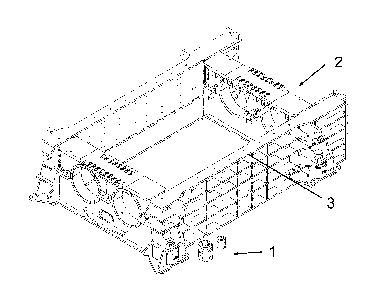
Figure 1 shows a machine housing 2 of a roller crusher as an exemplary
embodiment of a
comminuting machine of a comminuting plant according to the invention. It can
be seen that two
displacement apparatus 1 can be arranged in the housing wall 3. The rear
displacement
CA 2982724 2017-10-17
7
apparatus is shown in the mounted state and the front displacement apparatus
is shown as an
exploded diagram in a dismantled state. Two further displacement apparatus are
arranged on
the opposite housing wall but are covered and therefore not visible in Fig. 1.
Figures 2-6 show details of the housing wall 3 of Fig. 1 in a region of the
displacement
apparatus 1 in the mounted state. The housing wall 3 is part of the machine
housing and has a
structure of reinforcing ribs 14. The reinforcing ribs 14 are welded to other
steel plates for
reinforcement and thus help to provide the necessary mechanical strength of
the housing wall 3.
In the example shown, the displacement apparatus 1 has a lifting apparatus,
which is mainly the
hydraulic cylinder 4. The lifting apparatus can push a support element 16,
which can be seen in
Figures 5 and 6, of the displacement apparatus 1 downwards out of the housing
wall 3 and in
the process lift the comminuting machine in the region of the displacement
apparatus 1. In the
exemplary embodiment shown, the use of the hydraulic cylinder 4 is intended
only when the
comminuting machine is stopped at a location, to push the support element 16
far enough away
from the hydraulic cylinder 4 to open a pressure element introduction opening
6 for introducing
or removing a pressure element 5. During a displacement process, however, the
hydraulic
cylinder 4 is preferably relieved and the load in the region of the
displacement apparatus 1 is
directed via the support element 16 and the pressure element 5 into the
reinforcing rib 14
situated above the pressure element 5 or initially into a threaded ring 20
serving to fasten the
hydraulic cylinder 4. The pressure element 5 directs the effective forces as a
pressure plate
over a large area into the housing wall 3 so that no stress peaks and damage
can occur in this
region during the process of displacing the comminuting machine. Below the
pressure element
5, the design element of a wall or reinforcing rib 15 shaped as an open
cylinder is shown, which
acts as a support element guide for the cylindrical support element 16 behind
it.
In the exemplary embodiment shown, the comminuting plant includes the load-
bearing structure
10, a section of which is shown, the rails 7 being laid on the load-bearing
structure 10 in two
directions, specifically in an X direction and a Y direction. The comminuting
machine can be
displaced on its displacement apparatus 1 on the load-bearing structure 10 in
a substantially
horizontal plane. In the displacement position shown in Fig. 2, the support
element 16 and the
comminuting machine thereon stand on a wheel 17, which can be seen in Figures
5 and 6, and
there is a possibility of displacement in the Y direction. Rail guides 8 are
arranged axially next to
the wheel 17 and fit over the rail 8 in a forked manner in Fig. 2, preventing
movement in the X
direction and only allowing movement in the Y direction. The cylindrical
support element 16 of
the displacement apparatus shown is rotatable about the Z axis and can be
locked with a
locking element 9 at two angles, specifically at 00 for displacement in the X
direction and at 90
CA 2982724 2017-10-17
8
for movement in the Y direction. In the exemplary embodiment shown, the
locking element 9 is
a cuboid bar, which is secured in its inserted position against accidentally
sliding out by means
of the securing element, which can also be seen. The locking element 9 can be
seen in its
entirety in the pulled-out position in Figure 4.
The load-bearing structure 10 has a turntable 11 with a rail segment 12 formed
thereon, which
is rotatable about the Z axis about a central, vertically oriented pivot. The
turntable 11 can be
locked either in the X orientation or in the Y orientation with the two
visible bolts. In the middle of
the rail segment 12 shown, there is a cylindrical recess 13, in which the
wheel 17 is provided
during simultaneous rotation of the turntable 11 and the support element 16.
Figure 3 shows a somewhat smaller detail of the displacement apparatus 1, in a
standing
position in which the pressure element 5 is kept fastened on its rest and the
hydraulic cylinder 4
is retracted, so that the comminuting machine stands directly or indirectly on
the load-bearing
structure 10 and thus e.g. can be used productively to crush rock or can be
maintained. In
Figure 4, a pressure element receiving opening 6 can be seen, since the
pressure element 5
has been manually removed. Via the opening of the pressure element receiving
opening 6 there
is a view of the cylindrical support element 16, which has an annular collar
at the top on which
the pressure element 5 is placed. Here, the pressure element 5 has been taken
out, stored and
secured by means of screw-fastenings at a storage location inside the housing
wall 3, as can be
seen in Figure 4. The inner raised cylindrical edge inside the annular collar
serves as a stop for
the horseshoe-shaped pressure element 5 when the latter is inserted into the
pressure element
receiving opening 6. The pressure element 5 has a retaining plate and a
handle. In Figures 3
and 4, shims (not shown) are arranged between the load-bearing structure 10
and the housing
wall 3, so that the weight of the comminuting machine acts on the shims and
not on the
displacement apparatus 1.
Figure 4 shows the displacement apparatus 1 during conversion from the Y
orientation of the
cylindrical support element 16 as shown in Figures 2 and 6 to the X
orientation shown in Fig. 5.
In Figures 5 and 6, the housing wall 3 is shown partially open to allow a view
of internal parts of
the displacement apparatus 1. The cylindrical support element 16 is a
perforated cylinder with a
cuboid cut-out 18 for receiving the wheel 17. Owing to the cuboid cut-out 18,
the support
element in the exemplary embodiment shown has the form of a fork which, at the
same time,
acts as a guide for the wheel 17 and also forms the forked rail guide 8. In
other exemplary
embodiments which are not shown, the rail guide is implemented differently,
for example by a
double-flange on the wheel (17).
CA 2982724 2017-10-17
9
In the exemplary embodiment shown, the wheel 17 and the locking element 9 have
substantially
the same width as the cuboid cut-out 18, so that the cut-out 18 can be used as
a guide for the
wheel 17 during displacement and as a guide for the locking element 9 when the
lifting
apparatus is raised and lowered. A cylindrical and cuboid cut-out 19 in the
support element 16
serves for the introduction of a wheel axis in its cylindrical part and as a
guide groove for the
locking element 9 in its cuboid part with height adjustment of the support
element 16 and
simultaneously locked angular position. In the depictions of Figures 4 and 5,
the locking element
9 is outside its guide in the displacement apparatus 1, so that the
cylindrical support element 16
can be rotated in its support element guide formed from reinforcing ribs 15
shaped as open
cylinders. A key 21 which is used for manually performing this rotation and
has pins for
engagement in corresponding holes in the collar of the support element 16 is
likewise shown.
During this rotation, the forked rail guide 8 fits over the rail segment 12 of
the turntable 11, so
that the angle of the previously released turntable 11 is set at the same time
as the angle of the
displacement apparatus 1 and of the support element 16.
After rotation, the angular position of the support element 16 is locked with
the locking element
9 and the angular position of the turntable ills locked with the bolt provided
for this purpose.
Thanks to its angular adjustability, the displacement apparatus 1 shown can be
used universally
and efficiently for movements both in the X direction and in the Y direction.
Therefore, multi-
stage displacement processes can be carried out quickly and safely in a
sequence of different
directions. The presented displacement apparatus thus helps to provide a high
degree of
availability of the comminuting plant according to the invention.
CA 2982724 2017-10-17
10
Reference symbols
1 Displacement apparatus of a comminuting machine
2 Machine housing
3 Housing wall
4 Hydraulic cylinder
Pressure element
6 Pressure element introduction opening
7 Rail
8 Rail guide
9 Locking element
Load-bearing structure
11 Turntable
12 Rail segment on turntable
13 Recess
14 Reinforcing ribs
Reinforcing rib shaped as hollow cylinder
16 Support element
17 Wheel
18 Cuboid cut-out
19 Cylindrical and cuboid cut-out
Threaded ring
21 Key
CA 2982724 2017-10-17