Note: Descriptions are shown in the official language in which they were submitted.
1
Method and system for anaerobic treatment of organically loaded wastewater
Field of the invention
The present invention relates to a method for anaerobic treatment of an
organic
wastewater and organic waste streams. In a further aspect the invention
relates to a
system for anaerobic treatment of such an organic wastewater and organic waste
streams.
Prior art
Food and beverage production plants are major wastewater contributors and
often have food waste. Particularly plants with wastewaters with a significant
total
suspended solids (TSS) and/or fats, oils and greases (FOG) like in the dairy,
meat and
chicken industry need to pre-treat their wastewater before high rate anaerobic
reactors
can be applied. This pre-treatment generally includes undesirable chemical
treatment
and generates a concentrated side stream which needs to be dealt with.
In parts of the food and beverage industry many high-rate reactors are
installed,
typically on wastewaters with high dissolved organic matter and low total
suspended
solids (TSS) and Fats, Oils and Greases (FOG). These high rate reactors, such
as UASB
(Upflow Anaerobic Sludge Bed) and EGSB (Enhanced Granular Sludge Bed) reactors
depend on the granulation of the consortia of biomass in the reactor. In many
occasions
there are problems with maintaining the granular sludge, due to the presence
of solids,
oils and greases or other inhibiting factors. Wastewater with high levels of
COD
(Chemical Oxygen Demand), TSS and FOG can be found in many parts of the food
and
beverage industry, such as ice cream, chocolate, candy, vegetable, dairy and
cheese
factories. Also Palm Oil Mill Effluent (POME) falls into this category.
Traditionally, the treatment process for such factories consists of a pre-
treatment step, typically a physical-chemical treatment, to remove the free
fats and
solids, sometimes followed by high-rate anaerobic treatment, then generally
followed
by an aerobic biological treatment plant to achieve the discharge
requirements. The pre-
treatment step is essential for producing a wastewater which is suitable for
the aerobic
micro-organisms. Known issues with not properly pre-treated wastewaters are:
foaming, sludge bulking, grease layers on aeration tanks, and poor settling
characteristics. The result of a process with chemical pre-treatment is a good
quality
DateRegue/Date Received 2022-06-27
2
wastewater, but it also produces a chemically treated sludge from the pre-
treatment and
excess aerobic biological sludge.
In the past decades the sludge from pre-treatment systems has become an ever-
increasing problem to dispose of at ever increasing disposal costs. Decades
ago these
organic sludges could still be spread over land or mixed with other products
to produce
fodder as food for animals (pigs). More recently, in various countries, many
of these
sludges have to be incinerated. Lately, there is a trend to use these sludges
as co-
substrate in anaerobic digestion plants, yet still at a cost to the factory
producing it.
Besides these sludges from the wastewater treatment processes, food factories
are also
producing organic wastes, which can either be rejected batches, returned
products,
concentrates produced during CIP cleaning, spills, et cetera.
To deal with the sludges of pre-treatment systems (physical-chemical)
anaerobic digestion systems are often installed. In these cases chemicals and
equipment
are needed to produce these sludges. An alternative is to mix the wastewater
and
organic waste together and treat it in an anaerobic digester, such as
disclosed in US
patent publication US 5,015,384. Since the wastewater is relatively diluted
and the
anaerobic digestion requires a solids retention time (SRT) of at least 15-20
days, such a
digestion plant would require a retention time equal to the SRT. However, a
reactor
with a retention time of over 10 days is generally not economical.
From WO 2013/155631 an anaerobic digester is known for treatment of
industrial wastewater in which the influent stream may be a single stream or a
composite stream of two or more waste streams. A solid-liquid separation
device which
may be a sludge screw thickener, treats a stream from the digester in a
recirculation
loop. The solids portion is returned to the digester to increase the solids
retention time
and the TSS in the digester. This allows the SRT to be controlled separately
from the
hydraulic retention time HRT. A liquid portion with less than 5% solids in the
stream is
removed and treated further in a polishing unit.
It is an object of the present invention to provide effective separation of
organically loaded waste streams using an anaerobic reactor. It is another
object of the
invention to provide an anaerobic waste water treatment method using reduced
amounts
of coagulant and/or flocculant polymer. It is a further object of the
invention to provide
an anaerobic waste water treatment method in which the coagulant and/or
flocculant
DateRecue/Date Received 2022-06-27
3
polymer may be cost effective and is able to use metal complexes containing
for
instance Al or Fe.
Another object is to provide a relatively low cost separator downstream from
the anaerobic reactor.
A further object is to provide downstream from the anaerobic reactor a
separator that can be operated with a gas that is derived from the ambient.
Summary of the invention
According to the present invention, a method of anaerobic treatment of an
organic waste stream is provided that comprises the steps of:
- feeding the organic waste stream to an anaerobic reactor,
- separating a reactor mixture originating from the anaerobic reactor in a
first
separating unit into a first fraction containing between 50 % and 80 % of the
solids by weight and a second fraction,
- feeding the second fraction from the first separating unit into a Dissolved
Gas
Floatation (DGF) unit,
- separating in the DGF unit the second fraction into a sludge fraction and
a
liquid fraction, and
- feeding the first fraction and the sludge fraction back into the
anaerobic reactor.
By using a first separating unit, the output stream of the anaerobic reactor
can
be concentrated and the solids can for the largest part be fed back into the
reactor. The
liquid fraction from the first separating unit contains reduced amounts of TSS
and can
be effectively treated in a dissolved gas floatation (DGF) unit of relatively
small size
(decrease in size between 50-80%). The sludge fraction at the output of the
DGF unit is
fed back into the anaerobic reactor, whereas the effluent from the DGF is of
relatively
high quality.
The method according to the invention provides a very good solution to treat
both an organic waste wastewater and organic waste solids in a single process,
with a
high efficiency and allowing for a rather compact system design. By returning
the
biomass to the reactor, the Solids Retention Time (SRT) can be extended
largely over
the Hydraulic Retention Time (HRT). Typically the solids-liquid separation is
a
Dissolved Biogas Flotation (DBF) system. The pre-separator upstream of the
DBF/DGF may be of the filter type, like a vacuum filter press or a cloth
filter, a
DateRecue/Date Received 2022-06-27
4
dynamic filter based on centrifugal forces, like a cyclone or a centrifuge or
a DGF
without or relative little the addition of chemicals. The method according to
the
invention is beneficial for those fluids for which the SRT needs to be
substantially
higher than the HRT to obtain a stable and good process.
With the above method one or more waste streams can be dealt with in one
system and a high level of conversion to biogas can be achieved. To comply
with local
discharge regulations a post-aerobic biological treatment may be required. The
excess
sludge from this aerobic system can be returned to the anaerobic reactor,
which is
another advantage over high rate (UASB-type) reactors. The method according to
the
invention provides approximately 20% lower operational costs compared to a
method
wherein a chemical treatment step is followed by a step involving a UASB-type
reactor.
In an embodiment of the method according to the invention, at an outlet of the
first separating unit a flocculant and/or coagulant is added to the second
fraction in a
dosage of between 1-12 g flocculant/kg dry solids, preferably between 3-9 g
flocculant/kg dry solids, more preferably between 3-6 kg flocculant/g dry
solids. The
relatively low amounts of flocculant polymer allow effective operation of the
Dissolved
Gas Floatation unit.
The coagulant may comprise relatively cheap compounds such as metal
complexes, for instance Al or Fe in a dosage of between 50-1000 ppm,
preferably
between 100-400, so that it is more cost-effective.
The DGF unit may be operated using biogas from the anaerobic reactor to
minimise the oxygen level is in the feedback stream to the anaerobic reactor.
Instead of
biogas air can be used after removing the majority of the oxygen.
However, by using the method according to the invention it was found that also
a
Dissolved Air Floatation (DAF) unit may be used as a separator. In the process
of
feeding the sludge from the DAF back into the anaerobic reactor, the oxygen in
the
sludge stream was found not inhibiting for the anaerobic processes in this
reactor.
Brief description of drawings
The present invention will be discussed in more detail hereinafter based on an
exemplary embodiment with reference to the sole drawing.
DateRegue/Date Received 2022-06-27
5
Detailed description of exemplary embodiments
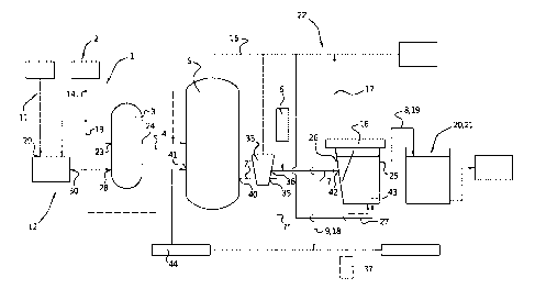
Figure 1 shows a system 22 for anaerobic treatment of an organic wastewater
and organic waste streams 1. The system 22 comprises an equalization buffer 3,
for
instance in the form of a pump sump or a mixing tank, provided with a primary
inlet 23
arranged to receive a primary stream 2 of organic wastewater. The organic
wastewater
1 may for instance comprise wastewater from a dairy, chocolate or cheese
factory,
comprising slurries, liquids (such as in the case of chocolate factories). An
anaerobic
reactor 5 is connected to an outlet 24 of the equalization buffer 3. An outlet
40 of the
reactor 5 is connected to a first separating unit 33. A first outlet 35 of the
first
separating unit 33 is connected to a feedback inlet 41 of the reactor 5 for
feeding back a
stream 7" containing between 50 % and 80 % of the solids by weight into the
reactor 5.
A second outlet 36 of the pre-separating unit 33 is connected to an input 42
of a
separator 16 for supplying a low solids stream 7 into the separator 16. In the
separator
16, which may be DGF unit or a DAF unit as described in EP 1 735 070 in the
name of
the applicant, the reactor mixture 7' is separated into a liquid fraction 8
and a sludge
fraction 9. The sludge fraction 9 is fed back to the feedback inlet 41 of the
reactor 5.
The anaerobic reactor 5 may be cylindrical with a double membrane roof. If
desired, multiple subsequent anaerobic reactors 5 may be used, wherein the
first reactor
is a relatively large reactor and the second reactor is fitted with a membrane
roof for
gas storage (not shown). Preferably, mixing devices (not shown) are installed
in the
reactor 5 to enhance mixing and avoid stratification. The temperature in the
reactor 5
may be controlled by steel tubing in the wall of the reactor 5, which act as a
heat
exchanger. The hydraulic retention time may vary between 1-14 days. The
organic
loading will typically depend on substrates and solids and will typically be
between 2-
20, preferably 3-7 kg COD/m3/day. Recycling of solids is required to achieve
the
desired organic loading and to attain a sufficiently long solids retention
time (SRT).
Alternatively, the equalization buffer 3 can be left out, such that the
primary 2 and
secondary 11 streams flow directly to the reactor 5 (as indicated by the
dashed lines).
A flocculant and/or coagulant feeder 6 is provided and is connected to the
inlet
42 of the separator 16, wherein the feeder is arranged for dosing the
flocculant at 1-12,
preferably 3-9, more preferably 3-6, g flocculant/kg dry solids. The separator
16 of
figure 1 can be a dissolved biogas flotation (DBF) separator 16, comprising a
liquid
fraction outlet 25, a sludge fraction outlet 26 connected to the feedback
inlet 41 of the
DateRegue/Date Received 2022-06-27
6
anaerobic reactor 5, and a secondary inlet 27 that is arranged to receive
biogas from the
anaerobic reactor 5.
Instead of the biogas introduced into the reactor 16 via the secondary inlet
27,
treated air containing less oxygen or untreated air may be introduced into
secondary
inlet 43, so that the reactor is a Dissolved Air Floatation unit. The air may
be supplied
by a compressor 37 that draws in air from the ambient. The air supply has been
indicated in a dashed line and may be used in combination with or instead of
supplying
biogas via the inlet 27.
A further separator unit 44 may be comprised upstream of the inlet 41 of the
anaerobic reactor to further remove liquid from the stream returned to the
anaerobic
reactor to 4-30% TSS.
According to the invention, the equalization buffer 3 further comprises a
secondary inlet 28 arranged to receive a secondary stream 11 comprising
organic waste
solids. The separator 16 may be gastight to prevent biogas from escaping
and/or
exposing the anaerobic bacteria to outside air, which, depending on the type
of bacteria,
could kill them. It was found however, that the use of the pre-separating unit
33 allows
supply of air into the separator 16 without adversely affecting the anaerobic
reactions in
the reactor 5.
The system 22 may further comprise a pre-treatment unit 12 comprising a main
inlet 29 and an outlet 30 connected to the secondary inlet 28 of the
equalization buffer
3. The pre-treatment unit 12 can be a de-packing unit, cutting unit, shredding
unit,
pasteurisation unit, sterilisation unit, oxidation unit, solubilisation unit,
hydrolysis unit
or any combination thereof. The type of pre-treatment depends on the type of
product,
country (regulations) and process requirements. A screen may be used to remove
larger
debris, like cloth, wood or paper. Furthermore, a first separator (indicated
by the
frustoconical shape, with reference numeral 33) may be installed before the
DGF 16, to
be able to dose a flocculant to reduce tank volume even further. Such a pre-
separator
33 may be of the filter type, like a vacuum filter press or a cloth filter, a
dynamic filter
based on centrifugal forces, like a cyclone or a centrifuge or a DGF, without
or with
little addition of chemicals.
In an exemplary configuration (not shown), used by the applicant in a secure
testing environment, the system 22 is used with two anaerobic reactors 5, with
a
volume of 600-900, such as 750 m3, each. A pipe reactor with flocculant dosing
is used.
DateRegue/Date Received 2022-06-27
7
This system can for instance be used with a chocolate factory. A typical
wastewater
volume then is 100 ni3/d with a COD concentration varying between 10-60 g/1 at
an
average of 37 g/l. Based on an effective liquid volume of 1300 in3 the organic
loading
then is 2,5-3,0 kg COD/m3/d on average. The separator/flotation device 16 is
operated
at 5 m3/h. Applicant has been able to achieve consistently stable results with
the above
parameters and flocculant dose used. TSS and COD removal percentages of more
than
95% were achieved for the wastewater from the DBF 16.
According to the invention, the method of anaerobic treatment of an organic
wastewater and organic waste streams 1, comprises the steps of
a) feeding a primary stream 2 of organic wastewater 1 to an anaerobic reactor
5;
b) feeding a secondary stream 11 comprising organic waste solids to the
anaerobic
reactor 5;
d) separating a reactor mixture 7' originating from the anaerobic reactor 5
into a liquid
fraction 8 and a sludge fraction 9; and
e) feeding, at least in part, the sludge fraction 9 back to the anaerobic
reactor 5.
Preferably, the method is carried out in mesophilic conditions (25-42 C),
although theimophilic conditions (43-60 C) can also be used.
The method step of (a) feeding the primary stream 2 of organic wastewater and
organic waste streams 1 further may comprise the step of feeding the secondary
stream
11 of the organic waste solids to the equalization buffer 3. Feeding the
secondary
stream 11 of organic waste solids may comprise proportionally feeding the
second
stream 11 to the equalization buffer 3 to obtain a more consistent mixture. As
stated
before, feeding the secondary stream of organic waste solids may comprise a
pre-
treatment 12 thereof comprising de-packing, cutting, shredding,
pasteurisation,
sterilisation, solubilisation or hydrolysis, or any combination thereof.
Furthemiore, the method step of (a) feeding the primary stream 2 of organic
wastewater further may comprise separating the primary stream 2 of organic
wastewater into a first fraction 13 and a second fraction 14, and feeding the
first
fraction 13 to the equalization buffer 3 and the second fraction 14 to the pre-
treatment
12. The method step of feeding the buffer mixture 4 further comprises
preheating the
buffer mixture 4 from the equalization buffer 3 by a heating unit (not shown).
The
heating unit can also be used to heat raw waste water entering the
equalization buffer 3.
DateRegue/Date Received 2022-06-27
8
Preferably, a heat recovery system is used, wherein heat from wastewater is
used to
heat further wastewater, for instance via a heat exchanger.
The method step of separating the reactor mixture 7' may comprise feeding
biogas 15 from the anaerobic reactor to a dissolved biogas flotation separator
(DGF)
16. Therein, 5-30, preferably 5-20, more preferably around 10-15 1 biogas/kg
solids, is
fed to the dissolved biogas flotation separator (DBF) 16. The method further
may
comprise the step of collecting biogas 17 from the dissolved biogas flotation
separator
(DBF) 16 for further use, such as for heating or generation of energy.
The method step of feeding, at least in part, the sludge fraction 9 back to
the
anaerobic reactor 5 further comprises collecting, at least in part, the sludge
fraction 18
for further use.
Advantageously, wastewater 19 from the separator 16 is subsequently subjected
to a polishing step 20. The polishing step 20 preferably comprises aerobic
treatment 21.
Excess sludge originating from the polishing step 20 can be fed back to the
anaerobic
reactor 5.
DateRegue/Date Received 2022-06-27