Note: Descriptions are shown in the official language in which they were submitted.
CA 02982917 2017-10-16
WO 2016/195752 PCT/US2015/066679
1
COMPRESSIVE RESIDUAL STRESS-HARDENED DOWNHOLE TOOL SHAFT
REGION
TECHNICAL FIELD
The present disclosure relates generally to downhole tools, such as rotary
drill
bits, with a compressive residual stress-hardened shaft region.
BACKGROUND
Various types of downhole tools are used to form wellbores in downhole
formations. These downhole tools including rotary drill bits, reamers, core
bits, under
reamers, hole openers, and stabilizers. Rotary drill bits include fixed-cutter
drill bits,
roller cone drill bits, and hybrid drill bits. Rotary drill bits may be
manufactured of
materials such as polycrystalline diamond compact and metal-matrix composite
(MMC).
A rotary drill bit may include more than one type of material. For instance
PDC drill bits
are often also MMC drill bits.
BRIEF DESCRIPTION OF THE DRAWINGS
For a more complete understanding of the present invention and its features
and
advantages, reference is now made to the following description, taken in
conjunction with
the accompanying drawings, in which:
FIGURE 1 is an elevation view of a drilling system in which a downhole tool
containing a compressive residual strength-hardened region may be used;
FIGURE 2 is an isometric view of a fixed-cutter drill bit with a shank
including a
threaded connector oriented upwardly;
FIGURE 3 is an isometric view of a fixed-cutter drill bit with a mandrel and a
shank including a threaded connector oriented upwardly;
FIGURE 4 is a cross-sectional view of the shank of the drill bit of FIGURE 2
with
a compressive residual strength-hardened threaded connector;
CA 02982917 2017-10-16
WO 2016/195752 PCT/US2015/066679
2
FIGURE 5 is a graph of the fatigue strength and applied stress for the
threaded
connector shown in FIGURE 2 when the threaded connector is subjected to a
bending
load; and
FIGURE 6 is a flow chart of a method for creating a compressive residual
strength-hardened shaft region by causing an allotropic phase transformation
in a
precursor shaft region.
DETAILED DESCRIPTION
During a drilling operation, various downhole tools, including drill bits,
coring
bits, reamers, hole enlargers, or combinations thereof may be lowered into a
partially
formed wellbore and used to further form the wellbore, for instance by
drilling the
wellbore deeper into a formation or by increasing the diameter of the
wellbore. These
downhole tools are subject to a variety of mechanical stresses, particularly
during contact
with the formation. For instance, the shaft of the drill bit may experience
different
stresses than the head of the bit. Different parts of the shaft may also
experience different
stresses from one another. The present disclosure provides a downhole tool,
such as a
drill bit, in which a region of the shaft, typically a metallic region, has
been hardened by
imparting a compressive residual stress to that region by causing an
allotropic material in
the region to undergo an allotropic phase transformation from a first
allotrope to a second
allotrope while forcing the second allotrope to occupy the same physical space
as the first
allotrope, thereby creating the compressive residual stress.
Allotropic materials can have two or more different physical structures while
in
the same physical state (i.e., solid, liquid, or gas). These different
physical structures are
referred to as allotropes. The present disclosure relates to allotropic
materials with at least
.. two allotropes in the solid state. Often different allotropes in the solid
state have different
crystal structures, although other differences in physical structure may be
found in some
allotropic materials. The different physical structures of different
allotropes confer
different physical properties. Graphite (pencil lead) and diamond are a
readily understood
examples of how different the physical properties of different allotropes may
be.
CA 02982917 2017-10-16
WO 2016/195752 PCTfUS2015/066679
3
Although both materials are composed of nearly pure carbon, graphite may be
flaked
with a fingernail, while diamond is the hardest substance known. The
difference is due
entirely do the different crystal structures of the two different allotropes.
An allotropic phase transformation, as used herein, occurs when an allotropic
material changes from one allotrope to another while remaining a solid and
without
reaction with another chemical. Typically, changing from one allotrope to
another causes
an increase or a decrease in the atomic packing density, a crystal lattice
parameter (if at
least one of the allotropes is a crystal), or both. An allotropic phase
transformation may
be caused by any number of conditions, which commonly include a threshold
level of or
amount of change in pressure, temperature, or both. For example, the graphite
allotrope
undergoes an allotropic phase transformation to the diamond allotrope, but
only under
very high temperature and pressure. Most allotropic phase transformations of
interest in
forming a downhole tool as disclosed herein do not require such extreme
conditions.
Allotropic elements include Americium (Am), Beryllium (Be), Calcium (Ca),
Cerium (Ce), Curium (Cm), Cobalt (Co), Dysprosium (Dy), Iron (Fe), Gadolinium
(Gd),
Hafnium (Hf), Holmium (Ho), Lanthanum (La), Manganese (Mn), Neodymium (Nd),
Neptunium (Np), Promethium (Pm), Praseodymium (Pr), Plutonium (F'u), Sulfer
(S),
Scandium (Sc), Samarium (Sm), Tin (Sn), Strontium (Sr), Terbium (Tb), Thorium
(Th),
Titanium (Ti), Uranium (U), Yttrium (Y), Ytterbium (Yb), and Zirconium (Zr).
Allotropic materials include alloys of any of these allotropic elements, such
as steel (Fe¨
C), in which the allotropic element may still be present as at least two
different
allotropes.
Allotropes may be detected and distinguished from one another using any of a
variety of known non-destructive or destructive measurement methods. For
instance
allotropes may be distinguished using X-ray diffraction.
According to the present disclosure, a precursor region is formed on a
downhole
tool shaft, which may include a region in an unthreaded part of the shank, in
a threaded
connector part of the shank, or a region in a mandrel (also sometimes referred
to as a
blank). The precursor region may be formed when the shaft is formed, prior to
formation
CA 02982917 2017-10-16
WO 2016/195752 PCT/US2015/066679
4
of a downhole tool on the shaft, during formation of a downhole tool on the
shaft, or after
formation the downhole tool on the shaft, but before use of the downhole tool.
The
precursor region includes an allotropic material that can undergo an
allotropic phase
transformation to cause a compressive residual stress in the region. For
instance, the
allotropic material in the precursor region may be a first allotrope with a
higher packing
density, at least one shorter lattice parameter (if a crystal), or both, than
the second
allotrope formed by the allotropic phase transformation. The allotropic
material is a solid
and is constrained in at least one dimension by the remainder of the shaft
such that it
occupies the same physical space as the first allotrope, so a compressive
residual stress is
created in the region.
For example, the precursor region may include the austenite allotrope of Fe,
which has a face centered cubic (FCC) crystal structure. When the precursor
region is
cooled, the Fe undergoes an allotropic phase transformation to the ferrite
allotrope, which
has a body centered cubic (BCC) crystal structure. The ferrite allotrope of Fe
has a higher
packing density than the austenite allotrope, so a residual compressive stress
in the region
is created by the allotropic phase transformation. In other examples, after
the Fe
undergoes an allotropic phase transformation to a ferrite allotrope, the Fe
may have
entrapped carbon and have a body centered tetragonal (BCT) crystal structure.
Various methods for measuring compressive residual stress are known. Methods,
such as X-ray diffraction and hardness profile testing, are compatible with
measuring
compressive residual stress in the present disclosure. X-ray diffraction may
also be used
to determine the allotrope present in any portion of the downhole tool
Although some
testing may be non-destructive, such as X-ray diffraction measured on the
surface of a
region, other testing, such as testing of the interior of a region or hardness
testing, may be
destructive. If destructive testing is used to determine compressive residual
stress of an
allotrope, then representative samples may be used and the test results may be
assumed to
apply to other downhole tools of the same construction formed in the same way.
A compressive residual stress increases crack-resistance of a region as
compared
to a similar region that did not undergo an allotropic phase transformation or
another
CA 02982917 2017-10-16
WO 2016/195752 PCT/US2015/066679
region of the shaft that does not contain the allotropic material. Compressive
residual
stress helps arrest any cracks that may form or propagate by essentially
squeezing the
crack, especially at its ends. Crack-resistance may be measured using any of a
number of
known measurements techniques, which are usually not dependent on how the
material
5 was formed. Crack-resistance may focus on the ability to resist
propagation of cracks that
have formed, rather than the ability to resist formation of cracks in the
first place. Cracks
in a downhole tool may be detected using any of a number of known detection
techniques
including fluorescent-penetrant dye inspection, ultrasonic testing, and X-ray
testing.
A compressive residual stress in a region may also improve its erosion
resistance,
stiffness, strength, toughness, or any combination thereof. These improved
properties
may be achieved instead of or in addition to improved crack-resistance as
compared to a
similar region that did not undergo an allotropic phase transformation or
another region
of the shaft that does not contain the allotropic material. These properties
may also be
measured using known measurement techniques, which are also not usually
dependent on
how the material was formed.
Typically the compressive residual stress-hardened region includes part of a
surface of the shaft and also extends into the shaft. Typically, the
compressive residual
stress-hardened region extends into the shaft at least 0.1 mm, at least 1 mm,
at least 10
mm, or at least 250 mm, as well as between any combinations of these
endpoints. When
the compressive residual stress-hardened region is annular, its thickness may
depend on
the external diameter of the shaft in the compressive residual stress-hardened
region.
Although the downhole tools and methods discussed herein refer to a single
precursor region and single compressive residual stress-hardened region for
simplicity, a
shaft, including a single part of the shaft, may include a plurality of such
regions.
Furthermore, different precursor regions or corresponding compressive residual
stress-
hardened regions or even the same precursor region or compressive residual
stress-
hardened region may contain different allotropic materials. In addition,
different
precursor regions and different compressive residual stress-hardened regions
may be
formed at different times and different types of heating or multiple heating
steps may be
CA 02982917 2017-10-16
WO 2016/195752 PCT/1JS2015/066679
6
used to cause an allotropic phase transformation in different precursor
regions or different
allotropic materials. Furthermore, although the allotropic material is
referred to herein as
occupying the same physical space after the allotropic phase transformation,
some
variation in physical dimensions, particularly in directions where the
material is not
constrained, may occur. Typically this variation in any direction will be less
than 1% of
the length of that direction, or the volume occupied by the first allotrope
will not change
by more than 10%.
Aspects of the present disclosure and its advantages may be better understood
by
referring to FIGURES 1 through 6, where like numbers are used to indicate like
and
corresponding parts.
FIGURE 1 is an elevation view of a drilling system in which a downhole tool
containing a hardened region may be used. Drilling system 100 includes a well
surface or
well site 106. Various types of drilling equipment such as a rotary table,
drilling fluid
pumps and drilling fluid tanks (not expressly shown) may be located at well
surface or
well site 106. For example, well site 106 may include drilling rig 102 that
may have
various characteristics and features associated with a land drilling rig.
However,
downhole tools incorporating teachings of the present disclosure may be
satisfactorily
used with drilling equipment located on offshore platforms, drill ships, semi-
submersibles, and/or drilling barges (not expressly shown).
When configured for use with a drill bit, drilling system 100 includes drill
string
103 associated with drill bit 101, typically through a bottom hole assembly
(BHA). The
drilling system is used to form a wide variety of wellbores or bore holes such
as generally
vertical wellbore 114a or directional wellbore, such as generally horizontal
wellbore
114b, or any combination thereof. Drilling system 100 may be configured in
alternative
ways for other downhole tools having a shaft.
In the present disclosure, drill bit 101 or another downhole tool in drilling
system
100 includes a compressive residual stress-hardened region on its shaft. The
compressive
residual stress-hardened region may optimize drill bit 101 or other downhole
tool for the
conditions experienced during the drilling operation to increase the life span
of drill bit
7
101 or other downhole tool. Although drill bit 101 is depicted as a fixed-
cutter drill bit,
any drill bit having a shaft with a compressive residual stress-hardened
region may be
used in drilling system 100.
FIGURE 2 and FIGURE 3 are isometric views of fixed-cutter drill bits oriented
upwardly. Drill bit 101 formed in accordance with teachings of the present
disclosure
may have many different designs, configurations, and dimensions according to
the
particular application of drill bit 101.
In FIGURE 2, drill bit 101 includes shaft 151 and head 150. Shaft 151 includes
shank 152 with threaded connector 155. Shank 152 is securely attached to head
150 such
that it will not separate from head 150 during normal operation of drill bit
101. Shank
152 may be solid, but typically it contains a fluid-flow passageway as
depicted in
FIGURE 4. Shank 152 or threaded connector 155 include at least one compressive
residual stress-hardened region containing an allotrope of an allotropic
material that
creates at least a part of the compressive residual stress.
In FIGURE 3, drill bit 101 also includes shaft 151 and head 150, but shaft 151
includes shank 152, threaded connector 155, and mandrel 153. Mandrel 153 is
securely
attached to head 150 such that it will not separate from head 150 during
normal operation
of drill bit 101. Shank 152 is securely attached to mandrel 153 such that it
will not
separate from mandrel 153 during normal operation of drill bit 101. For
instance, shank
152 may be welded to mandrel 153, for example by weld 154 in an annular weld
groove.
Shank 152 may be solid, but typically it contains a fluid-flow passageway as
depicted in
FIGURE 4. Mandrel 153 also may be solid, but typically contains a fluid-flow
passageway similar to that of shank 152.
Referring again to both FIGURE 2 and FIGURE 3, threaded connector 1 55 [also
referred to as an American Petroleum Institute (API) connector] may be used to
releasable engage drill bit 101 with drill string 103 or FIGURE 1, typically
through the
BHA. When engaged with drill string 103, drill bit 101 may be rotated relative
to bit
rotational axis 104 in direction 105. Threaded connector 155 includes threads
that are
CA 2982917 2019-02-19
8
machined into threaded connector 155. Threaded connector 155 may be welded to
shank
152 after the allotropic phase transformation is complete.
Although any part of shaft 151, including multiple parts thereof, may contain
a
compressive residual stress-hardened region, typically a compressive residual
stress-
hardened region will be located at least on threaded connector 155.
Furthermore,
although shaft 151 or any part thereof may be formed from any material,
typically shank
152, threaded connector 155, and mandrel 153 (if present) are formed from a
metal or
metal alloy.
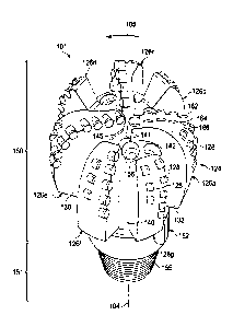
Drill bit 101 includes head 150 including one or more blades 126a-126g,
collectively referred to as blades 126, that are disposed outwardly from
exterior portions
of rotary bit body 124. Rotary bit body 124 may have a generally cylindrical
body and
blades 126 may be any suitable type of projections extending outwardly from
rotary bit
body 124. For example, a part of blade 126 may be directly or indirectly
coupled to an
exterior portion of bit body 124, while another part of blade 126 may be
projected away
from the exterior portion of bit body 124. Blades 126 formed in accordance
with the
teachings of the present disclosure may have a wide variety of configurations
including
substantially arched, helical, spiraling, tapered, converging, diverging,
symmetrical,
asymmetrical, or any combinations thereof.
Each of blades 126 may include a first end disposed proximate or toward bit
rotational axis 104 and a second end disposed proximate or toward exterior
portions of
drill bit 101 (i.e., disposed generally away from bit rotational axis 104 and
toward uphole
portions of drill bit 101). Blades 126 may have apex 142 that may correspond
to the
portion of blade 126 furthest from bit body 124 and blades 126 may join bit
body 124 at
landing 145. Exterior portions of blades 126, cutters 128 and other suitable
elements may
be described as forming portions of the bit face. Drill bit 101 includes
surfaces 130, 141,
162, 164 and 166.
Plurality of blades 126a-126g may have respective junk slots or fluid-flow
paths
140 disposed therebetween. Drilling fluids arc communicated through one or
more
nozzles 156.
CA 2982917 2019-02-19
CA 02982917 2017-10-16
WO 2016/195752 PCT/US2015/066679
9
Although bit body 124 and blades 126 may be formed from any material,
typically they are formed from a reinforcement material infiltrated with a
binder.
FIGURE 4 is a cross-sectional view of shank 152 with a compressive residual
strength-hardened region 206 on the exterior of threaded connector 155. Shaft
152 also
includes unthreaded part 202 and fluid-flow passage 204. Thickness 208 of
compressive
residual strength-hardened region 206 may be a function of diameter 210 of
threaded
connector 155. For example, as diameter 210 increases, thickness 208 may also
increase.
As a general rule, thickness 208 may be approximately one-sixth of diameter
206.
Compressive residual strength-hardened region 206 may have a higher crack
resistance, a higher erosion resistance, a greater stiffness, a greater
strength, a greater
toughness or any combination thereof as compared to unthreaded part 202.
Compressive
residual strength-hardened region 206, particularly when combined with a
softer
underlying shank material, may result in an increased lifespan for threaded
connector 155
as threaded connectors are prone to failure due to fatigue, overloading, or
both.
FIGURE 5 is a graph of the fatigue strength and applied stress for threaded
connector 155 shown in FIGURE 4 when subjected to a bending load. The fatigue
strength is shown as a function of depth from the surface of threaded
connector 155 by
line 402. Throughout compressive residual strength-hardened region 206, the
fatigue
strength remains high at approximately 1100 IVIPa. At approximately 1.5
millimeters
from the surface, the hardening effects of compressive residual strength-
hardened region
206 end and the fatigue strength decreases to approximately 460 M:Pa.
Line 404 illustrates the applied stress and line 406 illustrates the effective
applied
stress as a function of depth from the surface of threaded connector 155.
Effective
applied stress is the summation of applied stresses and residual stress at a
particular depth
from the surface. Due to the compressive residual stress in compressive
residual strength-
hardened region 206 at the surface and to a depth of 1.5 millimeters, the
magnitude of the
effective applied stress is less than the applied stress. Both the applied
stress and the
effective applied stress remain below the effective fatigue strength of
threaded connector
until approximately 2.4 millimeters below the surface. Therefore, crack
initiation is
CA 02982917 2017-10-16
WO 2016/195752 PCT/US2015/066679
delayed until this depth below the surface. In addition higher stresses are
required to
create a crack, thus creating crack-resistance in connector 155.
Prior to forming a compressive residual strength-hardened region, a precursor
region is first formed on the shaft of downhole tool, such as a drill bit. The
precursor
5 region may be formed on the shaft prior to formation of the downhole tool
including the
shaft. The precursor region may be formed during formation of the downhole
tool
including the shaft. The precursor region may also be formed after formation
of the
downhole tool including the shaft. In addition, for a downhole tool containing
multiple
precursor regions, the precursor regions may be formed at different times.
10 In some examples, if the shaft or a part of the shaft is formed from an
allotropic
material, the precursor region may simply be a region identified for
allotropic phase
transformation but otherwise no different than other parts of the shaft. In
other examples,
the precursor region may be attached to the shaft, for example by welding.
In other examples, the precursor region may include a coating. The coating may
be any type of allotropic material discussed herein. In some examples, the
coating may be
an alloy of the material from which the shaft or relevant part thereof is
made.
Alternatively or additionally, the coating may include an alloy that controls
the
temperature at which the allotropic phase transformation occurs. The coating
may be
applied using any suitable application technique, including spraying the
coating on the
shaft in the precursor region, applying a metal foil to the precursor region,
or dipping the
precursor region into a liquid coating, or any combination thereof. Such a
coating may
also be diffused into the downhole tool.
In still other examples, the precursor region may be formed in the shaft by
casting
the shaft from at least two different materials, at least one of which is an
allotropic
material located in the precursor region.
Regardless of when or how it is formed, at some point prior to the completion
of
manufacturing and eventual use of the downhole tool, the precursor region is
subjected to
heat to cause an allotropic phase transformation of the allotropic material,
forming a
compressive residual stress-hardened region in place of the precursor region.
CA 02982917 2017-10-16
WO 2016/195752 PCT/US2015/066679
11
FIGURE 6 is a flow chart of one such method 500. The steps of method 500 may
be performed by a person or manufacturing device that is configured to
identify precursor
regions and create conditions that transform the allotropic phase of the
allotropic material
in that region. Either the person or the manufacturing device may be referred
to as a
manufacturer.
In step 502 the manufacturer identifies a precursor region on shaft 151,
particularly on a metallic portion of shaft 151. The precursor region includes
a first
allotrope of an allotropic material identified herein. In step 504, the
precursor region is
heated to cause an allotropic phase transformation, which forms a compressive
residual
strength-hardened region with a second allotrope of the allotropic material.
Heating may include induction, flame, laser, electron beam, thermal radiation,
convection, friction, or combinations thereof. Induction heating is the
process of heating
an object through electromagnetic induction. Flame heating is the process of
heating an
object by exposing the object to a torch or flame. Laser heating is the
process of heating
an object with a laser beam. Electron beam heating is the process of heating
an object by
exposing an object to an electron beam. Thermal radiation heating is the
process of an
object by exposing the object to heat radiating off of another object.
Convection heating
is the process of heating an object by exposing the object to air currents
that have been
circulated over a heating element. Friction heating is the process of heating
an object by
exposing the object to heat generated by friction between the object and
another object.
Another trigger condition is the combination of heating and quenching where
the
allotropic material is heated followed by quenching to rapidly cool the
allotropic material
to finish the allotropic phase transformation.
Heating may also or alternatively include carburizing, nitridizing,
boronizing, or
combinations thereof. Carburizing, nitridizing, and boronizing further
increase the
compressive residual stress by introducing carbon (C), nitrogen (N), or boron
(B) as an
interstitial element in the compressive residual strength-hardened region. In
any of the
three processes, the allotropic material is heated in the presence of another
material with
a high carbon, nitrogen, or boron content for carburizing, nitridizing, or
boronizing,
CA 02982917 2017-10-16
WO 2016/195752 PCT/1JS2015/066679
12
respectively. The amount of carbon, nitrogen, or boron content absorbed by the
allotropic
material varies based on the temperature to which the material is heated and
the elapsed
time of the heating. Additionally, higher temperatures and longer elapsed time
may
increase the depth of interstitial element absorption in the allotropic
material. After
heating, the precursor region is rapidly cooled to cause an allotropic phase
transformation
in the allotropic material.
The compressive residual stress in the compressive residual strength-hardened
region may also be further increased by shot peening the region or the part of
the shaft
containing the region. During shot peening, the surface of the precursor
region is
impacted by hard particles with a force sufficient to cause the surface to be
plastically
deformed. The plastic deformation creates a compressive residual stress on the
surface
and also creates tensile stress in the interior. Other trigger conditions may
include
cooling, applied stress (compressive or tensile), crack propagation, or an
applied strain.
Embodiments disclosed herein include.
A. A downhole tool including a compressive residual stress-hardened shaft
region in which the compressive residual stress results at least in part from
a second
allotrope of an allotropic material occupying the same physical space as was
occupied by
a first allotrope of the allotropic material prior to an allotropic phase
transformation.
B. A drilling system including a drill string and the downhole tool of
Embodiment A.
C. A method of hardening a shaft region of a downhole tool by heating a
precursor region on the shaft to transform a first allotrope of an allotropic
material in the
precursor region to a second allotrope in the same physical space, thereby
causing a
compressive residual stress in the precursor region and hardening it to form a
corresponding compressive residual stress-hardened region. The method may be
used to
form the downhole tool of Embodiments A and B.
D. A downhole tool manufactured by a process including heating a precursor
region on the shaft to transform a first allotrope of an allotropic material
in the precursor
region to a second allotrope in the same physical space, thereby causing a
compressive
CA 02982917 2017-10-16
WO 2016/195752 PCT/U52015/066679
13
residual stress in the precursor region and hardening it to form a
corresponding
compressive residual stress-hardened region
E. A method
of surface hardening a drill bit including selecting a region on a
surface of a metallic portion of a drill bit, processing the surface of the
metallic portion at
the selected region to transform the surface using an allotropic phase
transformation, and
creating a hardened region at the surface of the metallic portion at the
selected region to
confer a selected physical property at the selected region.
Each of embodiments A, B, C, D, and E may have one or more of the following
additional elements in any combination, so long as such combination is not
clearly
impossible: i) the second allotrope may have a decreased atomic packing
density as
compared to the first allotrope; ii) the thickness of the hardened region may
vary with the
diameter of the shank, threaded portion, or mandrel; iii) the allotropic
material may
include Americium (Am), Beryllium (Be), Calcium (Ca), Cerium (Ce), Curium
(Cm),
Cobalt (Co), Dysprosium (Dy), Iron (Fe), Gadolinium (Gd), Hafnium (Hf),
Holmium
(Ho), Lanthanum (La), Manganese (Mn), Neodymium (Nd), Neptunium (Np),
Promethium (Pm), Praseodymium (Pr), Plutonium (Pu), Sulfer (S), Scandium (Sc),
Samarium (Sm), Tin (Sn), Strontium (Sr), Terbium (Tb), Thorium (Th), Titanium
(Ti),
Uranium (U), Yttrium (Y), Ytterbium (Yb), Zirconium (Zr), Am alloy, Be alloy,
Ca
alloy, Ce alloy, Cm alloy, Co alloy, Dy alloy, Fe alloy, Gd alloy, Hf alloy,
Ho alloy, La
alloy, Mn alloy, Nd alloy, Np alloy, Pm alloy, Pr alloy, Pu alloy, S alloy, Sc
alloy, Sm
alloy, Sn alloy, Sr alloy, Tb alloy, Th alloy, Ti alloy, U alloy, Y alloy, Yb
alloy, or Zr
alloy; iv) the first allotrope may include the austenite allotrope of iron
(Fe) and has a face
centered cubic (FCC) crystal structure; v) the second allotrope may include
the ferrite
allotrope of Fe and has a body centered cubic (BCC) crystal structure; vii)
the second
allotrope may include the ferrite allotrope of Fe with entrapped carbon (C)
and has a
body centered tetragonal (BCT) crystal structure; viii) the second allotrope
may have a
decreased atomic packing density as compared to the first allotrope, causing
the
compressive residual stress; ix) heating may include induction, flame, laser,
electron
beam, thermal radiation, convection, friction, or combinations thereof; x)
heating may
CA 02982917 2017-10-16
WO 2016/195752 PCT/1J52015/066679
14
include carburizing, nitridizing, boronizing, or combinations thereof; xi)
interstitial
carbon, nitrogen, or boron may be introduced into at least the precursor
region, thereby
causing additional compressive residual stress in the corresponding
compressive residual
stress-hardened region; xii) at least the precursor region may also be shot
peened, thereby
causing additional compressive residual stress in the corresponding
compressive residual
stress-hardened region, xiii) the precursor region may be welded to the shaft;
xiv) the
shaft may be coated to form the precursor region; xv) the coating may be
formed by
spraying it on the shaft in the precursor region, by applying a metal foil to
the precursor
region, or by dipping the precursor region into a liquid coating, or any
combination
thereof; xvi) the coating may include an alloy that controls the temperature
at which the
first allotrope transforms to the second allotrope.
Although the present disclosure and its advantages have been described in
detail,
it should be understood that various changes, substitutions and alterations
can be made
herein without departing from the spirit and scope of the disclosure as
defined by the
following claims. It is intended that the present disclosure encompasses such
changes and
modifications as fall within the scope of the appended claims. For instance,
one of
ordinary skill in the art may apply the teachings herein to other downhole
tool portions
also containing metal, such as portions of the bit head containing metal. Such
other
metallic downhole tool portions may have compressive residual stress-hardened
regions
similar to those described herein for the shaft and formed using the methods
described
herein.