Note: Descriptions are shown in the official language in which they were submitted.
CA 02982993 2017-10-16
WO 2016/182694 PCT/US2016/028035
PREFORMS MADE-DIRECTLYFROM THE CHIPS
BACKGROUND OF THE INVENTION
-
1_ Field of the Invention
WWI
The .present invention relates generally to the field of compression molding
using
molding materials that are composed of composite chips that. contain
unidirectional fibers and a.
tacky thermosetting resin matrix. More particularly, the invention provides an
alternative to the
type of compression molding process where the inherent tackiness of the
composite chips is used
to form a self-cohesive sheet of molding material that is cut and/or folded to
form a self-cohesive
free-standing body which is conunonly known as a "preform". Typically,
multiple plies of the
sheet molding material are used in making a single preform. The preform, which
has a shape that
matches the final shape of the desired part, is cured in a compression mold to
form the final
product
2. Description of Related Art
100921
Pie-impregnated -COMpOSite .Material (prepreg) is used widely in the
manufacture of
composite parts and structures. Prepreg is a combination of mimed resin matrix
and fiber
reinforcement that is ready for shaping and curing into the final composite
.part. By pre-
impregnating the fiber reinforcement with resin, themanufacturer can carefully
control the amount
and location of -resin that is impregnated into the fiber network and ensure
that the resin is
distributed in the network as desired,
[00031
Unidirectional (U.D) tape is It OW11111611 form-of prepreg. The fibers in
.unidirectional
tape are continUOus fibers that extend parallel to each other. T.he.fibers are
typically in the forin
of bundles of 'numerous individual -fibers or filaments that are: referred to
as a "tows'''. The.
unidirectional fibers are impregnated with a carefully controlled amount of
uncured resin. The
UD prepren is typically placed between protective layers to form the final UD
tape that is rolled
up for storage or transport to the manufacturing facility. The width of UD
tape typically ranges
from less than one inch (2.5 cm) to a foot (30.5 cm) or more.
CA 02982993 2017-10-16
WO 2016/182694 PCT/US2016/028035
NOM Unidirectional tape IS .not. well-suired for use :as a molding
Obnipound for :forming:
complex -three dirtie&ional structures using compression molding technique.S.
The parallel
Orientation and continuous nature of the fibers in the U1-.) tape cause fiber
bunching or bridging:
when the UD tape is:forted to fit the features of the complex part. As a
result, the manufacture of:
complex three dimensional parts using LlD tape has been limited to a.
laborious process where
individual plies of L.F.D:iiape are applied directly to a three dimensional
mold, which is subsequently
processed in an autoclave or other molding apparatus. "This lay-up procedure
using UD tape tends
to be a long and costly process.
[00051 Molding compounds, which are generically referred to as discontinuous
fiber composite
(DEC) molding compound, have been found to be suitable for compression molding
complex
parts. One type of DFC molding compound is composed of random segments of
individual
chopped fibers that are combined with a thermosetting resin matrix. The
randomly oriented
chopped fibers more easily fit the features of a complex three dimensional
part. However, the
movement of the random fibers during high-pressure molding can vary
unpredictably from one
molded part to the. next and may also differ between different features of a
given part.
[00061 Another type of DEC molding compound, which is referred to herein as
DEC sheet
molding compound, combines the attributes of UD tape and randomly oriented
short fibers into a
single molding compound that can be accurately molded and machined to form a
wide variety of
relatively complex structures_ DEC sheet molding compound is composed of
randomly oriented
segments or chips of unidirectional tape that have been impregnated with a
tacky thermosetting
resin. This type of quasi-isotropic DEC sheet molding compound was first used
to make a variety
of aerospace components. DEC sheet molding compound has also been a popular
molding
material flu- use in making the high strength molds that are used to
compression mold the
composite parts.
(00071 DEC sheet molding compound is available from Hexcel Corporation
(Dublin, CA)
under the trade name HexMCV_ Examples of DFC sheet molding compound and the
types of
parts that have been made using sheet molding compound are described in US
Patent Nos.
8366046; "7,510,390; 7,960,674 and published US Patent Application Nos. US2012-
0040169-A I
and US2013-0101406, the contents of which are hereby incorporated by
reference.
[00081 DEC sheet molding compound is typically made by laying multi-
filamentary tows
(yams) parallel to each other on a suitable backing and impregnating the
parallel tows with
uncured thermosetting resin to form a UD prepreg. The UD prepreg is then
chopped to form UD
-2-
CA 02982993 2017-10-16
WO 2016/182694 PCT/US2016/028035
chip which ,are genera* fronr2 mm to 25 min Wide and from 25 nun to 125 nun
long. The LID
chips are then made nno the DR: sheet molding compounct which is in the form
of a layer of
quasi-isotrnpically oriented UD chips. Typical thicknew, for a layer of D.F.c:
sheet. molding
compound range fuorn. 0.4 MUD to 2 min,
(0009) The inherent tackiness of the uncured therinosettim. resin 111 the DFC
sheet molding
compound makes it -possible to fold and manipulate one ,Cif more layers ,otthe
DFC sheet molding
compound to form a complex three dirnensiond preform that is then compression
molded to form
the final composite part. The type of parts that are now being made using DFC
sheet molding
compound has expanded into a wide range of applications outside of the
aerospace and mold
making industries. Parts made by compression molding preforms composed of DFC
sheet
molding compound are now found in automobiles, motorcycles, bicycles and a
wide range of other
applications.
SUMMARY OF THE INVENTION
[000101 In accordance with the present invention, it was discovered that a
useful preform can
be made directly from chips of UD prepreg rather than following the accepted
practice of forming
preforms from pre-existing DEC sheet molding compound. Preforms formed
directly from UD
prepreg chips provide a. number of advantages over preforms made using DFC
sheet molding
compound. For example, various portions of the DFC sheet molding compound are
cut away and
discarded in order to make two dimensional patterns that are combined to form
the three
dimensional preform. This waste of DEC sheet molding compound is eliminated
when the
preform is formed directly from chips of 1.3D prepreg in accordance with the
invention This is an
important consideration in mass production situations, such as automobile
manufacturing.
(000111 A thither advantage of the present invention is that the overlapping
of various layers of
DEC sheet molding compound, which may be necessary for sonic preforms, is also
eliminated by
directly forming the entire preform from chips of UD prepreg in accordance
with the present
invention. Additionally, the thiehiess of a preform made using DEC sheet
molding compound is
dependent upon the combined thicknesses of the various sheets molding
compound. Accordingly,
it may be necessary to use various combinations of DEC sheet molding compounds
having
different thicknesses in order to achieve a desired preform thickness. This
need to match the
thicknesses of the DEC sheet molding compound to the desired thickness of the
preform is
-3-
CA 02982993 2017-10-16
WO 2016/182694 PCT/US2016/028035
eliminated' when the preibrm is tallied ditec0::froin
f ta.) prepreg iriaccordanteVidi :the
invention. This is particularly advantageous in forming preforms which include
complex surface:
goomertries', that are formed by frNrieut changes in pre foun thickness,:
1000121 The present invention is Iascd. on a mediod fbr making 8 preform
composed of a
egusohdated .population of cohesive.ennipostte chips wherein the preform
includes at least :one
exterior surface which forms the surface of a composite part upon molding of
the prefi-rim. The
method includes the initial step of providing non-agglomerating composite,
chips which each
include fibers and an uncured thermosetting resin wherein the non-
agglomerating composite chips
are at a temperature such that. the tackiness of the uncured thermosetting
resin is sufficiently low
to prevent agglomeration of the composite chips.
1000131 As a feature of the invention, a stream of the non-agglomerating
composite chips is
formed and directed into a preform tool that includes walls which form a
cavity for receiving the
stream of non-agglomerating composite chips. The non-agglomerating composite
chips form a
population of non-cohesive composite chips inside the preform tool cavity_ At
lea.m. one of the
walls of the preform tool cavity defines the exterior surface of the preform.
1000141 Once the cavity of the preform tool is filled with the population of
non-cohesive
composite chips, the temperature of the non-cohesive composite chips is
increased to form a
preform that is composed of a consolidated population of cohesive composite
chips in which the
cohesive composite chips each includes fibers and the uncured thermosetting
resin. The
temperature of the cohesive composite chips is such that the tackiness of the
uncured theimosetting
resin is sufficiently high to cause cohesion of the cohesive composite chips
to form the preform.
1000151 The next step in accordance with the invention involves simply
removing the preform
from the preform tool_ The preform can then be stored for molding at a later
time or immediately
compression molded in the same manner as prefoims made using DFC sheet molding
compound.
Advantageously, preforms made. in accordance with the invention are made
without wasting any
molding material and there are no internal ply boundaries which typically are
found in preforms
made using DFC sheet molding compound. Internal ply boundaries were found to
be weaker than
the interface between chips within the DFC sheet when tested out of plane_ in
addition, there are
no overlapping layers of DFC sheet molding compound that also affect The part
properties.
1000161 The above described and many other features and attendant advantages
of the present
invention will become better understood by reference to the following detailed
description when
taken in conjunction with the accompanying drawings.
-4-
CA 02982993 2017-10-16
WO 2016/182694 PCT/US2016/028035
BRIEF DESCRIPTION OF 'THE DRAWINGS
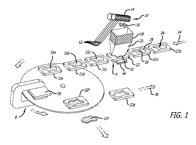
[009171 FIG. I i.0!..0,*Chematic representation of exemplary method iii
accordance with the
present invention.
1000181 FIG. 2 is a top view of an exemplary preform made according to the
exemplary method
shown in FIG. 1.
1000191 FIG. 3 is a side view of the exemplary preform shown in FIG. 2
DETAILED DESCRIPTION OF THE INVENTION
[000201 The present invention involves the use of composite chips in a method
for directly
forming preforms from the composite chips. The composite chips that are used
as the feed material
are the same or similar to the type of LTD chips typically used to make DFC
sheet molding
compound. Such UD chips contain UD fiber tows and an uncured thermosetting
resin as the
matrix_ Any of the LTD chips that are suitable for use in making DFC sheet
molding compound,
such as HexMC , may also be used as the composite chips that are directly made
into a preform
using the method of the present invention.
1000211 An exemplary method is set forth in FIG. 1. The initial step 10
involves making non-
agglomerating composite chips 16. The non-a.gglomerating composite chips 1.6
each includes
fibers and an uncured thermosetting resin. The non-agglomerating eo.mposite
chip.s 16 are kept at
a. temperature such that the tackiness of the uncured thermosetting resin is
sufficiently low to
prevent agglomeration of the composite chips. As shown at 10, multiple
parallel LTD tapes 12,
which are formed by slitting a sheet of .I.JD fibers, are fed to cutters 14.
The temperature of the
LTD tapes 12 is also sufficiently low that the uncured resin is not tacky. The
cutters 14 chop the
tack-free LTD tape 12 into multiple non-agglomerating composite chips 16. The
uncured
thermosetting resin in the non-agglomerating composite chips 16 remains tack-
free provided that
the temperature is kept at or below .the tack-free temperature (TO of the
resin_ Heating of the
-5-
CA 02982993 2017-10-16
WO 2016/182694 PCT/US2016/028035
Uncured tesitt1-0=:a temperature .abOVe TiftanstS the uncured resin to heroine
taCkyaint resnitg:in
..aggionieration of the chips:
[90022i It; is:< pre.,LiTed That that the LtD tape 11 be kept at temperatures
belt,iw ing
chopping to. form the non-agglomerating chips in order to eliminate problems
associated with
chopping tape Cutgaining tacky rosin. However, if. desired, it is possible to
chop the tape 12 into:
chips at temperatures above. ih and then cool the chips to below Ttf in order
to form the non-
agglomerating. composite chips
1000231 The fibers used to make the -LTD tape may be any of the fibers that
are typically
combined with thermosetting resins to form molding compounds or preforms. For
example, the
fibers may be carbon, glass, aramid or ceramic. The preferred fibers are
carbon tows that are
arranged unidirectionally in the UD tape 12. Carbon fiber tows are
commercially available, for
example, from Hexcel Corporation (Dublin, CA) under the trade name HexTow .
The following
are exemplary types of llexTowe that may be used to make the T.JD tape: AS2C
3K is a 3,000
filament carbon fiber tow weighing 0.200 gum and having a density of 1.80
glcm3; 2) AS4 3K is a
3,000 filament carbon fiber tow weighing 0.210 gint and having a density of
1.79 gm% 3) AS4
6K is a 6,000 filament carbon fiber tow weighing 0.427 gum and having a
density of 1.79 glcm3;
4) AS4 carbon 12K is a 12,000 filament carbon fiber tow weighing 0.858 g/m and
having a density
of 1.79 gm3.., 5) AS4C 3K is a 3,000 filament carbon fiber tow weighing 0.200
Wm and having a
density of 1.78 glem3; 6) AS4C 6K is a 6,000 filament carbon fiber tow
weighing 0.400 glm and
haying a density of 1.78 gni); 7) AS4C 12K is a 12,000 filament carbon fiber
tow weighing 0.800
gum and having a density of 1.80 glem3; 8) AS4D 12K is a 12,000 filament
carbon fiber tow
weighing (I.765 gin and having a density of 1.79 gni3; 9) AS7 12K is a 12,000
filament carbon
fiber tow weighing 0.800 gum and having a density of 180 glcin3; 10) IN12.A 6K
is a 6,000 filament
carbon fiber tow weighing 0.223 On and haying a density of 1.78 pri3; 11) IM2A
12K is a
12,000 filament carbon fiber tow weighing 0.446 g/m and having a density of
1.78 g/cm3; 12)
IM2C, 12K is a 12,000 filament carbon fiber tow weighing 0.446g/in and having
a density of 1.78
grd% 13) 1M6 12K is a 12,000 filament carbon fiber tow weighing 0.446 gm and
having a density
of 1.78 glcm3; 14) 1M7 6K is a 6,000 filament carbon fiber tow weighing 0123
glm and haying a
density of 1.78 gin3; 15) IM7 12K is a 12,000 filament carbon fiber tow
weighing 0.446 glin and
having a density of 1.78 glcm3; 16) AS4D 12K is a 12,000 filament carbon fiber
tow weighing
0.446 gm and having a density of 1.79 gni3; 17) 1M9 12K is a 12,000 filament
carbon fiber tow
-6-
CA 02982993 2017-10-16
WO 2016/182694 PCT/US2016/028035
weighing 0.315 iz?rn and havinga:Aen* of 1.86 giCiii3;: 16) Th410 12K is
A:t2,000 fi lamenteakon
fiber tow weighing 0,224 glm and having a. density of 1.7) gm3'
[(Kw 4! The invention is particularly useful in the. automotive indust.ttOie
LAO ainountg, 4
highly reproducible prOforms are teq*e.d. Preferred UD tape fibers for
:automotive applications
:include lar7e tow fibers,. sua as tlw.lsecoomintrig, 30,000 - 50,000
filaments.
[000251 The non-agglomerating composite chips 16 may be from 2 Mal to 2 cm
wide, 0.02 rnin
to 0.5 mm thick: and from 1 cm to 10 cm kmi. The size of the chips 16 will
depend upon the
desired chip density in the prepregõ the size of the prepreg and the
complexity of the three
dimensional shape of the prepreg. The composite chips 16 are preferably
rectangular in shape.
However other shapes are possible depending upon the angles at which the UD
tape is chopped.
For denser chip packing in the prepreg, smaller chips are preferred. The
smaller chip sizes are
also preferred when making preforms that have complex three dimensional
shapes.
[000261 Although the fibers are preferably in the form of a LTD tape 12, it is
possible to employ
other fiber orientations to form a tape where the fibers are not
unidirectional. There may be certain
applications where woven fiber may be used in place of LTD fibers. This
presents some benefits
for certain applications where impact resistance is important.
[000271 The uncured resin present in the UD tape 12 can be any of the uncured
thermosetting
resins that are combined with fibers to form molding compounds or preforms The
uncured resin
inherently causes the exposed surfaces of the composite chips 16 to be tacky
at temperatures above
Id- where they exhibit a degree of tack that is typically sufficient to cause
the composite chips 16
to stick together or agglomerate. The degree of tack is the same as that
required for chips used in
forming, DFC. sheet molding compound. However, it is important that the
initial temperature of
the chips 16 be maintained below Ttf in order to prevent premature
agglomeration of the chips
1000281 Although any number of inherently tacky uncured thermosetting resins
may be used in
the UD tape, epoxy resins are preferred. The tacky uncured thermosetting resin
includes one or
more epoxy resins and a curative for the epoxy resin(s). One or more resin
modifiers may be
added provided that the tackiness of the tacky uncured thermosetting resin is
not reduced to a level
below which cohesive preform formation is 1101 possible. The uncured
thermosetting resin should
make up from 30 to 70 weight percent of the 'JD tape 12 arid the non-
agglomerating composite
chips 16 with the remainder being LTD fibers. Any of the commercially
available epoxy resin
formulations that are tacky at room temperature or slightly below room
temperature are preferred
for use as the uncured thermosetting resin.
_7_
CA 02982993 2017-10-16
WO 2016/182694 PCT/US2016/028035
1000291 Exemplary ............................................................
epokyiesi*iitellide any Of the ditimdional attaidt:multifunctiOnal epoxy
:resins typically used in making prepreg. Examples of suitable difunctional
epoxy resins includa:
those based or 7 diglycidyl ether of Bisphencil F. Bisphonoi A (optimally brom
/I lteCD , glyeidyt
eihe.
f phenol-aldelyde adducts, glycidyl ethers of alipharik.:. (Lois. diglycidyl
ether, dieihylene
glycol diglycidyl ether, SEpikotet. Eporte, aromatic epoxy resins.epoxidised
oleims.. brominated
resins, ::aromatic glycidyl amines, heterocyclic glycidyl imidines and amides,
glycidvl ethers,.
fluorinated epoxylesingõor any.tonibination thereof. The difiinctional epoxy
in is preferably
:.3elected from diglycidyl ether of Bisphenol F, diglycidyl ether of Bisphenol
A, diglycidyl
dihydroxy naphthalene, or any combination thereof For example, diglycid1,4
ether of Bisphenol
F is available commercially from Huntsman Advanced Materials (Brewster, NY)
under the hade
names Araldite GY281 and GY285. A &functional epoxy resin may be used alone or
in any
suitable combination with other diftinctional epoxies or multifunctional
epoxies.
1000301
Multifunctional epoxy resins are typically trifunctional or tetrafinictional.
Suitable
multifunctional epoxy resins, by way of example, include those based upon:
phenol and cresol
epoxy novolacs, glycidyl ethers of phenol-aldelyde adducts; glycidyl ethers of
thaliphatic diols;
diglycidyl ether; diethylene glycol diglycidI,TI ether; aromatic epox3.,
resins; thaliphatic triglycidyi
ethers, aliphatic polyglycidyl ethers; epoxithsed olefin ; brominated resins;
aromatic glycidyl
amines; heterocyclic glycidyl imidines and amides; glycidyl ethers,
fluorinated epoxy resins or
any combination thereof.
[000311 Suitable trifunctional epoxy resins include those based upon: phenol
and cresol epoxy
novolacs; glycidyl ethers of phenol-aldelyde adducts; aromatic epoxy resins;
dialiphatic
triglycidyl ethers; aliphatic polyglyeidyl ethers; epoxidised olefins;
brominated resins, aromatic
glycidyl amines and glycidyl ethers; heterocyclic glycidyl imidines and
amides; glycidyl ethers;
fluorinated epoxy resins or any combination thereof Exemplary trifunctional
epoxy resin are
available commercially from Huntsman Advanced Materials (Monthey, Switzerland)
as Araldite
MY0500/0510 or Araldite MY0600/0610, and from Sumitomo Chemical Co, (Osaka,
Japan)
under the trade name ELM-120
[000321 Examples of suitable tetrafunctional epoxy resins include N,N,N1,M-
tetraglycidy1-4,4'-
diaminodiphenyl methane (TGDDM) available commercially as Araldite MY720 and
MY721
from Huntsman Advanced Materials (Mouthey, Switzerland), or ELM 434 from
Sumitomo.
-8-
CA 02982993 2017-10-16
WO 2016/182694 PCT/US2016/028035
[000331 The ettnitiVO: :that: is included With the :epOrf: resin to form the
tatty utittired
Ithelniosetting resin inay be any of the curatives and curative combinations
that are commonly used:
to cure epox,,.' 1:esins. C-frative,. as used herein, includes bath curing
vents and accelerators,
1000341 :ExempLil y k.-Aning, agents 'mein& pcoliwarboxylic anhydrides, such
as nadic anhydride
methylnadie: anhydride (MINA:
available from Aldrich)õ phthaic anhydrideõ
tetrahydrouhthalic anhydirde, heNahythopinhalic anhydride (EIHRA - available
from Anhydrides
and Chemicals Inc., Newark.:
methyltetrahydrophtLilic 3nitydrido (MTHPA - available from
Anhydrides and Chemicals Inc.), methylhexahydrophthalic anhydride (M1-11-1PA -
available from
Anhydrides and Chemicals Inc.), endomethylenetetiahydrophthalie anhydride,
hexachloroendomethylene-tetrahydrophthalic anhydride (Chlorentic Anhydride -
available from
Velsicol Chemical Corporation, Rosemont, Ill.), trimellitic anhydride:,
pyromellitic dianhydride,
maleic anhydride (MA - available from Aldrich), succinic anhydride (SA),
nonenylsuccinic
anhydride, dodecenyisuecinic anhydride (DDSA - available from Anhydrides and
Chemicals
polysebacic polyanhydride, and polyazelaic polvanhydride.
1000351 Further suitable curing agents are the amines, including aromatic
amines, e.g., 1,3-
diaminobenzene, I ,21-diaminobenzene, 4,4'-
diamino-diphenylmethane, and the
polyaminosulphones, such as 4,4'-diaminodiphenyl sulphone (4,46-DDS -
available from
Huntsman), 4-aminophenyl sulphone, and 3,3'- diaminodiphenyl sulphone (3õT-
DDS).
1000361 Also, suitable curing agents may include polyols, such as ethylene
glycol (E.G -
available from Aldrich), poly(propylene glycol), and poly(vinyi alcohol); and
the phenol-
formaldehyde resins, such as the phenol-formaldehyde resin having an average
molecular weight
of about 550-650, the p-t-butylphenol-fbrinaldehyde resin having an average
molecular weight of
about 600-700õ and the p-n-octylphenol-fonnaidelivde resin, having an average
molecular weight
of about 1200-1400, these being available as ITRJ 2210, 11R1-2255, and SP-
1068, respectively,
from Schenectady Chemicals, Inc., Schenectady, N.Y.). Further as to phenol-
formaldehyde resins,
a combination of CI U guanamineõ and phenol-fonnaldebyde resin having a
molecular weight of
398, which is commercially available as CG-i 25 from Ajinomoto USA Inc,
(Teaneck, N.J.), is
also suitable.
1000371 Different commercially available compositions may be present as curing
agent(s) in the
tacky uncured thermosetting resin. One such composition is AH-154, a
dicyandiamide type
formulation, available from Ajinomoto USA Inc. Others which are suitable
include Ancamide
400, which is a mixture of polyamide, diethyltriamine, and
tiethylenetetraamine. Ancamide 506,
-9-
CA 02982993 2017-10-16
WO 2016/182694 PCT/US2016/028035
which :of amiddomino, iiiiidazoline and -tetilettiyiertepenta.aminc, and
Abeamide
1284, which is a mixture of 44-mothylenediauiline and 1 ,3-b=enzenediamine;
these forinulatioli.
:are available front Pacific Afichor Chemical, Pe ti aemica1
on PrDducts<arid
Chemicals, Inc. õAllentown, P.
= = = =
[000381 Additional suitable curing agents include imittazole (I, 3-4iiaza.2, I-
cyclopentadiene)!
available from Sigma Aldrich T.St. Louis, Missouri),.2-=ethy1-4-
inettrOimidazole available from.
= Sigma Aldricivand boron trifluoride amine complexes..õ such as Anchor
1170, available from Air
Products & Chemicals, Inc.
1000391 Still additional suitable curing agents include 3,9-bis(3-aminopropy1-
2õ4,8,10-
tetroxaspiro[5.5]undecane, which is commercially available as ATU, from
Ajinomoto USA Inc.,
as well as aliphatic dihydrazide, which is commercially available as Ajicure
UDH, also from
Ajinomoto USA Inc., and mercapto-terminated pol),Tsidphide, which is
commercially available as
LP540, from Morton Lmernational, Inc., Chicago, Ill.
[000401 Exemplary accelerators that may be present as pan of the curative in
the tacky uncured.
thermosetting resin include any of the atone compounds that have been commonly
used as
accelerators, such as N,N-dimethyl.õ N'-3,4--dichlorphenyl urea (Diuron), N'-3-
ehlorophenyl urea
(Monuron)õ and N,N"-(1-methyl-m-phenylene bis[N',.V-=dimethyhirea] (e.g.Dyhard
UR500
available from Degussa),
[000411 Modifiers may be present in the tacky uncured thermosetting resin.
Exemplary
modifiers include -thermoplastic materials used to toughen the epoxy resin.
Such thermoplastics
may be soluble in the epoxy resin, such as polyether sulphone or
polyetherimide. Insoluble
thermoplastic particles, such as polyamide, polyamideimide and polyurethane,
may also be
included as a modifier.
1000421 Additional exemplary modifiers .that may be present in the tacky
uncured thermosetting
resin include flexibilizers, core shell rubbers, flame retardants, wetting
agents, pigments/dyes, UV
absorbers, anti-fungal compounds, fillers, conducting particles, and viscosity
modifiers. Suitable
fillers include, by way of example, any of the following either alone or in
combination: silica,
alumina. Titania, glass, calcium carbonate and calcium oxide_ The amount and
Type of modifier is
limited so that the inherently tacky nature of the tacky uncured thermosetting
resin is not
eliminated or reduced substantially.
-10-
CA 02982993 2017-10-16
WO 2016/182694 PCT/US2016/028035
[00043i For 'AtittlmortiVe application, which typically InV-ewe high
volumM:TelativeW fftgt
ouring.e=poxy reSitts Are preferred. Such resins typically include Bis A or
Bis F epoxy:tein as the
main ingredient 'with dicyandiamide being used as the principal curative..
[000441 The tack exhibited by theAurfaces of -the non-agglomerating composite
chips 16 cati
:incteased by increasing the temperature of the malted thermosetting, resitt.
Increasing the chip
temperature has a direct effect on the surface tack of chips. The surfaces of
composite chips
exhibit a.:bigher degree of tadt.::at higher temperatures and tend to exhibit
less tack when kept at
lower temperatures. The composite chips 16 are kept at an initial temperature
T1where the surfaces
of the composite chips are essentially tack-free so that the composite chips
16 do not agglomerate
when contacted with each other. A preliminary test to determine a suitable Ti
for a particular
uncured thermosetting resin may be accomplished by placing a group of the
composite chips 16
in a bag at the selected Ti and shaking it for a few (5-10) seconds. If
numerous agglomerates of
chips form, then the surfaces are exhibiting too much tack, The Ti is reduced
until only minor
amounts (less than 5 % by weight) of the chips form agglomerates during the
shake test.
[000451 Some heating of the composite chips 16 may occur during chopping and
handling. If
necessary the non-agglomerating chips 16 are cooled in cooling zone 18 to
ensure that they remain
at or below the tack-free temperature Ttf for a given thermosetting resin. At
Ttf, the tacky
composite chips 16 can be formed into a stream of non-agglomerating composite
chips. Ttf can
be preliminarily determined by placing a group of the cooled composite chips
in a bag and shaking
it for a few seconds. If any agglomerates of chips fomi, then the chips are
not cold enough to be
non-agglomerating and Ttf has not been reached. Ttf- is reached when the
cooled tacky composite
chips fail to agglomerate (less than 5% by weight agglomerate formation) when
shaken together
in a bag for a few seconds (5-10 seconds). It is preferred that the
temperature Ti of the composite
chips 16 he kept at a few degrees below `cif in order to ensure that the chips
do not agglomerate.
The temperature should not be so low that the uncured thermosetting resin
becomes powdery. For
many epoxy resins, the Ttf will range from 0 C to 25 C.
[000461 As an example, composite chips that include diglycidyl ether of
bisphenol A as the
epoxy resin and dicyandiamide as a curing agent are formed at a Ti of 10 C to
20 C in order to
provide non-agglomerating composite chips 16 that are at least a few degrees
below the Ttf for the
particular uncured epoxy resin. The chips 16 are cooled, if necessary, in
cooling zone 18 to
maintain the temperature of the composite chips 16 at the Ti of between 10 C.
to 20 C in order to
ensure that the composite chips 16 remain non-agglomerating. It is preferred
that the uncured
-11-
CA 02982993 2017-10-16
WO 2016/182694 PCT/US2016/028035
resin have a Ttf that is at 'Or close:46 the tenVitttlite, of the400tu (15t 16
25 C) in ::ordtT to
eliminate the need to expend el-ergy by keeping the chips refrigerated, it is
preferred that the
Orrupoite chips 16 be used immediately after they are fbruied. Plowever.õ the
chips l 6 may be
.,stored prior to use for relatively short periods of time (e.g. less than 24
hours) provided that the.
temperature. is kept at 01 below Ttt
[000471 The non-agglomerating composite clup$:: are. passed from the cooling
zone 18 intO, 4
fiume120 where they form a stream of non-agglomerating. composite chips. The
stream is directed
by funnel 20 into a preform tool 22 at filling station A. Apparatus, other
than a funnel, may be
used to direct the stream of non-agglomerating chips into the preform tool 22.
The chips 16 may
be randomly oriented as they pass through the funnel 20. The funnel 20 can
include vanes or other
internal structures that orient or align the chips 16 into a. desired
configuration as they pass through
the funnel 20
[000481 As indicated by arrow 24, the method is intended to be a mass
production method in
which multiple prefomi tools (e.g. 22a and 22b) are lined up for filing with
non-agglomerating
composite chips at filling station A. Multiple filling stations A may be used
so that the preform
tool 22 can be filled with more than one type of non-agglomerating composite
chip. The ability
to use multiple filling stations to form preforms that contain multiple types
of composite chips at
different locations and/or orientations within the preform is advantageous
when making complex
preforms that have complex performance requirements.
[000491 The preform tools include a cavity 26 that is formed by an interior
wall 28 and bottom
surface 30. The wall 28 and bottom surface 30 define and eventually form
exterior surfaces of the
final preform_ The stream of non-agglomerating composite chips is used to fill
the cavity 26 and
form a population of non-cohesive composite chips 32. II is preferred that the
preform tool 22 is
vibrated by a vibrator platform 34 in order to help settle and pack the non-
agglomerating
composite chips in the cavity 26 in order to control the distribution and
random orientation of the
non-cohesive composite chips. Preferably, the preform tool will be vibrated a
sufficient amount
to produce as uniform a top surface of the preform as possible. A vacuum may
be applied to the
cavity 26 in order to also help in controlling and/or maximizing the
distribution of the non-
agglomerating composite chips within the cavity 26. A scale (not shown) is
used to measure and
control the weight of non-agglomerating composite chips that are introduced
into the cavity. The
non-agglomerating composite chips form a population of non-cohesive composite
chips once they
-12-
CA 02982993 2017-10-16
WO 2016/182694 PCT/US2016/028035
are inside the
The use of scale onsureg:that the same amount. of chips are introduced into
each cavity, which in turn ensures the formation of preforms having unifOrm
dimensiOn*.
[000501 The tilled preform tools 22c, 224 and 22eõ which I-we filled with
populations of non-
cohesive composite chips 32e, 32.d and 32eõ revectively ace passed to a
consolidation station B.
The prefOrintbbig.are preferably allowed tnwarrn up toroom temperature during
the transfer from.
filling station A to consolidation station B or wade in station B. 'Room
temperature must be above
forthe.composite chips so that .the tack-free composite chips become tacky Or
sticky, hi effect,
the non-tacky uncured thermosetting resin present in the non-agglomerating
composite chips is
converted into a sticky uncured thermosetting .resin. The sticky uncured
thermosetting .resin is
formed by increasing the temperature and inherent stickiness of the non-sticky
uncured
thermosetting resin that is present in the population of non-cohesive
composite chips 32c, 32d and
32e
In consolidation station B, the population of non-cohesive composite chips are
formed by a
debulldng and consolidation apparatus 36 using heat and either vacuum or
pressure to form the
preform in as little .time as possible (e.g. a few seconds) The preform is
composed of a
consolidated population of cohesive composite chips.
[000511 It is preferred that the Tr for a particular composite chip be close
to the temperature of
the room in order to reduce the amount of energy that is needed to keep the
LTD tape 12 and
composite chips 16 cold enough for formation of a non-agglomerating stream of
composite chips.
For any given type of composite chips, it is preferred that the chips are
first tested, as discussed
above, to make sure that the chips agglomerate at the temperature of the room
in which the method
is carried out (e.g. 20 C). This insures that the temperature of the room
where the method is
carried out is acceptable for forming the preforms. The chips are then tested
at lower and lower
temperatures to determine the temperature Tff at which the tacky composite
chips become non-
agglomerating composite chips. This Tti is used as the preferred 7-1` because
it requires the
minimum.. amount of cooling in order to ensure that. the otherwise tacky
composite chips are non-
agglomerating composite chips. The difference between room temperature and the
preferred Ttf is
preferably on the order of FC to 10 C. It. should be noted that Li is an
inherent property of the
composite chip which is determined as set forth above, whereas Ti is the
chosen temperature at
which the composite chips are formed and introduced into the preform. Ti must
be equal to or
below Ttf.
[000521 The dehulking and consolidation apparatus 36 that is used to form the
preform is a
typical low pressure or vacuum mold apparatus that is used in forming sheet
molding compound
-13-
CA 02982993 2017-10-16
WO 2016/182694 PCT/US2016/028035
into a preform without:01ring the sticky uncured thermosetting regirt The
prefonia061,22 MUM
the bottom of apparatus 36 with the top MO thrilled by ate-usable vacuum bag
apparatus that
seals to the preform: tool or a plunger that applies pressure to the top of
the tacky composite Air*
Another option is to use a hard shell as the top which is sealed by a bladder
or hydraulic pressor&
a vacuum Or equivalent pressure of from 5 to 15 psi is applied to the paNt*
Attiring
consolidation to from the preform.
1000531 if desired, the preform can be "B-staged" while being present in
the debulking and
consolidation apparatus 36. B-staging is a kno-,VII wirtial curing procedure
that invoKeOwatrrig
the preform at. ambient pressure to a temperature of iihtexample 165'C
to:180'. for JUSt enough
time to substantially increase the viscosity of the sticky -uncured
thermosetting resin. Exemplary
B-staging times are on the order of 5 to 15 minutes al the 11-staging
temperature. The B,staged
preform is cooled to room temperature either *fore or after being removed from
the debulking
and consolidation apparatus 36.
[000541 The surface of the debulking and :consolidation apparatus :$6 and
surfaces of 140
preform tool 28 and 30 typically do not need :to be treated with a relent
agent. However,, if
desired, the surfaces may be treated with a release agent to ensure that the
preform does not stick
to these surfaces. Any release agent that is typically used on the surfaces of
preform tooling or
molds are suitable. Exemplary release agents include silicone-based release
agents and water-
based release agents. Tool surfaces coated with polytetrafluoroethylene or re-
useable release films
are also suitable.
1000551 After formation in debulking and consolidation apparatus 36, the
preform 32f is
removed from the preform tool 2211 The preform 32f may transferred for
immediate molding to
form the final part or it can be stored for molding at a later date_ As
represented by arrow 38, the
emptied preform tool 22g is recyckd back to filling station A for re-filling
and reuse to form
additional preforms.
[000561 Molding of the preform 32f is accomplished in the same manner as
molding of any
preform that contains fibers and an uncured tlermosettMg resin. Any of the
molding processes
that are used to mold preforms that contain DEC sheet molding compound may be
used for
molding of preform 12f. It is preferred that the preform 32f be compression
molded according to
known compression molding procedures for DEC sheet molding compound. For
example, the
preform is placed in a mold that is typically composed of two mold halves that
fomi a cavity that
matches the shape of the prefinm. Once in the mold, the preform is heated to
the curing
-14-
CA 02982993 2017-10-16
WO 2016/182694 PCT/US2016/028035
temperature of the sticky uncured thermosetting resin Arid molded :at high
passure to form the
.final part. Typical high-pressure curing temperatures for epoxy resins range
froml2O'C to 225')C
efened curing temperanires range from .120T. to 20C. Internal pressures within
the mold are.
preferably above 500 psi and below 2000 psi at the cure temperatures. Owe the
prqpreg has been
completely cured (typically 5 minutes to I hour at curing temperature), the
part. is removed from
the Mold and cooled to form the final part.
1000571 The above described exemplary method utilizes 'temperature to convert
the population
of non-cohesive composite chips into a preform thatis composed ofa. consOdated
poptdatio4 of
cohesive composite chips. In such a thermally based meilicA, it is necessary
that the uncured
thermosetting resin that is present in the non-agglomerating composite chips'
be: able to go from
being tack-free at T, which is preferably slightly belOW the room temperature,
to exhibiting tack
when heated up to the room temperature, which:is above Ttit A$:it moves to
consolidation Station
B. Thermosetting resins that cannot meet this criteria are not:suitable for
uge in this preferred
embodiment of the invention.
[000581 A bottom view of exemplary preform 32f is:sho\Nra in FIG. 2 KO:a:side
view is. shown
in FIG. 3. The preform 32f includes a top surface 40 that is formed during
debulking and
consolidation The preform 32f also has a side surface 42 that is defined and
formed by the wall
28 of the preform tool, The preform 32f further includes a bottomsurface 44
that is formed by
the bottom surface of the preform tool. The bottom surface 44 is contoured to
form three surface
sections 46, 48 and 50. The thickness of the preform 32f between surface
section 46 and top
surface 40 is "T". The thickness of the prefomi 32f between surface section 48
and top surface
40 is equal to T 318 XT. The thickness of the preform 32f between surface
section 50 and top
surface 4-0 is equal to T 3I8 5/8x T.
1000591 Preforms like 32f, which have contoured surfaces, can be made using
DFC sheet
molding compound. The DFC sheet molding compound can be used as a single ply
or multiple
plies to form a section of the preform having a thickness T. However, in
forming additional
sections of the preform that have fractional increases in thickness T, one
must consider using other
DFC sheet molding compounds that have different thicknesses and which must be
layered over
each other. The present invention avoids these issues associated with the use
of DFC sheet molding
compound to form contoured surfaces, like bottom surface 44, because the
composite chips are
used to directly till the pretbnn cavity rather than to form a sheet molding
compound that must
then be layered and formed into the preform.
-15-
CA 02982993 2017-10-16
WO 2016/182694 PCT/US2016/028035
[00060j In addition, if the partto.be -molded has sections that are thinner
than the DFC Sheet
molding compound, then the DEC. sheet molding compound must be compressed.
during melding
so that it flows to. form the thinner part. This type of material flow during
molding can have.
negative effects on the mechanical propertiestf the part and tends to increase
property variations
from part to part. The present invention- avoids this problem. because the non-
agglomerating chips
Can be formed directlyinto Very-Mit preform Sections that are nnickthinner
than the thickness of
a sheet of DFC molding.compound. The- thichiessof parts -made in accordance
with the. invention
is only limited by the thickness of the individual chips.
1000611 Having thus described exemplary embodiments of the present invention,
it should be
noted by those skilled in the art that the within disclosures are exemplary
only and that various
other alternatives, adaptations and modifications may be made within the scope
of the present
invention. Accordingly, the present invention is not limited by the above-
described embodiments,
but is only limited by the following claims.
-16-