Language selection

Search

Patent 2983959 Summary

Third-party information liability

Some of the information on this Web page has been provided by external sources. The Government of Canada is not responsible for the accuracy, reliability or currency of the information supplied by external sources. Users wishing to rely upon this information should consult directly with the source of the information. Content provided by external sources is not subject to official languages, privacy and accessibility requirements.

Claims and Abstract availability

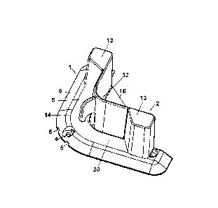
Any discrepancies in the text and image of the Claims and Abstract are due to differing posting times. Text of the Claims and Abstract are posted:

  • At the time the application is open to public inspection;
  • At the time of issue of the patent (grant).
(12) Patent Application: (11) CA 2983959
(54) English Title: REMOVABLE CHOCK
(54) French Title: AMORTISSEUR AMOVIBLE
Status: Deemed Abandoned and Beyond the Period of Reinstatement - Pending Response to Notice of Disregarded Communication
Bibliographic Data
Abstracts

English Abstract


A removable chock for securing coolers, storage bins, and tool boxes on boats,
and cargo
areas of vehicles and trailers and the like. The low-profile base mounts to
any flat
surface, and allows the chock to be installed and uninstalled from the base
without the
use of any tools. The chock can be removed from the base when not being used
and the
base remains installed. The low-profile design of the base greatly reduces the
potential
trip hazard, as well as offers an aesthetically pleasing appearance than a
permanently
installed chock.


Claims

Note: Claims are shown in the official language in which they were submitted.

CLAIMS
What is claimed is:
1. A removable chock assembly comprising:
a base having an inward side defining a first inside corner and a channel
formed
through said inward side;
a chock having a pair of vertical walls connected together and defining a
second
inside corner;
said chock further having a flange extending from said pair of vertical walls
in a
direction opposite of said second inside corner; and
said chock removably connected to said base with said chock disposed within
said
first inside corner and said flange disposed within said channel.
2. The removable chock assembly of claim 1, wherein:
said chock further comprising vertical ribs depending downwardly therefrom;
said base further comprising depressions formed through a top side of said
base;
and
wherein said vertical ribs are removably received by said depressions when
said
chock is removably connected to said base and prevent said flange from being
withdrawn
from said channel.
1

3. The removable chock assembly of claim 1, wherein said chock further
comprising an
elongated downward facing hook attached to said pair of vertical walls on a
side opposite
of said second inside corner.
4. The removable chock assembly of claim 1, wherein said base further
comprises drain
channels formed through a bottom side of said base.
5. The removable chock assembly of claim 1, wherein said chock further
comprises a
web extending between said pair of vertical walls and across said second
inside corner.
6. The removable chock assembly of claim 1, wherein said chock further
comprises
vertical columns extending adjacent to said pair of vertical walls, thereby
providing
rigidity to each vertical wall of said pair of vertical walls.
7. The removable chock assembly of claim 6, wherein:
said chock further comprising a vertical rib depending downwardly from each
vertical column;
said base further comprising depressions formed through a top side of said
base;
and
wherein said vertical ribs are removably received by said depressions when
said
chock is removably connected to said base and prevent said flange from being
withdrawn
from said channel.
2

8. The removable chock assembly of claim 1, wherein said base includes a
plurality of
holes extending therethrough for securing said base to a cargo surface using
mechanical
fasteners.
3

Description

Note: Descriptions are shown in the official language in which they were submitted.


REMOVABLE CHOCK
BACKGROUND OF THE INVENTION
[001] Devices that are currently used to secure items, such as coolers,
tool boxes, and
storage containers, are typically in the form of permanently mounted chocks.
[002] These devices are typically installed using multiple screws to attach
the chocks to
the floor or cargo surface. They are generally in the form of a large "L"
shaped
chock, whereas, 4 of them are installed on a flat surface strategically
located at the
4 outside corners of the item to be secured. Once installed, they are
permanent
and cannot be removed without removing the attachment screws, thereby
exposing multiple holes in the surface they were attached too. The chocks can
create a trip hazard, as well as become aesthetically unpleasing whenever the
stored item is removed.
[003] A solution to the problem would be a chock that is easily removable,
when not
being used.
1
CA 2983959 2017-10-27

SUMMARY OF THE INVENTION
[004] Embodiments of the present invention address this problem by
providing a two-
piece base and chock assembly, whereas the chock can be easily removed when
not being used to secure items. The base is L-shaped and has a very low
profile
and has provisions for the chock to be installed with interlocking features so
it
does not require the use of any tools. The base is first attached to the flat
surface
using multiple screws, but can also be installed by other means. The chock is
also
L-shaped. The chock is then installed to the base by simply sliding it into
the
channel provided in the base. The base and chock geometry is designed so that
the
two interlock and are held together without the use of any mechanical
fasteners.
Typically, a plurality of 4 embodiments are used at the location of the four
outer
corners of the item to be secured. When not in use, the chocks can be removed,
and the low-profile base is remaines attached to the flat surface, thereby
reducing
a potential trip hazard and is aesthetically pleasing.
2
CA 2983959 2017-10-27

BRIEF DESCRIPTION OF THE DRAWINGS
[005] The invention can be understood best by those with ordinary skill in
the art, with
reference to the following drawings, along with the detailed description:
[006] Figure 1 illustrates a top perspective view of the embodiment shown
assembled;
[007] Figure 2 illustrates an exploded top perspective view of the
embodiment;
[008] Figure 3 illustrates a bottom perspective view of the embodiment
shown
exploded;
[009] Figure 4 illustrates a bottom perspective view of the embodiment
shown
assembled;
[010] Figure 5 illustrates a top perspective view of the embodiment
including the
sectional cut planes for figures 6 and 7;
[011] Figure 6 illustrates a cross-sectional view taken along line 6 in
FIG. 5 with the
embodiment installed on a horizontal mounting surface;
[012] Figure 7 illustrates a cross-sectional view taken along line 7 in
FIG. 5 with the
embodiment installed on a horizontal mounting surface;
[013] Figure 8 illustrates the embodiments in one possible exemplary
configuration for
retaining a cooler; and
[014] Figure 9 illustrates the base embodiments with the chock embodiments
uninstalled.
3
CA 2983959 2017-10-27

DETAILED DESCRIPTION OF THE INVENTION
[015] Referring to the drawings, details of the embodiment will be
described herein.
[016] Referring to FIGS 1, 2 and 8, a plurality of the embodiment can be
installed to
help secure items, such as a cooler, tool box, or storage container 17 on a
horizontal surface 16, such as a boat deck, vehicle or trailer cargo bed. The
embodiment consists of a base 1 and a chock 2. First, the base 1 is installed
on a
horizontal surface 16 (specifics will be further explained later) then the
chock 2
can be inserted into the base 1 allowing a means of retaining items, such as a
cooler or storage container 17, in place on a horizontal surface 16.
[017] The base 1 has a low-profile surface 8 and a beveled edge surface 6
(see FIGS. 5,
6 and 7) and are intended to allow the base 1 from being an obstruction when
the
chock 2 is not installed (see FIG. 9) thereby reducing the risk of a potential
trip
hazard, as one example. The base is generally L-shaped and includes a top side
20, a bottom side 22, an outward side 24, an inward side 26, and interior
(inside)
corner 28, and an exterior corner 30.
[018] The base 1 has multiple mounting holes 4 (see FIGS. 2 and 3) for
attaching to a
horizontal surface 16, such as a boat deck or cargo bed. Mechanical fasteners
15
can be inserted through the mounting holes 4 and into the desired mounting
surface 16 (see FIGS. 6 and 7) but other means of attachment are possible,
without changing the spirit of the invention.
[019] The chock 2, is designed to be inserted into the base 1 without the
use of any
tools. Chock 2 has an extended horizontal flange 9 which is inserted into an
opposing channel 7 in the base 1. The flange 9 and channel 7 are designed to
4
CA 2983959 2017-10-27

interlock and retain the chock 2 with the base 1 together when the chock is
installed (see FIGS. 2, 3, 4, and 6)
[020] To further retain the base 1 and chock 2 from disengaging, recessed
depressions
3 in the base 1 and vertical ribs 11 on the chock 2 lock together when the
chock 2
is inserted into the base 1 (see FIGS. 5 and 7). Again, no tools are necessary
for
installing or uninstalling the chock 2 into the base 1.
[021] The chock 2 has two adjacent vertical surfaces (walls) 12 (see FIGS 2
and 8) that
are connected together and create an inside corner 32 for the purpose of
retaining
items in place. Column type shapes 13 are adjacent the ends of the chock 2
vertical wall surfaces 12 (see FIG. 2) which add rigidity to the vertical
surfaces,
but are not required for the spirit of the invention.
[022] The chock 2 also has a hook feature 14 (see FIGS 1, 6, and 8)
extending from the
intersection of the adjacent vertical wall surfaces 12, allowing an additional
means for securing the stored item by attaching a tie down, such as a bungee
cord
of rope and the like.
[023] The base 1 has longitudinal channels 5 (see FIGS. 2 and 3) located
underside
extending from the interior corner 28 to the exterior corner 30, thereby
allowing
water, or other liquids, to drain and not be trapped in the channel 7.
[024] The chock 2 also has a horizontal web surface 10, joining the bottom
of the
vertical wall surfaces 12 further adding further rigidity to the chock.
[025] The embodiments of the present invention have been described.
Nevertheless, it
will be understood that various modifications may be made without departing
from the spirit and scope of the invention.
CA 2983959 2017-10-27

Representative Drawing
A single figure which represents the drawing illustrating the invention.
Administrative Status

2024-08-01:As part of the Next Generation Patents (NGP) transition, the Canadian Patents Database (CPD) now contains a more detailed Event History, which replicates the Event Log of our new back-office solution.

Please note that "Inactive:" events refers to events no longer in use in our new back-office solution.

For a clearer understanding of the status of the application/patent presented on this page, the site Disclaimer , as well as the definitions for Patent , Event History , Maintenance Fee  and Payment History  should be consulted.

Event History

Description Date
Application Not Reinstated by Deadline 2021-08-31
Time Limit for Reversal Expired 2021-08-31
Inactive: COVID 19 Update DDT19/20 Reinstatement Period End Date 2021-03-13
Letter Sent 2020-11-16
Deemed Abandoned - Failure to Respond to Maintenance Fee Notice 2020-08-31
Inactive: COVID 19 - Deadline extended 2020-08-19
Inactive: COVID 19 - Deadline extended 2020-08-06
Inactive: COVID 19 - Deadline extended 2020-07-16
Inactive: COVID 19 - Deadline extended 2020-07-02
Inactive: COVID 19 - Deadline extended 2020-06-10
Inactive: COVID 19 - Deadline extended 2020-05-28
Inactive: COVID 19 - Deadline extended 2020-05-14
Inactive: COVID 19 - Deadline extended 2020-04-28
Letter Sent 2019-11-15
Common Representative Appointed 2019-10-30
Application Published (Open to Public Inspection) 2019-05-15
Inactive: Cover page published 2019-05-14
Inactive: Correspondence - Formalities 2017-12-05
Filing Requirements Determined Compliant 2017-11-29
Inactive: Filing certificate - No RFE (bilingual) 2017-11-29
Reinstatement Requirements Deemed Compliant for All Abandonment Reasons 2017-11-23
Small Entity Declaration Determined Compliant 2017-11-15
Inactive: Correspondence - Formalities 2017-11-15
Inactive: IPC assigned 2017-11-06
Inactive: First IPC assigned 2017-11-06
Inactive: IPC assigned 2017-11-06
Inactive: Office letter 2017-11-02
Application Received - Regular National 2017-11-02

Abandonment History

Abandonment Date Reason Reinstatement Date
2020-08-31

Fee History

Fee Type Anniversary Year Due Date Paid Date
Application fee - small 2017-11-15
Owners on Record

Note: Records showing the ownership history in alphabetical order.

Current Owners on Record
JEFFREY BRAWNER
Past Owners on Record
None
Past Owners that do not appear in the "Owners on Record" listing will appear in other documentation within the application.
Documents

To view selected files, please enter reCAPTCHA code :


To view images, click a link in the Document Description column. To download the documents, select one or more checkboxes in the first column and then click the "Download Selected in PDF format (Zip Archive)" or the "Download Selected as Single PDF" button.

List of published and non-published patent-specific documents on the CPD .

If you have any difficulty accessing content, you can call the Client Service Centre at 1-866-997-1936 or send them an e-mail at CIPO Client Service Centre.


Document
Description 
Date
(yyyy-mm-dd) 
Number of pages   Size of Image (KB) 
Description 2017-10-27 5 135
Drawings 2017-10-27 5 88
Claims 2017-10-27 3 51
Abstract 2017-12-05 1 13
Representative drawing 2019-04-09 1 6
Cover Page 2019-04-09 2 33
Filing Certificate 2017-11-29 1 201
Notice: Maintenance Fee Reminder 2019-08-19 1 120
Commissioner's Notice - Maintenance Fee for a Patent Application Not Paid 2019-12-27 1 533
Courtesy - Abandonment Letter (Maintenance Fee) 2020-09-21 1 552
Commissioner's Notice - Maintenance Fee for a Patent Application Not Paid 2020-12-29 1 536
Courtesy - Office Letter 2017-11-02 2 64
Correspondence related to formalities 2017-11-15 3 61
Courtesy Letter 2017-11-23 2 74
Courtesy - Office Letter 2017-10-27 4 86
Correspondence related to formalities 2017-12-05 2 32