Note: Descriptions are shown in the official language in which they were submitted.
CA 02983976 2017-10-25
WO 2017/021265
PCT/EP2016/067970
Method and device for determining a deterioration state in a suspension member
for
an elevator
The present invention relates to a method and to a device for determining a
deterioration
state, particularly a deterioration state of a load bearing capacity, in a
suspension member
arrangement for an elevator.
Elevators typically comprise a cabin and, optionally, a counterweight which
may be
displaced for example within an elevator shaft to different levels in order to
transport
persons or items for example to various floors within a building. In a common
type of
elevator, the cabin and/or the counterweight are supported by a suspension
member
arrangement comprising one or more suspension members. Suspension members are
sometimes also referred to as suspension traction members or suspension
traction media
(STM). A suspension member may be a member which may carry heavy loads in a
tension direction and which may be bent in a direction transverse to the
tension direction.
For example, a suspension member may be a rope or a belt. Typically,
suspension
members comprise a plurality of cords. The cords may be made for example with
a metal
such as steel.
During operation of the elevator, suspension members have to carry high loads
and are
typically repeatedly bent when running along for example a traction sheave, a
pulley, a
deflection sheave or other types of sheaves. Accordingly, substantial stress
is applied to
the suspension member arrangement during operation.
However, as elevators may typically be used by people for transportation along
very
significant heights, very high security requirements have to be fulfilled. For
example, it
has to be safeguarded that the suspension member arrangement can always
guarantee safe
support of the cabin and/or the counterweight. For such purposes, safety
regulations rule
that any substantial deterioration of an initial load bearing capacity of a
suspension
member arrangement can be detected such that for example counter-measures such
as
replacing a faulty suspension member from the suspension member arrangement
may be
initiated.
Generally, a load bearing capacity of a suspension member may be specified
when
designing the suspension member and may then be physically tested upon
completion of
the fabrication of the suspension member. Physical tests may comprise for
example
CA 02983976 2017-10-25
WO 2017/021265
PCT/EP2016/067970
- 2 -
tensile loading of the suspension member and measuring the suspension member's
reaction to an application of high tensile forces.
However, during actual operation of the elevator, it may be difficult or even
impossible to
perform such physical tests. With conventional steel ropes serving as
suspension
members, visual checking of a rope condition has been possible. However, in
modern
suspension members, load bearing cords are typically enclosed in a coating or
matrix and
are therefore not visible from outside. Therefore, alternative approaches for
determining a
load bearing capacity in a suspension member arrangement or determining
parameters
related thereto have been developed.
For example, elevator load bearing member wear and failure detection has been
described
in EP 1 730 066 Bl. A method and apparatus for detecting elevator rope
degradation
using electrical resistance is described in US 7,123,030 B2. Electrical signal
application
strategies for monitoring a condition of an elevator load bearing member are
described in
US 2011/0284331 Al and US 8 424 653 B2. Electrical signal application
strategies for
monitoring a condition of an elevator load bearing member are described in US
2008/0223668 Al and US 8 011 479 B2. A simplified resistance based belt type
suspension inspection is disclosed in US 2013/0207668 Al. An elevator system
belt type
suspension having connecting devices attached thereto is described in WO
2011/098847
Al. A method for detection of wear or failure in a load bearing member of an
elevator is
described in WO 2013/135285 Al. Electrical signal application strategies for
monitoring
a condition of an elevator load bearing member are described in EP 1 732 837
Bl.
"Health Monitoring for Coated Steel Belts in an Elevator System" have been
described in
a research article of Huaming Lei et al. in the Journal of Sensors, Volume
2012, Article
ID 750261, 5 pages, doi: 10.1155/2012/750261. WO 2013/119,203 Al discloses
wear
detection for a coated belt or rope, but does not consider bending cycles as
such or a
measurement thereof. The disclosure of all these documents shall be
incorporated herein
by reference.
Further alternative approaches for detecting a deterioration state in a
suspension member
arrangement have been proposed by the applicant of the present application in
earlier
patent applications US 62/199,375, US 14/814,558, EP 16 155 357 Al and EP 16
155
358 Al, all of which shall also be incorporated herein by reference. In these
specific
approaches, while electrical characteristics of suspension members and the
cords
comprised therein are determined, it is not necessary to specifically measure
any
electrical resistances in the cords or any magnitude of electrical currents
through the
cords but, instead, it may be enabled to obtain information about the
electrical
a
CA 02983976 2017-10-25
WO 2017/021265
PCT/EP2016/067970
- 3 -
characteristics of the suspension member by correlating for example various
electrical
measurements and interpreting results from such relative correlation. In other
words, in
these approaches it may not be necessary to have any detailed knowledge about
absolute
resistance values or current values but it may be sufficient to correlate
various electrical
measurements in order to obtain valuable information about electrical
characteristics in
the suspension member which allow determining information about the
deterioration state
of such suspension member.
In another alternative approach, a deterioration state of a suspension member
is not
detected by measuring any physical parameters of the suspension member itself
but,
instead, it is assumed that the suspension member deteriorates over time
mainly due to
wear occurring as a result of bending the suspension member. Such approach is
for
example described in WO 2010/007112 Al, the disclosure of which shall be
incorporated
herein by reference.
There may be a need for an alternative method and device for determining a
deterioration
state in a suspension member arrangement for an elevator. Particularly, there
may be a
need for such method and device which enable fulfilling high safety
requirements, simple
implementation and/or low cost.
Such needs may be met with the subject-matter of the independent claims.
Beneficial
embodiments are defined in the dependent claims and in the following
specification.
A first aspect of the present invention relates to a method for determining a
deterioration
state in a suspension member arrangement for an elevator. The suspension
member
arrangement comprises at least one suspension member comprising a plurality of
electrically conductive cords. The method comprises at least the following
steps:
- counting a number of bending cycles applied to the suspension member;
- determining an electrical characteristic of the suspension member;
- performing
(a) determining a critical deterioration state upon monitoring both:
the counted number of bending cycles applied to the suspension member and
the determined electrical characteristic of the suspension member;
and/or
(b) determining an unexpected deterioration state based on deriving a current
actual
deterioration state of the suspension member based on the determined
electrical
characteristic and assuming a currently expected deterioration state based on
the counted
number of bending cycles and comparing the current actual deterioration state
with the
CA 02983976 2017-10-25
WO 2017/021265
PCT/EP2016/067970
- 4 -
currently expected deterioration state; and
- initiating a defined procedure upon the determining of at least one of the
critical
deterioration state and the unexpected deterioration state.
Without restricting the scope of the invention in any way, ideas underlying
embodiments
of the invention may be understood as being based, inter alia, on the
following
recognitions and observations:
On the one hand, in conventional approaches for detecting a deterioration
state of a load
bearing capacity in a suspension member arrangement such as some of those
approaches
indicated in the above introductory portion, electrical characteristics of
cords included in
a suspension member have been taken as indicators for changes in the
deterioration state
of the suspension member. In some of the prior art approaches, electrical
resistances or
other electrical characteristics within the cords have been measured and it
has been
assumed that an increase of such electrical resistances correlates to a
deterioration of the
load bearing capacity of the suspension member.
However, it has been found that it may be very difficult or even impossible to
define
sufficiently precise quantitative indicators for a critical or unexpected
deterioration state
of a suspension member based only on measuring electrical characteristics in
the
suspension member. For example, wear, fatigue phenomena and/or corrosion may
slowly
deteriorate the suspension member and particularly its load bearing capacity.
It has been
found that particularly deteriorations of the suspension member due to such
slowly acting
effects may be very difficult to be detected. While it is assumed that such
effects may
alter for example electrical resistances through the cords of the suspension
member, it is
hardly possible to determine any unambiguous indicators such as for example
maximum
electrical resistance values which, when being exceeded, would necessarily
indicate
excessive deterioration of the suspension member.
On the other hand, alternative approaches for determining the deterioration
state of the
suspension member only based on counting specific deteriorating events such as
counting
bendings of the suspension member may also be assumed as being insufficient
for
unambiguously indicating excessive deterioration of the suspension member.
This is
particularly true as such approaches mainly rely on wear and deterioration
experiments
performed under specific conditions.
For example, using a new suspension member directly after its fabrication,
experiments
have been performed in which the suspension member was put under substantial
mechanical stress by repeated bending thereof and it was then tested after
which number
CA 02983976 2017-10-25
WO 2017/021265
PCT/EP2016/067970
- 5 -
of bendings the suspension member loses for example 20% or 40% of its initial
load
bearing capacity, such loss being assumed as an excessive deterioration. Based
on such
experiments, it is then assumed that the suspension member may be bent at
least a
specific number of times before being excessively deteriorated such that it
needs to be for
example replaced.
However, as these experiments are generally performed under specific
conditions in
which it is assumed, on the one hand, that the suspension member in its
initial state is not
deteriorated and in which is furthermore assumed, on the other hand, that
deteriorations
within the suspension member mainly occur due to repeated bending thereof,
such
approaches for determining deteriorations may generally ignore other
influences which
also may deteriorate the quality of the suspension member.
For example, incorrect handling of the suspension member during e.g. transport
from a
fabrication site to an installation site and/or during installation of the
suspension member
at the installation site may harm the integrity of the suspension member. For
example, a
belt serving as a suspension member may be damaged during transportation or
installation such that its polymer jacket enclosing its cords is damaged. Due
to such
damage, the cords may for example be exposed, i.e. be no more protected by the
jacket,
such that e.g. local corrosion of the exposed cords may significantly
deteriorate the
quality of the belt.
In other words, it has been found that both conventional approaches, i.e. the
measuring of
electrical characteristics as well as the counting of bendings of the
suspension member,
when taken as a single measure may not reliably indicate excessive
deterioration of the
suspension member.
It is therefore proposed herein to combine these conventional approaches in
order to
provide for a more reliable method for determining a deterioration state in a
suspension
member arrangement. Therein, the number of bending cycles applied to the
suspension
member is counted as one measure and, additionally as another measure,
electrical
characteristics of the suspension member are determined.
A critical deterioration state may then be determined for example when either
the counted
number of bending cycles exceeds a specific allowable maximum number of
bending
cycles or the measured electrical characteristics deviate from reference
characteristics by
more than an allowable maximum deviation.
=
CA 02983976 2017-10-25
WO 2017/021265
PCT/EP2016/067970
- 6 -
Alternatively or additionally, an unexpected deterioration state may be
determined by, on
the one hand, deriving a current actual deterioration state of the suspension
member based
on the determined electrical characteristic(s) and, on the other hand,
assuming a currently
expected deterioration state based on the counted number of bending cycles
and, finally,
comparing the current actual deterioration state with the currently expected
deterioration
state. In other word it is verified whether or not the currently measured
electrical
characteristics of the suspension member indicate an actual deterioration
state with
conforms to an expected deterioration state as it may be assumed due to the
counted
number of bendings (i.e. the "operational age") of the suspension member.
Upon the determining the critical deterioration state and/or the unexpected
deterioration
state, an adequate defined procedure may be initiated such as e.g. stopping
operation of
the elevator, adequately modifying its operation, and/or informing a third
party regarding
the critical deterioration state and/or the unexpected deterioration state.
In other words, two generally independent indicators are monitored for finally
determining whether the suspension member is excessively and/or unexpectedly
deteriorated or not in order to then enable initiating suitable measures such
as stopping an
operation of the elevator and/or replacing the suspension member and/or
providing
relevant information to the operator or to servicing/maintenance staff of the
elevator.
In such combined approach, it may be assumed, on the one hand, that a
deterioration of
the suspension member is mainly affected by repeated bending thereof. Thus, by
counting
the bending cycles and comparing e.g. with an allowable maximum number of
bending
cycles which has previously be determined based on for example intensive
experimentation, a well-defined criterion for distinguishing between
acceptable
deteriorations and excessive deteriorations of the suspension member may be
provided.
However, in the combined approach proposed herein, it is also taken into
account that
such assumption is generally only true as long as the suspension member is
correctly
handled and operated and is not, for example, damaged by other effects than
the repeated
bending thereof. Therefore, in order to also enable accounting for such
additional
deteriorating effects, electrical characteristics of the suspension member are
also
determined or measured and are additionally taken into account as an
additional indicator
for an excessive deterioration of the suspension member. As described in
further detail
below, such electrical characteristics may provide for reliable indicators
indicating
various types of damages to the suspension member all of which may immediately
reduce
6 1
4
CA 02983976 2017-10-25
WO 2017/021265
PCT/EP2016/067970
- 7 -
for example a load bearing capacity of the suspension member or at least
reduce a life
cycle of the suspension member.
In other words, in the combined approach proposed herein, no or only an
acceptable
deterioration of the suspension member is generally assumed as long as the
number of
bending cycles applied to the suspension member does not exceed the allowable
maximum number. However, this is only true as long as the electrical
characteristics of
the suspension member measured generally simultaneously with counting the
bending
cycles indicate that no specific damages or specific deteriorations occurred
at the
suspension member. If, however, such specific damages or a specific
deteriorations are
detected based on the electrical measurements, they may be taken as indicating
excessive
or unexpected deteriorations of the suspension member or, alternatively, they
may be
taken as at least influencing the deterioration state of the suspension member
such that,
for example, the allowable maximum number of bending cycles may be adapted or
corrected to a lower value.
Accordingly, using the combined approach proposed herein, a reliability in
determining
an excessive deterioration state in a suspension member may be significantly
improved in
comparison to applying each single approach alone. Furthermore, synergy
effects may
occur upon combining the two prior art approaches thereby possibly further
increasing an
operation safety of the elevator and/or allowing economical benefits.
According to an embodiment of the present invention, the allowable maximum
deviation
about which the currently determined electrical characteristics are allowed to
deviate
from reference characteristics is determined taking into account the counted
number of
bending cycles applied to the suspension member.
In other words, the allowable maximum deviation about which the currently
measured
electrical characteristics may deviate from reference characteristics before
being
interpreted as indicating a critical deterioration state may not necessarily
be a fixed
number or parameter. Instead, such allowable maximum deviation may be
determined
taking into account how often the suspension member has already been bent,
i.e. taking
into account characteristics of the suspension member relating to its
operational "age".
For example, measuring specific electrical characteristics for a relatively
novel
suspension member which has not yet significantly deteriorated due to repeated
bending
thereof may be interpreted as not yet indicating any critical deterioration
state whereas
measuring the same specific electrical characteristics for an old suspension
member
which has already been bent many times and which is therefore already
significantly
CA 02983976 2017-10-25
WO 2017/021265
PCT/EP2016/067970
- 8 -
deteriorated and close to its end of life cycle may be interpreted as
indicating an actually
critical deterioration state for this old suspension member.
Accordingly, the two criteria for determining the critical deterioration state
of the
suspension member, i.e. the counted number of bending cycles and the currently
measured electrical characteristics, do not necessarily have to be
independently
interpreted from each other but, to the contrary, may inter-correlate.
Specifically, the
counted number of bendings of the suspension member may be taken into account
when
deciding whether or not a specific measured electrical characteristics shall
be interpreted
as indicating a critical deterioration state or not.
This may advantageously result in an extended usability of the suspension
member as, for
example, the decision whether or not a critical deterioration state is present
due to which,
for example, the suspension member has to be replaced may be made on the basis
of more
sophisticated indications. For example, slight deviations in the measured
electrical
characteristics of the suspension member at the beginning of its life-cycle
will not
necessarily result in obligating any replacement of the suspension member
whereas at a
later stage in the life-cycle the same electrical characteristics may be
interpreted as
indicating critical deteriorations necessitating immediate replacement of the
suspension
member.
Alternatively, according to an embodiment of the present invention, the
allowable
maximum deviation is fixedly predetermined.
In other words, the allowable maximum deviation about which currently measured
electrical characteristics may deviate from reference characteristics may be
fixedly set.
For example, such allowable maximum deviation may be derived from preceding
experimentations. For example, tests or experiments may show that specific
damages or
critical deteriorations of the suspension member typically come along with a
change in
electrical characteristics such that when currently measured electrical
characteristics of
the suspension member alter by such specific deviation this may interpreted as
indicating
that critical deterioration state.
Assuming fixedly predetermined allowable maximum deviations may be implemented
in
a simple manner such as for example storing corresponding deviation values in
a memory
comprised in a device adapted for performing the monitoring method proposed
herein.
)
CA 02983976 2017-10-25
WO 2017/021265
PCT/EP2016/067970
- 9 -
According to an embodiment of the present invention, the allowable maximum
number of
bending cycles is determined taking into account the currently determined
electrical
characteristics of the suspension member.
In other words, similarly to the embodiment explained further above, the two
determination criteria may be interpreted as influencing each other. In the
present case,
the allowable maximum number about which the suspension member may be bent
before
assuming its end of life due to excessive deterioration thereof may not be a
fix number
but, instead, may itself depend on currently measured electrical
characteristics of the
suspension member.
For example, when the measured electrical characteristics indicate that the
suspension
member is in a very good state although it is already rather old and has been
bent many
times, this information may be used to increase the allowable maximum number
of
bendings such that the suspension member is allowed to have a longer
operational life
than a suspension member for which the measured electrical characteristics
already
indicate some significant, but not yet critical, deteriorations.
Accordingly, the life-cycle of the suspension member may be adapted better to
its actual
deterioration conditions and suspension members may therefore potentially be
used for a
longer period of time without increasing a risk for failures.
Alternatively, according to an embodiment of the present invention, the
allowable
maximum number of bendings is fixedly predetermined.
Such fixedly predetermined maximum number may be derived for example from
preceding experiments or tests. The fixed number may be easily stored for
example in a
device's memory for subsequent repeated comparing with the currently counted
number
of bending cycles.
According to an embodiment of the present invention, the reference
characteristics to
which the currently determined electrical characteristics may be compared are
determined
based upon measuring electrical characteristics of the suspension member in a
non-
deteriorated condition.
In other words, when determining whether the measured electrical
characteristics indicate
a critical deterioration state of the suspension member, currently measured
electrical
characteristics shall be compared to reference electrical characteristics
which have been
measured in a state in which the suspension member was not deteriorated, i.e.
for
example directly after fabricating and testing the suspension member.
Accordingly, by
2
CA 02983976 2017-10-25
WO 2017/021265
PCT/EP2016/067970
- 10 -
comparing currently measured electrical characteristics with original
electrical
characteristics of the suspension member it may be determined whether or not
these
electrical characteristics have significantly altered and deviate from the
original electrical
characteristics by more than an allowable deviation. By specifically comparing
the
currently measured electrical characteristics with non-deteriorated
characteristics, it may
be determined for example whether the suspension member has been significantly
damaged e.g. during transportation, storage and/or installation thereof.
As used herein, the term bending cycles may be understood for example as
referring to a
process of bending at least a portion of the suspension member in a direction
transverse to
its longitudinal direction. For example, the suspension member is bent when
running
along a traction sheave or a pulley. One bending cycle may be interpreted as
resulting
from bending at least a portion the suspension member once into a bending
direction and
then bending it back Each back and forth bending generally significantly
stresses the
suspension member and induces wear effects.
According to an embodiment of the present invention, the suspension member is
subdivided into several sections and a number of section bending cycles
applied to each
section of the suspension member is counted for each of the sections. The
number of
bending cycles applied to the suspension member is then set to correspond to
the
maximum of all numbers of section bending cycles counted for each of the
sections of the
suspension member.
In other words, bending cycles of the suspension member are preferably not
simply
counted independent of a location where the suspension member is bent. To the
contrary,
the suspension member is assumed to be subdivided into a multiplicity of
sections and it
is then determined at which of the sections the suspension member has been
bent. The
bending cycles are counted for each of the sections separately. For example,
some
sections of the suspension member are bent more frequently during typical
operation of
the elevator than other sections. This may be due to e.g. the fact that an
elevator cabin is
moved more frequently to specific floors such as a ground floor than to other
locations.
The number of bending cycles taken as indicating whether or not a critical
deterioration
state has been reached is then not necessarily equal to the number of bendings
applied to
the suspension member in its entirety but shall correspond to the number of
bendings
applied to the section of the suspension member which has been bent most
frequently.
Accordingly, as the number of bendings applied to each one of the various
sections of the
suspension member is typically significantly lower than the overall number of
bendings
CA 02983976 2017-10-25
WO 2017/021265
PCT/EP2016/067970
- 11 -
applied to the entire suspension member, the life-cycle of the suspension
member may be
significantly extended while still providing for very high operational safety
as the critical
deterioration state of the suspension member may be determined as resulting
from its
"weakest section". I.e. the critical deterioration state of the suspension
member is
determined based on the counted number of bending cycles applied to the
section which
has been bent most frequently.
A similar approach has been described by the applicant of the present
application in
previous patent applications and/or patents WO 2010/007112 Al and EP 2 303 749
B1
which shall be incorporated herein in their entirety by reference. It shall be
specifically
noted that protection is or may be sought also for such features described in
these
previous applications and/or patents and that such features may contribute to
achieving
the technical aim of embodiments of the present invention and may thus be
comprised in
the solution of the technical problem underlying the invention which is the
subject of the
present application. Particularly, such features may implicitly clearly belong
to the
description of the invention contained in the present application as filed,
and thus to the
content of the application as filed. Such features are precisely defined and
identifiable
within the total technical information within the reference documents.
In a significantly simplified approach, the number of bending cycles applied
to the
suspension member may be set equal to a number of trips performed by the
elevator in
one motion direction before reversing the motion direction. It is then assumed
that during
each trip the suspension member is bent at least in some of its sections due
to e.g. being
guided along a traction sheave or pulley. The same sections may only be bent
again if the
motion direction of the elevator is reversed at a later point in time and the
sections are
guided again along the traction sheave of pulley. In other words, in such
simplified
approach, the number of bending cycles may be taken as being related to a
number of
times of reversal of the motion direction of the elevator during its
operation.
Such approach may be particularly easy to implement as many elevators comprise
a trip
counter such that the number of bendings of the suspension member may easily
be
assumed to correspond to the number of trips counted by the trip counter.
However, such
approach does not take into account that generally during each trip only some,
but not all,
of the sections of the suspension member will be bent. Accordingly, such
simplified
approach will generally result in assuming a critical deterioration state
earlier than with
the more sophisticated approach describe before.
CA 02983976 2017-10-25
WO 2017/021265
PCT/EP2016/067970
- 12 -
According to an embodiment of the present invention, the measuring of the
electrical
characteristics of the suspension member comprises at least one of:
- electrical measurements indicating that at least one cord in the suspension
member is broken;
- electrical measurements indicating that an electrical connection between a
voltage supply for applying the electrical voltage to the at least one of the
cords and the at
least one of the cords is interrupted;
- electrical measurements indicating that at least one cord in the suspension
member is electrically connected to ground;
- electrical measurements indicating that at least two cords in the suspension
member are shorted;
- electrical measurements indicating that an electrical conductivity through
at
least one of the cords of the suspension member changed over time.
In other words, the step of measuring electrical characteristics of the
suspension member
may comprise one or more of different types of electrical measurements, each
type
specifically relating to a specific type of deterioration or damage possibly
occurring
within a suspension member.
For example, electrical measurements may indicate that at least one of the
cords
comprised in the suspension member is broken. In such case, an electrical
connection
through the broken cord is generally interrupted which may be easily detected
e.g. by
applying an electrical test voltage to the cord at one end thereof and
detecting a resulting
voltage for example at the opposite end of the suspension member. One or more
broken
cords in a suspension member typically represent a severe deterioration of the
load
bearing capacity of the suspension member.
As a further example, electrical measurements may be used for testing whether
or not the
voltage supply for applying the electrical voltage to the at least one cord is
still correctly
connected to the respective cord or whether there is an electrical
interruption. While such
interruption may not necessarily indicate a critical deterioration of the load
bearing
capacity of the suspension member, it may still represent a critical
deterioration state for
the elevator as due to such interruption no meaningful measurements of
electrical
characteristics may be performed at the suspension member. Therefore,
detecting such
non-connected voltage supply or electrical interruption may be necessary for
securing the
safety of the elevator.
CA 02983976 2017-10-25
WO 2017/021265
PCT/EP2016/067970
- 13 -
As a third example, electrical measurements may indicate that at least one of
the cords
comprised in the suspension member is electrically connected to ground. Such
ground
connection may typically occur as a result of damages to the jacket enclosing
the cords.
Due to such damages, one or more cords may be locally exposed and may
therefore come
into contact for example with electrically grounded sheaves or pulleys or
other
components within an elevator arrangement. Accordingly, upon detecting any
electrical
grounding of one or more cords, it may be assumed that for example the jacket
of the
suspension member is damaged, such damage possibly immediately or over a
longer term
resulting in a deterioration of the suspension member.
As a fourth example, electrical measurements may indicate that at least two
cords in the
suspension member are electrically connected to each other, i.e. are shorted.
Such
electrical shorting may occur typically upon the isolating portions of the
jacket between
neighboring cords being damaged. Accordingly, detecting such electrical
shortings may
be taken as indicating damages of the jacket which may potentially result in a
deterioration of the suspension member.
As a final example, electrical measurements may indicate that an electrical
conductivity
through at least one of the cords comprised in the suspension member changed
over time,
i.e. does no more correspond to the electrical conductivity through the cords
in their
initial state. Such changes in electrical connectivity may result from changes
in other
physical characteristics of the cords such as general or local corrosion of
the cords.
Accordingly, changes in the electrical conductivity may indirectly indicate
changes in
these other physical characteristics which may then correlate to a critical
deterioration
state, particularly with a reduced load bearing capacity, of the suspension
member.
According to an embodiment of the present invention, the determining of
electrical
characteristics comprises at least one of
- determining an electrical resistivity through the suspension member,
- determining an electrical conductivity through the suspension member,
- determining an inductivity through the suspension member,
- determining electrical characteristics using magnetic measurements applied
to the
suspension member, and
- determining electrical characteristics using phase measurements applied to
the
suspension member.
For example, prior art approaches such as those mentioned in the introductory
portion
teach that a deterioration state of a suspension member may be at least
qualitatively or
r
i I CA 02983976 2017-10-25
WO 2017/021265
PCT/EP2016/067970
- 14 -
even quantitatively determined based upon measuring electrical resistances
through cords
of the suspension member. Accordingly, by for example measuring such
electrical
resistances, it may be determined whether a critical deterioration state
occurred at the
suspension member e.g. due to continuous wear such that e.g. the suspension
member
should be replaced even before an allowable number of bending cycles has been
reached.
Alternatively, by for example measuring such electrical resistances, it may be
verified
whether an expected deterioration state of the suspension member which is
assumed only
based on the operation age of the suspension member, i.e. the number of
bending cycles
applied thereto, corresponds to the actual deterioration state as derived from
the electrical
characteristics, i.e. in this case the measured electrical resistance.
According to an embodiment of the present invention, upon measuring the
electrical
characteristics, an electric indicator current 1õ correlating to a net sum of
all phases of a
multi-phase alternating current is measured, wherein at least one of the
phases of the
multi-phase alternating current is applied to one of the cords of the
suspension member.
According to a more specific embodiment of the present invention, the
measuring of
electrical characteristics of the suspension member comprises:
- providing a multi-phase alternating current circuitry including multiple
electrically
conductive legs;
- applying at least one phase of a multi-phase alternating current to at least
one of the
cords of the suspension member by being electrically connected to one of the
legs of the
multi-phase alternating current circuitry;
- applying at least one other phase of the multi-phase alternating current to
at least one of
another at least one cord of the suspension member and at least one separate
resistor
being electrically connected to at least one other leg of the multi-phase
alternating current
circuitry, wherein a peak current in each phase is shifted by a phase angle
with respect to
a peak current in another phase;
- measuring an electric indicator current 1õ being at least one of:
a net sum of all phases of the multi-phase alternating current and
an electric bypass current through a neutral wire being connected in
parallel to the multi-phase alternating current circuitry;
- determining the measured electrical characteristics of the suspension member
based on
the measured indicator electric current.
Briefly summarized and expressed in a simpler wording than in the claims, but
without
restricting the scope of the claims, an idea underlying this embodiment of the
inventive
method may be briefly summarized as follows: One or more of the cords of a
suspension
CA 02983976 2017-10-25
WO 2017/021265
PCT/EP2016/067970
- 15 -
member may be made part of a multi-phase alternating current circuitry by
connecting it
preferably in series with at least one of the legs of such multi-phase
alternating current
circuitry. Accordingly, at least one phase of a multi-phase alternating
current is directed
through this leg (or these legs) and therefore flows through the respective
cord(s). One or
more other phases of the same multi-phase alternating current are either
directed through
other cords of the same or other suspension members of the suspension member
arrangement or are directed through one or more separate resistors by
connecting these
other cords or separate resistors electrically to at least one other leg of
the multi-phase
alternating current circuitry. Therein, the term "resistor" may be interpreted
as
representing any type of electrical load including for example load with
electrical
impedance. In other words, at least one of the phases of the multi-phase
alternating
current flows through a portion of the suspension member arrangement by being
applied
to at least one of its cords whereas at least one other phase may also flow
through cords
of the suspension member arrangement or may be directed through separate
resistors. In
such multi-phase arrangement, the phases of the multi-phase alternating
current flow
through the various legs of the multi-phase alternating current circuitry with
a specific
phase relationship. Generally, physical characteristics of the suspension
member directly
result in changes in its electrical characteristics, i.e. changes in electro-
physical
characteristics of e.g. cords in the suspension member may result from e.g. a
change in
the diameter of the cords, from any shorts or shunts, from breaks, etc. In
case physical
characteristics of the suspension member and electrical characteristics
relating to such
physical characteristics change over time, the phase relationship in a multi-
phase
alternating current will generally change. The change in such phase
relationship may be
measured relatively easily. In one approach, such phase relationship change
may be
determined by measuring an electric indicator current resulting as a net sum
of all phases
of the multi-phase alternating current. Such net sum directly depends on the
phase
relationship between the various phases such that changes in the net sum
electric current
allow deriving information about the electrical characteristics and therefore
the
deterioration state of the load bearing capacity of the suspension member
arrangement.
Alternatively to measuring the net sum of all phases of the multi-phase
alternating
current, an electrical bypass current through a neutral wire being connected
in parallel to
the multi-phase alternating current circuitry may be measured. Such bypass
current
through the neutral wire directly depends on the various phase currents
flowing through
the legs of the multi-phase alternating current circuitry. Therefore, a change
in such
bypass current may also enable deriving information about the electrical
characteristics
and therefore the deterioration state of the load bearing capacity in the
suspension
CA 02983976 2017-10-25
WO 2017/021265
PCT/EP2016/067970
- 16 -
member arrangement. All these measurements do not require any direct or
indirect
measuring of resistances within the cords of a suspension member but it may be
sufficient
to measure an electric indicator current only.
Particularly, according to an embodiment, the deterioration state or the
electrical
characteristics relating to such deterioration state may be determined based
on a deviation
of the measured electric indicator current from a reference current value.
For example, an initial value of the measured indicator current may be
determined upon
installation of the suspension member arrangement in the elevator in a non-
deteriorated
state and such initial value can be taken as the reference current value.
Alternatively, such
reference current value may be determined based on other measurements,
calculations
and/or assumptions. During the operation of the elevator, the same or a
corresponding
indicator current may be measured with the multi-phase alternating current
circuitry
described herein. In case such subsequently measured indicator electric
current
substantially deviates from the reference current value, this may be taken as
indicating a
substantial deterioration in the load bearing capacity of the suspension
member.
Particularly, according to an embodiment, a critical deterioration state or
the electrical
characteristics relating to such deterioration state may be detected upon the
measured
electric indicator current deviating from the reference current value by more
than a
predetermined difference value.
In other words, a specific difference value may be predetermined. For example,
physical
tests may be made in order to obtain information on how electrical
characteristics of
cords in a suspension member change upon physical stress and current values
may be
determined based on such physical tests. From such preceding experiments, the
predetermined difference value may be derived such that, in later normal
operation of the
elevator, the electric indicator current being the indicator for the
deterioration state may
be repeatedly or continuously measured and a critical deterioration state may
be assumed
as soon as changes in this measured indicator current exceed the predetermined
difference
value. Upon detecting such critical deterioration state, counter-measures such
as for
example replacing the respective suspension member may be initiated.
According to an embodiment, the indicator current Iõ is measured using a
measuring
arrangement comprising a measuring device for contactless measuring of an
electrical
current in a conductor arrangement. The measuring device may be for example a
current
transformer or a Hall effect current sensor.
CA 02983976 2017-10-25
WO 2017/021265
PCT/EP2016/067970
- 17 -
One possible option for contactless measuring of an electrical current is
based on
induction. Every electrical current in a conductor arrangement creates a
magnetic field
and changes in the current result in variations in the magnetic field which
may then be
used for inductively coupling the conductor arrangement in which the
electrical current to
be measured flows with a conductor arrangement of the measuring device.
Contactless
measuring of an electrical current enables a very simple measurement. For
example, no
direct physical connection needs to exist between the measuring device and the
conductor
arrangement. Instead, the measuring device may be arranged slightly spaced
apart from
the conductor arrangement in which the electrical current to be measured flows
and/or
may be electrically isolated therefrom.
In a specific embodiment, the electrical current may be measured using a
measuring
device being a current transformer or a Hall effect current sensor. Both, the
current
transformer and the Hall effect current sensor may measure the electric
current in a
conductor arrangement without physical contact. For example, a secondary
winding of a
current transformer may be arranged adjacent to the, or surrounding the
conductor
arrangement in which the electrical current to be measured flows such that
changes in the
electrical current induce an electrical current within the secondary winding.
Accordingly,
the electrical current in the conductor arrangement may be measured by
measuring the
current in the secondary winding and thus without having direct electric
contact to the
conductor arrangement.
According to an embodiment, the measuring device, i.e. the current transformer
(CT) or
the Hall effect current sensor, is arranged at the multi-phase alternating
current circuitry
or at the neutral wire connected in parallel to such circuitry. In this
context, "arranged"
shall mean that the measuring device is arranged close enough to the multi-
phase
alternating current circuitry or at the neutral wire such that the indicator
current flowing
through one of these components may be measured without contact by e.g.
inductive
coupling.
For example, a ring forming the secondary winding of the current transformer
may
enclose all legs of the multi-phase alternating current circuitry such that
the net sum of all
phases of the multi-phase alternating current transmitted through this
circuitry may be
measured. In such arrangement, a single secondary winding arrangement may
enclose all
legs of the multi-phase alternating current circuitry. Alternatively, the
secondary winding
arrangement of the current transformer may comprise several separate sub-
winding
arrangements, each sub-winding arrangement enclosing one of the legs of the
multi-phase
alternating current circuitry.
CA 02983976 2017-10-25
WO 2017/021265
PCT/EP2016/067970
- 18 -
Alternatively, a secondary winding of the current transformer may enclose the
neutral
wire. As a current is induced in this neutral wire upon any changes in the
phase
relationship between phases of the multi-phase alternating current flowing
through the
various legs of the multi-phase alternating current circuitry, arranging the
current
transformer at the neutral wire by for example enclosing the neutral wire with
the
secondary winding of the CT may enable measuring an electric indicator current
which is
indicating any changes in the phase relationships in the multi-phase
alternating current
circuitry.
According to an embodiment, the multi-phase alternating current circuitry is
provided in a
Wye-configuration. Such Wye-configuration is sometimes also referred to as Y-
configuration or star-configuration.
A Wye-configuration for the multi-phase alternating current circuitry may be
beneficial
as it may provide for common neutral points on a supply side and on a load
side of the
multi-phase alternating current circuitry such that a neutral wire may be
provided by
connecting to these neutral points. At such neutral wire, the electric
indicator current may
be measured particularly easily.
However, it is to be noted that three-phase alternating current circuitry may
be configured
in either, a Wye-configuration or a delta-configuration (A-configuration) and
that any
Wye-configuration may be reconfigured to result in a delta-configuration, and
vice versa.
It is also to be noted that multi-phase alternating circuits may be arranged
with any
number of phase circuit legs or branches, where electrical power is applied to
each phase
circuit branch and where the alternating voltage applied across each phase
circuit branch
may also have a phase-angle that differs between them at any moment in time.
According to an embodiment, the neutral wire is connected between common
points of a
supply side of the multi-phase alternating current circuitry and a load side
of the multi-
phase alternating current circuitry, respectively. In a neutral wire connected
to such
common points at the supply side and at the load side, an electric current
flowing through
the neutral wire will vary upon any change of a phase relationship of multiple
phases of
currents flowing through the various legs of the multi-phase alternating
current circuitry.
In multi-phase power generation systems, current flowing between the neutral
point of the
multi-phase power source and the neutral point of the electrical loads of each
phase is
commonly called the unbalanced load current.
According to an embodiment, each of the phases of the multi-phase alternating
current is
applied to at least one of the cords of the suspension member.
CA 02983976 2017-10-25
WO 2017/021265
PCT/EP2016/067970
- 19 -
In other words, preferably none of the phases of the multi-phase alternating
current is
directed through a separate resistor only, this separate resistor not forming
part of the
suspension member. Instead, it may be preferable to transfer each of the
phases of the
multi-phase alternating current at least partially to one of the cords of the
one or more
suspension members of suspension member arrangement.
Accordingly, in such arrangement, for example temperature variations resulting
in
varying electrical characteristics of the cords may not significantly alter
the phase
relationship of the various phases of the multi-phase alternating current
through the legs
of the multi-phase alternating current circuitry as each cord, and therefore
each of the
legs, is subject to substantially the same temperature variations such that
electrical
characteristics will change in a same manner in all legs and will therefore at
least partially
be compensated.
According to an embodiment, in an initial state before deterioration,
electrical resistances
within each of the legs of the multi-phase alternating current circuitry are
adapted to be
substantially equal.
In other words, the multi-phase alternating current circuitry and,
particularly, the way in
that cords of the suspension member(s) are included in such circuitry may be
designed
such that substantially equal electrical resistances are included in each of
the legs of the
multi-phase alternating current circuitry. Due to such equal resistances,
initially, a
balanced current distribution throughout the legs of the multi-phase
alternating current
circuitry may be obtained.
In case, for example, electrical resistances provided by an inclusion of one
or more
conductive cords of the suspension member(s) into one or more of the legs of
the multi-
phase alternating current circuitry significantly differ between the various
legs of the
circuitry, additional separate resistors may be included in one or each of the
legs in order
to specifically adapt a total resistance throughout the one or each of the
legs.
Therein, it may be sufficient to choose such additional resistors such that
the total
resistance throughout each of the legs of the circuitry is substantially
equal. It may be
emphasized that it is not necessarily required to know absolute values of the
resistances
of such additional resistors but it may be sufficient to adapt the addition of
such resistors
such that the phases of the multi-phase alternating current are applied to the
cords, or to
the legs comprising the cords, respectively, in an evenly distributed manner.
CA 02983976 2017-10-25
WO 2017/021265
PCT/EP2016/067970
- 20 -
With such an initial state and phases of the multi-phase alternating current
being
distributed evenly throughout the various legs of the multi-phase alternating
current
circuitry, an initial configuration may be obtained in which the net sum
current of all
phases of the multi-phase alternating current as well as a potential electric
bypass current
through a neutral wire will be substantially zero. Accordingly, when
repeatedly
measuring one of these indicator currents during subsequent operation of the
elevator, any
deviation of the indicator current value from such initial zero value may
easily indicate a
change in the phase relationship between the phases throughout the legs of the
circuitry
and therefore a change in the deterioration state of the suspension member
arrangement.
According to an embodiment, several cords of the suspension member are
connected in a
parallel arrangement and/or in a series arrangement or a combination of the
two. In other
words, several cords of a same suspension member, or between cords of
different
suspension members, may be connected in parallel with each other, may be
connected in
series to each other or some cords are connected in series to each other and
some of such
series connection are connected in parallel to each other. Each of the
parallel or series
arrangements or combinations thereof may have its own advantages, as described
in
further detail below.
According to a further embodiment, the suspension member arrangement comprises
a
plurality of suspension members and cords of one suspension member are
connected in a
parallel arrangement and/or in a series arrangement to cords of another
suspension
member. Again, both, the parallel arrangement and the series arrangement or a
combination thereof may have its own specific advantages as described in
further detail
below.
According to an embodiment, the phases of the multi-phase alternating current
are
supplied with an even phase offset from each other. For example, the multi-
phase
alternating current may comprise two phases offset from each other by 180 . In
another
example, the multi-phase alternating current may comprise three phases offset
from each
other by 120 . An even offset between the phases of the multi-phase
alternating current
may contribute to a balanced current distribution throughout the legs of the
multi-phase
alternating current circuitry.
Further details of embodiments of such approach and its embodiments have been
described by the applicant of the present application in previous patent
applications
and/or patents US 62/199,375 and US 14/814,558 which shall be incorporated
herein in
their entirety by reference. It shall be specifically noted that protection is
or may be
CA 02983976 2017-10-25
WO 2017/021265
PCT/EP2016/067970
- 21 -
sought also for such features described in these previous applications and/or
patents and
that such features may contribute to achieving the technical aim of
embodiments of the
present invention and may thus be comprised in the solution of the technical
problem
underlying the invention which is the subject of the present application.
Particularly, such
features may implicitly clearly belong to the description of the invention
contained in the
present application as filed, and thus to the content of the application as
filed. Such
features are precisely defined and identifiable within the total technical
information
within the reference documents.
According to an embodiment of the present invention, the suspension member has
a first
and a second group of electrically conductive cords. Therein, the measuring of
electrical
characteristics comprises:
- applying a first alternating voltage U1 to a first end of the first group of
cords of the
suspension member;
- applying a second alternating voltage U2 to a first end of the second group
of cords of
the suspension member;
wherein the first and second alternating voltages have same waveforms and a
phase
difference of 1800;
- determining at least one of
(i) a summed voltage U+ correlating to a sum (U3+ U4) of a third voltage U3
between a second end of the first group of cords and a common electrical
potential and a
fourth voltage U4 between a second end of the second group of cords and the
common
electrical potential;
(ii) a differential voltage U_ correlating to a difference between the third
voltage U3 and the fourth voltage U4;
- determining the electrical characteristics of the suspension member based on
at least one
of the summed voltage U+ and the differential voltage U.
Preferably, the second end of the first group of cords and the second end of
the second
group of cords are electrically connected via a connecting electrical
resistance (Rs).
Preferably, the deterioration state is determined based on both the summed
voltage 1_1+
and the differential voltage U.
Preferably, any deviation from a state in which the summed voltage U+
comprises no
alternating voltage component U+,Ac and the differential voltage U_ comprises
a
alternating voltage component U_,Ac is interpreted as indicating a
deterioration in the
suspension member arrangement.
CA 02983976 2017-10-25
WO 2017/021265
PCT/EP2016/067970
- 22 -
Without restricting the scope of the invention in any way, ideas underlying
this
embodiment of the inventive method may be understood as being based, inter
alia, on the
following recognitions and observations:
In conventional approaches for detecting a deterioration state (or electrical
characteristics
indicating same) of a load bearing capacity in a suspension member arrangement
such as
some of those approaches indicated in the above introductory portion,
electrical
characteristics of cords included in a suspension member have been taken as
indicators
for changes in the deterioration state. Generally, electrical resistances
within the cords
have been measured and it has been assumed that an increase of such electrical
resistances indicates a deterioration of the load bearing capacity of the
suspension
member.
However, such electrical resistance measurements, or alternatively impedance
measurements, may require substantial efforts in terms of, e.g., measuring
devices,
measurement analysing devices, circuitry, etc. For example, electrical
resistances have to
be included, measured and compared within circuitry comprising cords of a
suspension
member in order to thereby enable quantitative measurements of the electrical
resistance
or impedance of the cords.
It has now been found that measuring electrical resistance/conductivity of
cords,
particularly measuring quantitatively such characteristics, is not necessary
in order to
obtain sufficient information about a deterioration state of a load bearing
capacity in a
suspension member to ensure safe operation of an elevator.
As an alternative approach to conventional methods and devices, it is
therefore proposed
to not necessarily measure any electrical resistance, resistivity or impedance
within
conductive cords of a suspension member directly but to provide for a method
and a
device which allow for deriving sufficient information about a deterioration
state by
measuring one or more electric voltages which at least relate to a correlation
of electric
voltages occurring at ends of two groups of cords of the suspension member
when
alternating voltages are applied to opposite ends of these two groups of
cords.
In such alternative approach, electrical resistances, resistivities or
impedances do neither
have to be known quantitatively on an absolute scale nor in a relative manner.
Instead, it
may be sufficient to simply measure electric voltages, particularly sums of
electrical
voltages and/or differences of electrical voltages, without having any
detailed knowledge
about actual resistances, resistivities and/or impedances through the cords of
the
suspension member.
CA 02983976 2017-10-25
WO 2017/021265
PCT/EP2016/067970
- 23 -
Briefly summarized and expressed in a simpler wording than in the claims, but
without
restricting the scope of the claims, an idea underlying the inventive method
may be
briefly summarized as follows:
The cords comprised in a suspension member may be divided into two groups of
cords.
Preferably, both groups comprise the same number of cords. Further preferably,
a first
group may comprise all even numbered cords and a second group may comprise all
odd
numbered cords, such that each cord of one of the groups is arranged between
two
neighbouring cords of the other group of cords (of course except for the two
cords
arranged at the outer borders of the suspension member).
Then, alternating voltages U1, U2 are applied to a respective first end of
each of the
groups of cords using an alternating voltage generator arrangement. The
alternating
voltages Ul, U2 comprise an alternating voltage (AC) component in which a
voltage
periodically varies between a minimum value Umin and a maximum value U.
Furthermore, the alternating voltages U1, U2 may comprise a direct voltage
(DC)
component Upc. The alternating voltage generator arrangement may comprise two
separate alternating voltage generators GI, 02 which are synchronized in a
specific
manner with each other. Alternatively, the alternating voltage generator
arrangement may
comprise a single alternating voltage generator G comprising a direct output
and an
inverted output in order to provide the required two alternating voltages Ui,
U2. Therein,
it may be important that the waveforms of both alternating voltages Ui, U2 are
substantially the same, i.e. deviate from each other by less than an
acceptable tolerance,
such tolerance being for example less than 5% or preferably less than 2%.
Furthermore,
the alternating voltage generator arrangement shall generate the two
alternating voltages
U1, U2 with a phase shift of substantially 1800, particularly with a phase
shift of 180 an
acceptable tolerance of e.g. less than 5%, preferably less than 2%.
Then, at least one voltage measurement is performed using at least one voltage
measurement arrangement. Specifically, a voltage named herein "summed voltage"
U+
and/or a voltage named herein "differential voltage" U_ is determined. Both,
the "summed
voltage" U+ and the "differential voltage" U_ may be measured at least with
their
alternating voltage componentsU,,Ac , U_Ac but preferably with both, their
alternating
voltage components U+,Ac , U-Ac and their direct voltage component U+,Dc ,U-
,Dc. In the
alternating voltage components U+,Ac , U_Ac, both an amplitude and phase may
be
determined. As will be described further below, valuable information about the
deterioration state of the suspension member may be derived particularly from
the phase
CA 02983976 2017-10-25
WO 2017/021265
PCT/EP2016/067970
- 24 -
information included in the measurement of at least one of the alternating
voltage
components 11,,Ac , U-,AC.
Therein, the summed voltage U+ correlates in a predetermined manner to a sum
(U3 + U4)
of a third voltage (U3) and a fourth voltage (U4) whereas the differential
voltage U_
correlates in a predetermined manner to a difference (U3 - U4) between the
third voltage
(U3) and the fourth voltage (U4). The third voltage (U3) occurs between the
second end of
the first group of cords and a common electrical potential such as e.g. a
ground potential.
The fourth voltage (U4) occurs between the second end of the second group of
cords and
the common electrical potential such as e.g. the ground potential.
The summed voltage U+ and the differential voltage U. may be directly the sum
(U3 + U4)
and the difference (U3 - U4), respectively. Alternatively, the summed voltage
U+ may
proportionally correlate to such sum (U3 + U4), i.e. may be a multiple of such
sum such as
e.g. (U3 + U4)/2. Analogously, the differential voltage U_ may proportionally
correlate to
the difference (U3 - U4), i.e. may be a multiple of such difference. As a
further alternative,
the voltage measurement arrangement may measure voltages (U1), (U2) occurring
at
opposite first ends of both groups of cords and may determine a sum (U1 + U2)
and/or
difference (U1 - U2) or a multiple of such sum/difference which, due to the
fact that (U1),
(U2) occur in the common circuitry with (U3), ((J4), correlate in an
unambiguous manner
to the sum (U3 +114) and to the difference (U3 - U4), respectively.
Information about the deterioration state of the suspension member or about
electrical
characteristics relating thereto may be derived from at least one of
(i) a phase determination in the alternating voltage components U+,AC U-,AC,
of the
summed voltage U+ and/or the differential voltage U_,
(ii) an amplitude determination in the alternating voltage components U+,AC U-
,AC, of the
summed voltage U+ and/or the differential voltage U, and
(iii) a value determination in the direct voltage components U+,Dc , U.,Dc, of
the summed
voltage U+ and/or the differential voltage U.
In a normal state in which no deteriorations occur in the cords of the
suspension member,
both the third and fourth voltage U3, U4 should directly follow the applied
alternating
voltages Ul, U2, i.e. with a same phase but with a reduced amplitude, and
should therefore
be both same in amplitude but with a phase shift of 1800 such that the summed
voltage U+
should be a constant direct voltage (DC) (i.e. U+Ac = 0) and the differential
voltage U_
should be an alternating voltage (AC) (i.e. U-,AC 0) having double the
amplitude than
each of the third and fourth voltages U3, U4.
CA 02983976 2017-10-25
WO 2017/021265
PCT/EP2016/067970
- 25 -
However, when any deterioration occurs in the cords of the suspension member,
such as
one or more local breakages of cords, significant corrosion of cords, defects
in an
electrically isolating cover enclosing and electrically separating
neighbouring cords (such
defects potentially resulting in shorts between neighbouring cords and/or
electrical
connections to ground of some cords), etc., the summed voltage U+ and/or the
differential
voltage U. generally significantly change. Such changes may be detected and
may then be
interpreted as indicating specific types and/or degrees of deteriorations in
the suspension
member.
For example, an increase of an electrical resistance due to e.g. corrosion or
even a
breakage in one of the cords will significantly change a respective one of the
third and
fourth voltages U3, U4 occurring at the second end of the respective group of
cords
including the deteriorated cord. Accordingly, due to such voltage change, for
example no
purely direct voltage (DC) is measured anymore for the summed voltage U+.
Other deteriorations of the suspension member and/or its cords generally
result in other
deviations of the summed voltage U+ and/or the differential voltage U. from
their initial
"normal" behaviour, as will be described in more detail further below.
Accordingly, upon applying phase-shifted first and second voltages of same
waveforms
to first ends of two groups of cords, valuable information about a current
deterioration
state in the suspension member of the suspension member arrangement may be
derived
by measuring third and fourth voltages U3, U4 at or between the second ends of
both
groups of cords (or measuring any multiple thereof or any voltages correlating
thereto)
and correlating them as the sum (e.g. U3 + U4) and/or the difference (e.g. U3 -
U4).
As will be described further below, additional information about a specific
type, degree
and/or location of an occurring deterioration may be derived when measurements
of both
the summed voltage U+ and the differential voltage U. are taken into account.
A possible advantage obtainable with the approach described herein is that, in
contrast to
most prior art approaches, no electrical direct current (DC) is applied to the
cords of a belt
but, instead, alternating currents (AC) are applied. Applying such alternating
currents
may significantly reduce a risk of any electro-corrosion at the cords.
Further details of embodiments of the above approach have been described by
the
applicant of the present application in previous patent applications and/or
patents EP 16
155 357 Al and EP 16 155 358 Al which shall be incorporated herein in their
entirety by
reference. It shall be specifically noted that protection is or may be sought
also for such
CA 02983976 2017-10-25
WO 2017/021265
PCT/EP2016/067970
- 26 -
features described in these previous applications and/or patents and that such
features
may contribute to achieving the technical aim of embodiments of the present
invention
and may thus be comprised in the solution of the technical problem underlying
the
invention which is the subject of the present application. Particularly, such
features may
implicitly clearly belong to the description of the invention contained in the
present
application as filed, and thus to the content of the application as filed.
Such features are
precisely defined and identifiable within the total technical information
within the
reference documents.
According to a second aspect of the present invention, a monitoring
arrangement for
determining a deterioration state of e.g. a load bearing capacity in a
suspension member
arrangement for an elevator is proposed. The suspension member comprises a
plurality of
electrically conductive cords. The monitoring arrangement is configured to
perform a
method according to an embodiment of the above described first aspect of the
invention.
Particularly, according to an embodiment of the present invention, the
monitoring
arrangement may comprise:
- a counter device which is configured for counting a number of bending cycles
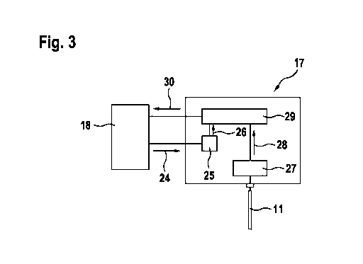
applied to
the suspension member based on information obtained from an elevator control
device for
controlling operation of the elevator;
- an electrical measuring device which is electrically connected to at least
one of the cords
in the suspension member and which is configured for measuring an electrical
characteristic of the suspension member upon applying an electrical voltage to
the at least
one of the cords;
a determination device which is configured for determining at least one of
(a) a critical deterioration state of the suspension member (23) upon
monitoring both:
the counted number of bending cycles applied to the suspension member (11),
and
the determined electrical characteristic of the suspension member (11);
and
(b) an unexpected deterioration state of the suspension member (23) based on
deriving a
current actual deterioration state of the suspension member based on the
determined
electrical characteristic and assuming a currently expected deterioration
state based on the
counted number of bending cycles and comparing the current actual
deterioration state
with the currently expected deterioration state.
For example, the determination device may be configured for determining a
critical
deterioration state of the suspension member upon each of:
an information indicating that the counted number of bending cycles applied
CA 02983976 2017-10-25
WO 2017/021265
PCT/EP2016/067970
- 27 -
to the suspension member as counted by the counter device exceeds an allowable
maximum number, and
an information indicating that the measured electrical characteristics of the
suspension member as measured by the electrical measuring device deviates from
a
reference characteristics by more than an allowable maximum deviation.
In other words, the deterioration state of a suspension member in an elevator
may be
continuously or repeatedly monitored using a specific monitoring device. This
device is,
on the one hand, adapted for counting a number of bending cycles applied to
the
suspension member. Such counting may be performed using a specific counter
device. On
the other hand, the device is adapted for measuring electrical characteristics
of the
suspension member. The device may then, using for example its determination
device,
decide on whether or not a critical or unexpected deterioration state of the
suspension
member is actually present.
Such decision may be based for example on each of the information indicating
that the
number of counted bending cycles exceeds an allowable maximum number and the
information indicating that the measured electrical characteristics of the
suspension
member deviates from reference characteristics by more than an allowable
maximum
deviation.
Alternatively, the determination device may for example verify whether an
expected
deterioration state of the suspension member which is assumed taking into
account
mainly the operational age of the suspension member (i.e. the number of
bending cycles
applied thereto) and the actual deterioration state of the suspension member
as derived
from its determined electrical characteristics correctly correspond to each
other or not.
Each of the counter device, the electrical measuring device and the
determination device
may be connected to an elevator control controlling operation of the elevator
and may
receive data or information from such elevator control or may transmit its own
data or
information to the elevator control. Such data exchange connection may be
established
such using hardwiring or may be wireless.
Accordingly, for example the counter device may receive data or information
from the
elevator control relating to trips performed in the elevator such that the
counter device
may derive its required information for counting the number of bending cycles
applied to
the suspension member from such elevator control information. Similarly, the
electrical
measuring device may be connected to the elevator control such that it may for
example
take into account information or data from the elevator control when
performing its own
CA 02983976 2017-10-25
WO 2017/021265
PCT/EP2016/067970
- 28 -
electrical measurements. The determination device may also be connected to the
elevator
control such that, for example, when a critical deterioration state of the
suspension
member is detected, such information may be transmitted to the elevator
control such that
the elevator control may then for example stop operation of the elevator,
limit operation
of the elevator, output an alarm or other information to users or operators of
the elevator
and/or initiate any other suitable countermeasures.
According to a third aspect of the present invention, an elevator is proposed.
The elevator
comprises the device according to an embodiment of the above described second
aspect
of the invention.
It shall be noted that possible features and advantages of embodiments of the
invention
are described herein partly with respect to a method for determining a
deterioration state
in a suspension member arrangement and partly with respect to a monitoring
arrangement
which is adapted for performing or controlling such method in an elevator.
Some features
are also described with reference to an elevator comprising such monitoring
arrangement.
One skilled in the art will recognize that the features may be suitably
transferred from one
embodiment to another, i.e. from the method to the device or vice versa, and
features may
be modified, adapted, combined and/or replaced, etc. in order to come to
further
embodiments of the invention.
In the following, advantageous embodiments of the invention will be described
with
reference to the enclosed drawings. However, neither the drawings nor the
description
shall be interpreted as limiting the invention.
Fig. 1 shows an elevator in which a method according to an embodiment of the
invention
may be applied.
Fig. 2 shows an exemplary suspension member.
Fig. 3 shows an exemplary embodiment of a monitoring arrangement according to
an
embodiment of the present invention.
Fig. 4 shows an alternative exemplary embodiment of a monitoring arrangement
according to an embodiment of the present invention.
Fig. 5 shows an example of an electrical measuring device for measuring
electrical
characteristics in a suspension member for a monitoring arrangement according
to an
embodiment of the present invention.
CA 02983976 2017-10-25
WO 2017/021265
PCT/EP2016/067970
- 29 -
Fig. 6 shows another example of an electrical measuring device for measuring
electrical
characteristics in a suspension member for a monitoring arrangement according
to an
embodiment of the present invention.
Fig. 7 visualizes electrical parameters to be induced or measured during
measuring
electrical characteristics of a suspension member with an electrical measuring
device as
shown in Fig. 6.
The figures are only schematic representations and are not to scale. Same
reference signs
refer to same or similar features throughout the figures.
Fig. 1 shows an elevator 1 in which a method according to embodiments of the
present
invention may be implemented.
The elevator 1 comprises a cabin 3 and a counterweight 5 which may be
displaced
vertically within an elevator shaft 7. The cabin 3 and the counterweight 5 are
suspended
by a suspension member arrangement 9. This suspension member arrangement 9
comprises one or more suspension members 11, sometimes also referred to a
suspension
traction media (STM). Such suspension members 11 may be for example ropes,
belts, etc.
In the arrangement shown in Fig. 1, end portions of the suspension members 11
are fixed
to a supporting structure of the elevator 1 at a top of the elevator shaft 7.
The suspension
members 11 may be displaced using an elevator traction machine 13 driving a
traction
sheave 15. The cabin 3 and the counterweight 5 may be held by the suspension
members
11 by winding the suspension members 11 around pulleys 16. An operation of the
elevator traction machine 13 may be controlled by a control device 18. For
example at
opposite end portions of the suspension member arrangement 9 components of a
monitoring device 17 for determining a deterioration state in the suspension
member
arrangement 9 may be provided.
It may be noted that the elevator 1 and particularly its suspension member(s)
11 and its
monitoring device 17 for determining the deterioration may be configured and
arranged
in various other ways than those shown in Fig. 1.
The suspension members 11 to be driven for example by the traction machine 13
may
utilize metal cords or ropes to support a suspended load such as the cabin 3
and/or the
counterweight 5 that is moved by the traction machine 13.
Fig. 2 shows an example of a suspension member 11 which is embodied with a
belt 19.
The belt 19 comprises a plurality of cords 23 which are arranged parallel to
and spaced
from each other. The cords 23 are enclosed in a matrix material 21 forming,
inter alia, a
CA 02983976 2017-10-25
=
WO 2017/021265
PCT/EP2016/067970
- 30 -
coating or jacket. Such coating may mechanically couple neighbouring cords 23.
The
coating may have a textured or profiled surface including longitudinal guiding
grooves.
The cords 23 may typically consist of or comprise wires made from a metal such
as steel.
The matrix material 21 may consist of or comprises a plastic or elastomeric
material.
Accordingly, the cords 23 are typically electrically conductive such that an
electric
voltage may be applied to and/or an electric current may be fed through the
cords without
significant losses. Furthermore, the cords 23 are preferably electrically
isolated from each
other via the interposed electrically insulating matrix material 21 such that,
as long as an
integrity of the coating is not deteriorated, an electrical current or voltage
between
neighbouring cords cannot be transmitted, i.e. no significant shunt current
can flow from
one cord 23 to another.
Figures 3 and 4 show an exemplary embodiment of a monitoring arrangement
including a
control device 18 and a monitoring device 17 for determining the deterioration
state in the
suspension member 11 of the elevator 1. The monitoring arrangement (17+18)
comprises
a counter device 25, an electrical measuring device 27 and a determination
device 29.
These devices 25, 27, 29 may be implemented as separate units. Alternatively,
these
devices 25, 27, 29 may be integrated into one single unit. Also, the control
device 18 and
the monitoring device 17 may be embodied as separate devices, or may me
embodied as a
single device, e.g. all incorporated in an elevator control unit for
controlling the overall
functionality or operation of the elevator. In one embodiment, the control
device 18 may
be substantially identical to the elevator control unit, while in others, the
control device
18 may be a part or subsystem of the elevator control unit. In further
embodiments, the
control device 18 may be separate from the elevator control unit. The
individual parts
may be distributed between the control device 18 and the monitoring device 17.
Devices
25-29 may be embodied as distinct devices or units in hardware, while an
embodiment as
a computer program, thus as software within a computing unit, e.g. of an
elevator control
unit or within the control device 18 or the monitoring device 17 may be
conceivable as
well.
E.g. in Fig. 3, substantially all of the above indicated devices 25-29 are, at
least logically,
associated with the monitoring device 17. In Fig. 4, e.g. the counter device
25 may be, at
least logically associated with the control device 18. Further, also the
determination
device 29
In the exemplary embodiment of Fig 3, the counter device 25 is connected to
the elevator
control device 18 such as to receive data or information from the control
device 18 as
visualised with the arrow 24. Such data or information may indicate for
example whether
CA 02983976 2017-10-25
WO 2017/021265
PCT/EP2016/067970
-31 -
or not the elevator is currently operated, i.e. whether or not the elevator
traction machine
13 currently displaces the suspension member 11. Furthermore, the control
device 18 may
provide data or information correlating to a current position of the cabin 3
and/or the
counterweight 5. Upon receiving such information, the counter device 25 may
derive
information allowing counting a number of bending cycles applied to the
suspension
member 11. For example, each time the suspension member 11 is displaced during
a trip
of the elevator 1 or each time a motion direction of the elevator is reversed,
the number of
bending cycles applied to the suspension member 11 is incremented. In other
words, one
alternative to increment the number of bending cycles may be embodied as a
trip
counter, even if successive trips are in the same direction of elevator/cabin
motion, while
another alternative is to only count, thus increment a bending cycle counter,
if the
direction of motion changes. This may be applied when counting bending cycles
for the
whole suspension member 11 or also during the sectional approach.
Preferably, the counter device 25 does not simply act like a trip counter. To
the contrary,
by for example taking into account the provided information about the current
position of
the cabin 3 and the counterweight 5, additional information may be derived
indicating
locations at which the suspension member 11 is currently being bent.
Accordingly, the
counter device 25 may be enabled to not simply count bending cycles for the
suspension
member 11 in its entirety but, instead, may count section bending cycles
applied to each
section of a multiplicity of sections forming the entire suspension member 11.
For
example, one section of the suspension member may correspond to a portion of
the
suspension member extending between two neighbouring floors of a building.
Principles,
further details and possible advantages of such preferred counter device 25
and the
method for counting bending cycles performed thereby are disclosed in the
applicant's
earlier patent applications WO 2010/007112 Al and EP 2 303 749 B1 which shall
be
incorporated herein in their entirety by reference.
The counted number of bending cycles applied to the suspension member 11 is
provided
from the counter device 25 to the determination device 29, as indicated with
the arrow 26.
The electrical measuring device 27 is electrically connected to the suspension
member 11.
For example, the electrical measuring device 27 comprises a voltage source for
generating an electric voltage V and applying such electric voltage V to one
or several
cords 23 of the suspension member 11. Preferably, the voltage source is
adapted for
generating two or more phases of an alternating voltage, these phases being
shifted
relative to each other and each phase being applied to one or a group of cords
23 or,
alternatively, to a separate resistor. As further detailed below, the
electrical measuring
= CA 02983976 2017-10-25
=
=
WO 2017/021265
PCT/EP2016/067970
- 32 -
device 27 may measure electrical characteristics of the suspension member by
applying
the electrical voltage to at least one of the cords 23 and by then monitoring
electrical
parameters in the cords 23.
The electrical measuring device 27 may then provide the information about the
electrical
characteristics of the suspension member 11 to the determination device 29 as
indicated
with the arrow 28.
The determination device 29 may use the information/data from the counter
device 25
and the electrical measuring device 27 for determining whether a critical
deterioration
state is present in the suspension member 11.
The presence of such critical deterioration state is assumed in case the
counted number of
bending cycles provided by the counter device 25 exceeds an allowable maximum
number. For example, such allowable maximum number of bending cycles may be
predetermined as a result of experiments performed with an exemplary non-
deteriorated
suspension member under normal operation conditions. In such experiments, it
is
repeatedly tested after having bent the suspension member multiple times
whether or not
the suspension member still has a sufficient load bearing capacity of more
than 60% or
more than 80% of its initial value. Typically, an allowable maximum number of
bending
cycles is determined from such experiments to be in a range of 15 million to
20 million
bending cycles but may also be higher or lower, dependent e.g. from specific
operating
conditions and/or characteristics of a specific type of suspension member 11.
Accordingly, at the latest after such allowable maximum number of bending
cycles has
been counted for the present suspension member 11, the determination device 29
will
assume that the repeated bendings will have deteriorated the suspension member
11 to a
degree such that a critical deterioration state has been reached and,
typically, the
suspension member 11 should be replaced.
As a second decisive parameter, the determination device 29 takes into account
the
electrical characteristics measured and provided by the electrical measuring
device 27. As
long as these electrical characteristics do not deviate excessively from
reference
characteristics, it is assumed that the suspension member 11 is operated under
normal
operation conditions, i.e. not for example damaged or corroded beyond a normal
state. As
long as this is true, the determination device 29 will base its decision
whether or not the
suspension member 11 can be further operated only on the determination of
whether or
not the suspension member 11 has been bent more than the allowable number of
bending
cycles. However, as soon as this is not true, i.e. electrical characteristics
are measured in
CA 02983976 2017-10-25
WO 2017/021265
PCT/EP2016/067970
- 33 -
the suspension member 11 which deviate from the reference characteristics by
more than
the allowable maximum deviation, it may be assumed that significant
deterioration or
damage occurred to the suspension member 11 which cannot only be attributed to
repeated bendings thereof. Based on the specific type of deviation from the
reference
characteristics, the determination device 29 may then decide whether this
deviation
indicates a critical deterioration state upon which operation of the elevator
1 should be
directly stopped or whether other countermeasures should be initiated.
Fig. 4 shows an alternative embodiment of a monitoring arrangement 17 for
determining
the deterioration state in the suspension member 11 of the elevator 1.
Therein, while still
forming part of the monitoring arrangement 17, the counter 25 is no more
included in a
same housing as the determination device 29 and the electrical measuring
device 27 but
forms part of the elevator control device 18. Typically, in such control
device 18, a
number of elevator trips or a number of motion reversals upon such trips is
counted and
such information may be provided to the determination device 29 as indicated
with the
arrow 26.
Further e.g., the control device 18 may equal the elevator control unit. Such
elevator
control unit may (already) comprise a counter device 25 for counting trips,
bending
cycles and/or sectional bending cycles. Here, monitoring device 17 may only
provide a
signal/ information as indicated with the arrow 30 to the elevator control
being indicative
of the determined electrical characteristic as such or being indicative of a
current actual
deterioration state of the suspension member. Said information may be provided
to the
control device 18/the elevator control unit, which in turn evaluates the
signal/information,
respectively, and conducts the method of the invention within the control
device 18/the
elevator control unit. As such, it is also feasible that the determination
unit 29 is, at least
logically, associated with/arranged within the control device 18/the elevator
control unit.
The determination unit 29 may even be a computing part within the control
device 18/the
elevator control unit, e.g. being embodied in the control program of the
control device
18/the elevator control unit. In such an embodiment, the signal/ information
as indicated
with the arrow 26 may not be present at all or may be a simple indication to
the
monitoring device 17 that a determination of an electrical characteristic
shall be
performed.
In Fig. 5 and 6, possible principles and features to be implemented in
examples of an
electrical measuring device 27 are briefly explained. However, it shall be
mentioned that
such principles and features are explained in significantly more details in
the applicant's
prior patent applications US 62/199,375 and US 14/814,558 (for the
implementation
CA 02983976 2017-10-25
WO 2017/021265
PCT/EP2016/067970
- 34 -
shown in Fig. 4) and EP 16 155 357 Al and EP 16 155 358 Al (for the
implementation
shown in Fig. 5). Accordingly, reference is made to these prior patent
applications, the
disclosure of which shall be incorporated in its entirety into the disclosure
of the present
invention.
Fig. 5 shows an example of a multi-phase alternating current circuitry 131
comprising
three electrically conductive legs 127 wherein both, a source side 133 and a
load side 135
are configured in a Wye-configuration. Alternating voltage sources Va, Vb, Vc
are
provided in a Wye-configuration at the source side 133. Resistors Zya, Zyb,
Zyc are
provided in a Wye-configuration at the load side 135. Both Wye-configurations
have a
neutral point 129 at which the voltage sources Va, Vb, Vc or the resistors
Zya, Zyb, Zyc,
respectively, are all interconnected. The alternating voltage sources Va, Vb,
Vc are
connected via the lines a, b, c forming the legs 127 to associated ones of the
resistors Zya,
Zyb, Zyc. Accordingly, current phases Ia, Ib, Ic of a multi-phase alternating
current may
be applied to each line a, b, c of the legs 27.
Furthermore, in the exemplary multi-phase alternating current circuitry 131 of
Fig. 4, a
neutral wire 137 is connected to each of the neutral points 129 at the Wye-
configuration
at the source side 133 and the Wye-configuration at the load side 135. In
other words, the
neutral wire 137 is connected between the common points 29 of the supply side
and the
load side of the multi-phase alternating current circuitry, respectively. The
neutral wire
137 comprises a resistance Zn. In the neutral wire, a bypass current In may
flow.
A multi-phase alternating current comprises at least two phases wherein in
each phase the
current alternates over time. There is a phase-shift between the phases such
that for
example a peak current strength in one phase is shifted by 2 7c/n (n=2, 3,
4,...) with
respect to a peak current strength of another phase. The currents may
alternate for
example in a sinusoidal manner. However, also other alternation patterns, such
as digital,
stepwise, or others, may be applied.
In other words and in the example of three phases, in electrical circuit
design, three-phase
electric circuits generally have three conductors for example formed by lines
a, b, c
carrying voltage waveforms that are 2 7t/3 radians (i.e. 1200 or 1/3 of a
cycle) offset in
time.
Where the three conductors carrying the voltage waveforms are "balanced", a
net sum of
phase currents throughout all legs 127 of the multi-phase alternating current
circuitry 131,
i.e. a vector sum of Ia, Ib, lc is 0 (i.e. Ia + Ib+ le = 0, wherein Ia, lb, lc
shall be vector
CA 02983976 2017-10-25
WO 2017/021265
PCT/EP2016/067970
- 35 -
currents and thus include information about their phases). In a balanced three-
phase
circuit, all three sources Va, Vb, Vc are generally represented by a set of
balanced three-
phase variables and all loads Zya, Zyb, Zyc as well as lines a, b, c within
the legs 127 of
the circuitry have equal impedances. Furthermore, in such balanced circuit,
not only the
net sum of the phase currents is 0, but also an electric bypass current In
through the
neutral wire 137 being connected in parallel to the legs 127 is 0 (i.e. In
=0).
Following Kirchhoff's voltage law, when there is an imbalance in the conductor
loads of
the three-phase circuit, any resulting imbalance of phase currents in the legs
127 of the
circuitry 131 will be resolved as a current In in the neutral wire 137 and/or
as a net sum
phase current throughout all phases a, b, c of the multi-phase alternating
current being no
more equal to 0.
Such deviation of the bypass current In through the neutral wire 137 or of the
net sum of
all other phase currents Ia, Ib, I, may be interpreted and named herein as
"electric indicator
current". As soon as this indicator current deviates from a reference current
value by
more than a predetermined difference value, this may be taken as signal
indicating that
critical deterioration has occurred within at least one of the suspension
members and
checking and, if necessary, replacing the suspension member may be initiated
for
example. The reference current value may be, for example a current value of
the bypass
current la or a net sum of the phase currents Ia, Ib, Ic measured with a non-
deteriorated
suspension member arrangement such as for example directly after fabrication
or
installation of a suspension member arrangement.
The indicator current may be measured in various ways. For example, a vector
net sum of
all currents I, Ib, Ic throughout all of the legs 127 of the multi-phase
alternating current
circuitry 131 may be measured together, i.e. with a common measuring
circuitry.
Alternatively, each of the phase currents la, Ib, Ia in the lines a, b, c
forming the legs 127
may be measured separately and a net sum of these separately measured phase
currents
may then be determined subsequently, for example in a summing device.
Alternatively,
the indicator current may be derived from the bypass current In flowing
through the
neutral wire 137 upon any imbalance within the multi-phase alternating current
circuitry
131.
For example, with reference to the circuitry 131 shown in Fig. 5, voltages Va,
Vb, Vc are
applied to lines a, b, c forming the legs 127 and are held constant, i.e.
equal to each other,
and 2 7c/3 radians shifted apart. At least one of the lines a, b, c may
comprise at least one
of the cords comprised in a suspension member of the suspension member
arrangement of
CA 02983976 2017-10-25
WO 2017/021265
PCT/EP2016/067970
- 36 -
the elevator. For a net sum (Ia + lb + In) and/or a bypass current In in the
neutral wire 37 to
be equal to 0 under initial conditions, such as when the suspension member is
newly
installed, voltage drops across each of the lines a, b, c plus voltage drops
across each of
the loads Zya, Zyb, Zyc in each of the legs 27 must be equal.
In practical terms, the voltage drops across for example steel cords in a
suspension
member will not necessarily be initially equal due to for example various
small
differences and tolerances created by for example manufacturing tolerances of
the steel
cords in the suspension member. In this case, the loads Zya, Zyb and Zyc may
be adjusted
to compensate for such differences until a desired initial current condition
for In = 0, i.e.
no current flow in the neutral wire, is obtained. Alternatively the multi
phase source
voltages Va, Vb, Vc 33 may be independently adjusted to likewise establish a
desired
initial current condition for In. Intuitively for those skilled in the art, an
alternative to
adjusting the loads Zya, Zyb, Zyc and/or the multi phase source voltages Va,
Vb, Vc for
an initial zero In current would be to capture a non-zero value of In as the
initial reference
current value.
Suspension members that contain multiple metal cords are generally capable of
having
the cords acting as electrical conductors or lines. The suspension member may
also be
construed with metal cords that are isolated electrically from each other by a
physical
separation, such as with electrically non-conductive materials like an
elastomeric coating.
Where the metal cords in suspension members are electrically isolated from
each other,
they may be connected for example in a Wye-configuration or a Delta-
configuration and
be part of various legs of a multi-phase alternating current circuitry. Each
of the cords
may then become an electrical conductor in the circuitry.
For example, in a Wye-configuration of Fig. 5, three isolated cords in a
suspension
member are represented by Zla, Zlb, Zlc. In an initially balanced state, the
sums of
resistances Zlx + Zyx (x = a, b, c) in each of the lines a, b, c formed by the
cords are
substantially equal. However, upon deterioration of one of the cords, the
resistance Zlx
created thereby in one of the lines changes and the entire multi-phase
alternating current
circuitry 31 comes into imbalance. Such imbalance may then be determined by
measuring
the indicator current In or (Ia + lb + lb). If this indicator current exceeds
a certain
predetermined value, this may be taken as indication that at least one of the
cords
comprised in a suspension member is significantly deteriorated and the
suspension
member may have to be checked and/or replaced.
=
CA 02983976 2017-10-25
WO 2017/021265
PCT/EP2016/067970
- 37 -
Instead of forming all lines a, b, c or, more generally, all legs 127 of a
multi-phase
alternating current circuitry 131 by including one of the cords of a
suspension member,
for example only one or a few of those lines may include cords of the
suspension
member. For example, as described further below with respect to various
examples, all
cords of a suspension member or of plural suspension members may be connected
in
series or in parallel and may be included into only one of the legs 127
whereas the other
legs 127 do not comprise any cords but are formed only with the loads Zyx.
These loads
Zyx may be fixed or dynamic. For example, dynamic loads may be implemented for
setting up initial conditions for In and/or compensating any temperature
effects modifying
electrical characteristics in the loads Zyx, the lines a, b, c, the cords
comprised in the
multi-phase circuitry and/or other components of the multi-phase circuitry.
It may be noted that setting up initial conditions for In and/or compensating
for the effects
of temperature or other phenomena may also be accomplished by dynamically
adjusting
the loads Zya, Zyb, Zyc and/or the multi phase source voltages Va, Vb, Vc.
As indicated above, further details of the approach for measuring electrical
characteristics
in suspension members 11 as briefly explained herein with respect to Fig. 4
are explained
in the applicant's prior patent applications US 62/199,375 and US 14/814,558.
Fig. 6 shows an exemplary embodiment of a device 217 for detecting a
deterioration state
in a suspension member arrangement 9 for an elevator 1. Therein, the
suspension member
arrangement 9 may comprise one or more suspension members 11 such as for
example
belts as shown in Fig. 2 including a plurality of electrically conducting
cords 23. In Fig.
5, the cords 223 are only indicated schematically as twelve elongate cords 223
being
arranged parallel to each other.
The multiplicity of cords 223 may be divided into two groups 224a, 224b of
cords. For
example, a first group 224a of cords may comprise all odd numbered cords 223
whereas a
second group 224b of cords may comprise all even numbered cords 223.
The device 217 comprises an alternating voltage generator arrangement G which
is
adapted for applying a first alternating voltage U1 to a first end 225a of the
first group
224a of cords 223 and for applying a second alternating voltage U2 to a first
end 225b of
the second group 224b of cords 223.
In the embodiment shown in Fig. 6, the alternating voltage generator
arrangement G
comprises a first alternating voltage generator GI and a second alternating
voltage
generator Gz. The two alternating voltage generators Gi, G2 may be separate
devices and
CA 02983976 2017-10-25
=
WO 2017/021265
PCT/EP2016/067970
- 38 -
may operate in principle independently from each other. However, the two
alternating
voltage generators Gi, G2 should be synchronized such as to operate with a
stationary
phase relationship with respect to each other.
The alternating voltage generators GI, 02 are electrically connected, on their
one side, to
an electrical ground potential, whereas, on their other side, they are
electrically connected
to the first ends 225a, 225b of the first and second groups 224a, 224b of
cords 223,
respectively. The alternating voltage generators GI, 02 generate first and
second generated
voltages UGI,UG2, respectively.
An internal electrical resistance of each of the alternating voltage
generators GI, 02 is
represented in Fig. 5 by R3, Ra. Due to such internal resistances R3, Ra, the
actual first and
second voltages Ul, U2 applied to the cords 223 may generally be lower than
the
generated voltages UGI,UG2generated by the alternating voltage generators GI,
G2
themselves.
The alternating voltage generator arrangement G with its alternating voltage
generators
GI, G2 is configured to generating the first and second alternating voltages
U1, U2 with
same waveforms and with a fixed phase difference of essentially 1800. Therein,
the
waveforms should differ from each other at most by an acceptable tolerance of
for
example less than 5% and the phase difference should differ from 180 at most
by an
acceptable tolerance of for example less than 10 , preferably less than 5 or
less than 2 .
In examples and embodiments described herein below, it will be assumed that
the
alternating voltage generator arrangement G has a specific exemplary
implementation in
which it generates first and second generated voltages UGI, UG2having an
amplitude of 6
V and oscillating around a DC voltage of 6 V. In other words, the first and
second
generated voltages UGI, UG2oscillate between U.,. = 0 V and U. = 12 V.
Therein, the
waveform is sinusoidal. An oscillation frequency is selected to be 280 Hz. The
internal
resistances R3, R4 are selected to be 450 Ohm.
However, it shall be noted that the alternating voltage generator arrangement
G may be
implemented in various other manners. For example, the first and second
generated
voltages UG I , UG2 may be generated with other waveforms such as rectangular
waveforms
or triangular waveforms. Furthermore, the amplitude and/or frequency of the
first and
second alternating generated voltages UGLUG2may be selected in various other
manners.
For example, the generated voltages UGLUG2may oscillate between other minimum
and
maximum voltages U.., U. Specifically, the alternating voltages do not
necessarily
have to oscillate around a fixed non-zero DC voltage but may also oscillate
around 0 V,
,
CA 02983976 2017-10-25
WO 2017/021265
PCT/EP2016/067970
- 39 -
i.e. Oscillate between a negative voltage ¨U. and a positive voltage +U.. Such
implementation may be advantageous with respect to electro-corrosion
characteristics.
Furthermore, the internal resistances R3, R4 may be selected in various
manners and may
be specifically adapted to a specific application, for example depending on
electrical
resistances generated by the cords 223 to which the first and second
alternating voltages
Ui, U2 shall be applied.
Furthermore, instead of providing the alternating voltage generator
arrangement G with
two separate alternating voltage generators GI, G2, a single alternating
voltage generator
may be provided and this single alternating voltage generator may provide for
a direct
output and an inverse output such that alternating generated voltages Uoi,UO2
may be
output with a phase-shift of 1800. For example, such single alternating
voltage generator
may be coupled to a transformer including for example a primary and a
secondary coil
wherein an inverse output voltage may be generated at a contact in a middle of
the
secondary coil, such inverse voltage output being shifted by 180 to a direct
voltage
output generated at outer contacts of the secondary coil. In such embodiment,
the first and
second alternating voltages U1, U2 are automatically synchronized with a
stationary
phase-shift of 180 such that, for example, no specific synchronization of two
separate
alternating voltage generators GI, G2 is required.
The first alternating voltage Ul is applied to the first end 225a of the first
group 224a of
cords 223 of a suspension member 11 whereas the second alternating voltage U2
is
applied to a first end 225b of the second group 224b of cords 223 of the same
suspension
member 11. Within one group of cords 224a, 224b, all cords 223 comprised in
this group
224a, 224b may be electrically connected to each other.
Preferably, the cords 223 of one group 224a, 224b are connected in series. In
such series
connection, for example all odd numbered cords 1, 3, 5, etc. are electrically
connected in
series to each other such as to form a kind of long single electrical
conductor. Similarly,
all even numbered cords 2, 4, 6, etc. may be connected in series. In such
implementation,
the first alternating voltage Ui may be applied for example to a first end
225a of the first
group 224a of cords 223 being formed by a free end of a cord 223 number 1, an
opposite
end of this cord number 1 being electrically connected in series to an end of
a cord
number 3, an opposite end of this cord number 3 again being electrically
connected to a
free end of a cord number 5 and so on. Accordingly, a second end 227a of this
first group
224a of cords 223 is formed by a free end of a last odd numbered cord 223.
Similarly, all
even numbered cords 223 may be connected in series such as to electrically
connect a
CA 02983976 2017-10-25
WO 2017/021265
PCT/EP2016/067970
- 40 -
first end 225b of this second group 224b of cords 223 to an opposite second
end 227b via
a single long conductor formed by the series of even numbered cords 223. In
such series
connection arrangement, both alternating voltages Ui, U2 applied to first ends
225a, 225b
of both groups 224a, 224b of cords 223 are transferred throughout the entire
series
connections formed in both groups 224a, 224b by the respective cords 223
comprised
therein. Accordingly, when no electric current flows, the first and second
alternating
voltages U1, U2 also apply to the second ends 227a, 227b of both groups of
cords 224a,
224b. However, in case any electric current is flowing through the cords 223
as a result of
the applied alternating first and second voltages Ui, U2, such current has to
be transferred
through the respective group 224a, 224b of cords 223 and thus experiences
electrical
resistances created by the respective cords 223. As a result, voltage drops
occur
throughout the respective cords 223. Accordingly, by measuring third and
fourth voltages
U3, U4 at opposite second ends 227a, 227b of each group 224a, 224b of cords
223,
information about a condition within the groups 224a, 224b of cords 223 may be
derived
as it may be for example determined whether any electric current flows through
the cords
223 in each of the groups 224a, 224b and, if this is the case, how such
current "behaves".
In order to connect the alternating voltage generator arrangement G to the
suspension
member and suitably interconnecting all cords 223 in advantageous series
connections, a
connector arrangement (not shown in Fig. 5 for clarity of visualization) for
establishing a
series connection of all even numbered cords in the suspension member and a
series
connection of all odd numbered cords in the suspension member and for
establishing an
electrical connection for applying the first and second alternating voltages
(U1, U2) to first
ends of the series connection of even numbered cords and the series connection
of odd
numbered cords, respectively, may be provided.
As a side note only, it shall be noticed that the first and second groups
224a, 224b of
cords 223 may be arranged and electrically connected in various other ways.
For
example, while it may be advantageous to include all even numbered cords and
all odd
numbered cords in one of the groups 224a, 224b of cords 223, respectively, it
may also be
possible to include each of the cords 223 of one or more suspension members 9
in other
configurations to the two groups 224a, 224b of cords 223. For example, all
cords 1 to n
may be comprised in the first group 224a, whereas all cords n+1 to x may be
comprised
in the second group of cords 224b. Preferably, both groups 224a, 224b of cords
223
comprise a same number of cords 223. Furthermore, while it may be beneficial
to connect
all cords 223 of one group 224a, 224b in series to each other, also parallel
electrical
CA 02983976 2017-10-25
WO 2017/021265
PCT/EP2016/067970
-41 -
connections of all or some of the cords 223 comprised in one of the groups
224a, 224b
may be possible.
At the second ends 227a, 227b of both groups 224a, 224b of cords 223, a first
voltage
measurement arrangement 231 and/or a second voltage measurement arrangement
233
may be provided as forming part of a determination unit 229. These components
229,
231, 233 are shown in Fig. 5 only in a schematic manner.
The first voltage measurement arrangement 231 may be adapted for determining a
summed voltage U+ which correlates to a sum of a third volume U3 and a fourth
voltage
U4. Therein, the third voltage U3 applies between the second end 227a of the
first group
224a of cords 223 and a common electrical potential such as a ground
potential. The
fourth voltage U4 applies between a second end 227b of the second group 224b
of cords
223 and the common electrical potential.
The second voltage measurement arrangement 233 is adapted for determining a
differential voltage U_ correlating to a difference between the third voltage
U3 and the
fourth voltage U4.
Therein, both the summed voltage U+ and the differential voltage U_ shall
"correlate" to
the sum and difference, respectively, of U3 and U4 in an unambiguous manner.
For
example, the summed voltage U+ may be equal to the sum U3 + U4 and the
differential
voltage U_ may be equal to the difference U3 - U4. Alternatively, the summed
voltage U+
and/or the differential voltage U_ may correlate to such sum U3 U4, U3 ¨ U4,
respectively, in other manners such as being for example a multiple thereof.
For example,
U+ may be equal to x * (U3+ U4) and/or U_ may be equal to y * (U3¨ U4), x and
y being
possibly any rationale number, for example x = y = 'A or x = y = 2, etc.
In principle, it may be sufficient to provide the device 217 with only one of
the first and
second voltage measurement arrangements 231, 233 as already from such single
voltage
measurement arrangement determining only the summed voltage U+ or the
differential
voltage U, some useful information about a current deterioration state of the
suspension
member 11 may be derived. However, in order to obtain more useful information
about
the deterioration state, it may be beneficial to provide the device 217 with
both the first
voltage measurement arrangement 231 and the second voltage measurement
arrangement
233 in order to enable for example distinguishing between various types or
degrees of
deterioration within the suspension member 211.
CA 02983976 2017-10-25
WO 2017/021265
PCT/EP2016/067970
- 42 -
In the embodiment shown in Fig. 6, the device 217 is provided with both the
first and
second voltage measurement arrangements 231, 233. Therein, the two voltage
measurement arrangements 231, 233 are implemented by including a first and a
second
voltage determining unit 235a, 235b. These voltage determining units 235a,
235b and/or
other voltage determining units comprised in voltage measurement arrangements
of the
device 217 may be e.g. electronic devices which are adapted for electronically
and
preferably automatically measure electric voltages within a circuitry.
Therein, the first
voltage determining unit 235a is connected on its one side to the second end
227a of the
first group 224a of cords 223 whereas the second voltage determining unit 235b
is
connected with one side to the second end 227b of the second group 224b of
cords 223.
An opposite side of both voltage determining units 235a, 235b is connected to
an electric
ground potential. Accordingly, the first and second voltage determining units
235a, 235b
are adapted for measuring the third voltage U3 and the fourth voltage U4,
respectively.
Both voltage determining units 235a, 235b are then connected to the
determination unit
229 in which the first voltage measurement arrangement 231 is adapted for
determining
the summed voltage U+ and the second voltage measurement arrangement 233 is
adapted
for determining the differential voltage U.
Additionally to the components of the circuitry explained herein before to be
used during
actually measuring the summed voltage and the differential voltage, the device
217
shown in Fig. 5 comprises a pull-up voltage source 236. This pull-up voltage
source 236
may apply a constant DC voltage to both first ends 225a, 225b of both groups
224a, 224b
of cords 223 during an idle mode in which the alternating voltage generator
arrangement
G is deactivated or couple-off. Such idle mode will be described further
below. The
constant DC voltage may be substantially equal to the maximum voltage U. of
the
alternating generated voltages Uci, UG2 generated by the alternating voltage
generator
arrangement G. The pull-up voltage source 36 comprises internal electrical
resistances
R2.
Furthermore, the device 217 may comprise a third and a fourth voltage
determining unit
235c, 235d for measuring the first and second voltages Ul, U2, respectively.
Depending
on the current flowing through the entire circuitry of the device 217, voltage
drops at the
internal resistances R3, R4 of the alternating voltage generator arrangement G
may differ
such that the first and second voltages U1, U2 may differ accordingly. Thus,
by measuring
the first and second voltages Ul, U2 with third and a fourth voltage
determining unit 35c,
35d, information about the electrical current flowing through the circuitry
may be
derived. This information then includes information about the deterioration
state of the
CA 02983976 2017-10-25
WO 2017/021265
PCT/EP2016/067970
- 43 -
suspension member 11 as the electrical current flowing through the circuitry
strongly
depends on electrical resistances occurring within the cords 223 of the
suspension
member II.
Next, a function principle of the device 217 and a method for detecting a
deterioration
state in a suspension member arrangement 9 performed thereby shall be
described in an
exemplary manner for a state where the suspension member 11 is non-
deteriorated, i.e.
neither the cords 223 nor the cover 21 is deteriorated or even damaged in any
manner and
therefore all cords 223 have same physical and electrical characteristics.
Voltages, which
are generated or which are measured during such method will be described with
reference
to Fig. 7.
In the method for monitoring the deterioration state, the alternating voltage
generator
arrangement G generates two alternating voltages UGI, UG2 which alternate in a
sinusoidal
manner with a frequency of 280 Hz and an amplitude of 6 V around a base direct
voltage
of 6 V. Such generated voltages Uoi, UG2 result in first and second
alternating voltages
U1, U2 (not shown in Fig. 4 for clarity reasons) which are applied to first
ends 225a, 225b
of the first group 224a and the second group 224b of cords 223 of the
suspension member
11, respectively. Of course, depending on whether or not an electric current
is flowing
through the circuitry, the first and second alternating voltages Ui, U2 may be
slightly
lower than the generated voltages UG1, UG2 due to a voltage drop in the
electrical
resistances R3, R4.
The first and second voltages Ul, U2 are then transmitted through the series
connection of
odd numbered cords 223 of the first group 224a and the series connection of
even
numbered cords 223 of the second group 224b, respectively, such that a third
and a fourth
alternating voltage U3, U4 occur at the opposite second ends 227a, 227b of
both groups of
cords 224a, 224b.
When there are no shunts and no electrical connection between these two second
ends
227a, 227b, no electrical current will flow such that the third and fourth
alternating
voltages U3, U4 will be the same as the applied first and second alternating
voltages U1,
U2. In other words, as long as no deterioration occurs in the suspension
member 11, the
third and fourth alternating voltages U3, U4 will exactly follow the applied
first and
second alternating voltages Ul, U2. Accordingly, upon determining such
alternating
voltage behaviours for the third and fourth alternating voltages U3, U4, it
may be
determined that the suspension member 11 is in a normal condition in which no
further
action is required.
CA 02983976 2017-10-25
WO 2017/021265
PCT/EP2016/067970
- 44 -
In such non-deteriorated state, due to the 1800 phase-shift between the third
and fourth
alternating voltages U3, U4, a summed voltage U+ corresponding to the sum of
the third
and fourth alternating voltages U3, U4 is a constant voltage, i.e. a DC
voltage being the
sum of the base DC voltages of the generated alternating voltages UGI, UG2
(i.e. in the
given example: U3 + U4 = 6 V + 6 V = 12 V). Accordingly, in such state, the
summed
voltage U+ has no alternating voltage component (i.e. U+,Ac = 0). A
differential voltage U_
corresponding to a difference of the third and fourth alternating voltages U3,
U4 alternates
with a same frequency as the generated voltages UGI, UG2 and with double the
amplitude
of these generated voltages UGI, Um around a DC voltage of 0 V (i.e. in the
given
example, U_ alternates between -12 and +12 V).
As will be described in further detail below, in cases where the suspension
member 11 is
deteriorated or even damaged, such initial conditions for the third and fourth
voltage U3,
U4 do no longer apply. Particularly, when at least one of the cords 223 in the
suspension
member 11 is broken or if there is a short-circuit between cords 223 or if
there is an
electrical connection to ground for at least one of the cords 223, either an
electrical
connection between the first ends 225a, 225b and the second ends 227a, 227b is
partly
interrupted (i.e. in the case of a broken cord) or electrical currents will
flow (i.e. in the
case of short-circuits or connections to ground). Accordingly, in such
deteriorated
conditions, the third and fourth voltages U3, U4 will no longer follow the
generated
voltages UGI, UG2 in the same manner as in the non-deteriorated state and, as
a result, the
summed voltage U+ and/or the differential voltage U_ will change their
behaviour.
Accordingly, any deviation from a state in which the summed voltage U+
comprises no
alternating voltage component U+,Ac and the differential voltage U_ comprises
an
alternating voltage being non-zero may be interpreted as indicating a
deterioration or
even a damage in the monitored suspension member 11.
While, in principle, a simple circuitry of the device 217 in which the second
ends 227a,
227b of the first and second groups 224a, 224b of cords 223 are not
electrically connected
might be sufficient for monitoring the suspension member 11 as it may at least
detect
whether or not the suspension member 11 is deteriorated or not, it may be
advantageous
to modify such open circuitry by connecting the second ends 227a, 227b of the
two
groups 224a, 224b of cords 223 via a connecting electrical resistance R,5.
Such connecting
electrical resistance R5 may have a resistance in a range of several tens or
hundreds of
Ohms, i.e. a resistance which is significantly higher than resistances
typically occurring
throughout the series connections of cords 223 in the suspension member 11
(such
resistances being typically in a range of some Ohms to a few tenth of Ohms,
depending
CA 02983976 2017-10-25
WO 2017/021265
PCT/EP2016/067970
- 45 -
on the length of the suspension member). In the example given in Fig. 5, R5 is
assumed to
be 100 Ohm.
Due to such electrical connection of the second ends 227a, 227b and the third
and fourth
voltages U3, U4 occurring at these second ends 227a, 227b, an electrical
current may flow
through the entire circuitry of the device 217. As a result of such electrical
current,
voltage drops will occur at all resistances included in such circuitry,
thereby directly
influencing all voltages Ux (x = 1, 2, 3, 4) at the various positions within
the circuitry. For
example, the first and second voltages U1, U2 will be lower than the generated
voltages
UGI, UO2 due to the internal resistances R3, R4. The third and fourth voltages
U3, U4 at the
second ends 27a, 27b will be lower than the first and second voltages Ul, U2
due to
electrical resistances within the series connections of cords 223 of the
suspension member
ii.
Using the principles of measurement indicated before, various types of damages
or
deterioration to suspension members may be detei mined. The following table
briefly
indicates some possibilities of detectable electrical characteristics relating
to specific
damages or deteriorations and of voltages occurring during respective
measurements.
U+ U- Phase angles Comment
AC DC AC DC U3 U4
OK No signal ¨1/2 U. Sinusoidal OV GI 02
signal
Broken cord Sinusoidal Um ax No signal OV Gx No load on
signal x side still Ut and
U2
2Unlax peak connected
to peak
STM not No signal OV No signal OV - No load on
attached or U1 and U2
both cord pairs
broken
Multiple No signal OV No signal OV - Load on
connections to Ui and U2
ground Elevator
(measurement must move to
mode) detect
all faults
Single Sinusoidal <=1/2 Umax Sinusoidal <= Ox Elevator
connection to signal signal <= 1/2 x side not must move
to
ground U3+U4 Uõ,õõ having ground detect
(measurement fault all faults
mode)
Adjacent No signal Um No signal OV - Elevator
CA 02983976 2017-10-25
WO 2017/021265
PCT/EP2016/067970
- 46 -
connection of must move
cords to detect
(symmetrical) all faults
Adjacent Sinusoidal Umax No signal OV Gx Load on
connection of signal x side of the u1 and U2
cords generator Elevator
(asymmetrical) being closer to must move
the fault to detect
all faults
Damaged Deviation from initial values
cords
As indicated above, further details of the approach for measuring electrical
characteristics
in suspension members 11 as briefly explained herein with respect to Fig. 6
and 7 are
explained in the applicant's prior patent applications EP 16 155 357 Al and EP
16 155
358 A 1
Finally, it should be noted that terms such as "comprising" do not exclude
other elements
or steps and that terms such as "a" or "an" do not exclude a plurality. Also
elements
described in association with different embodiments may be combined. It should
also be
noted that reference signs in the claims should not be construed as limiting
the scope of
the claims.