Note: Descriptions are shown in the official language in which they were submitted.
RIGID ENT TOOL
FIELD OF THE INVENTION
This invention relates generally to surgical tools,
and specifically to a rigid surgical tool which is
tracked while in a patient.
BACKGROUND OF THE INVENTION
In a surgical procedure where a tool, such as an ENT
(ear, nose and throat) tool, is inserted into a patient,
it is important to track the inserted portion of the
tool. The following patents and patent applications
provide methods for performing such tracking.
U.S. Patent Application 2006/0004286 to Chang et al.
describes systems for performing image guided
interventional and surgical procedures, including
various procedures to treat sinusitis and other
disorders of the paranasal sinuses, ears, nose or
throat.
U.S. Patent Application 2012/0143029 to Silverstein
et al. describes a guidance system for assisting with
the insertion of a needle into a patient body is
disclosed. The guidance system may have an imaging
device including a probe for producing an image of
an internal body portion target, such as a vessel.
One or more sensors are included with the probe.
The sensors sense a detectable characteristic
related to the needle, such as a magnetic field of
a magnet included with the needle.
U.S. Patent Application 2012/0226100 to Greenburg et
al. describes a system for extending the visual
1
CA 2984336 2017-10-31
capabilities and working channel of a bronchoscope.
The system includes a probe having optic and/or
tracking capabilities at a distal tip of the
bronchoscope, and that is capable of being advanced
through the working channel of a standard
bronchoscope.
U.S. Patent Application 2014/0066901 to Dinger, III
et al. describes an instrument for treating an
anatomical opening such as a paranasal sinus. The
application refers to an image guidance navigation
system used for positioning a therapeutic
component.
U.S. Patent 6,321,109 to Ben-Haim et al. describes a
method of excavating tissue in a body. The patent
refers to a position sensing device, which senses the
instantaneous position of the tip of a catheter. The
position sensor is stated to be an AC magnetic field
receiver, which senses an AC magnetic field generated by
a transmitter.
U.S. Patent Application 2008/0275483 to Makower et
al. describes navigation devices for use in
conjunction with image guidance or navigation
systems and hand held devices.
U.S. Patent 8,721,591 to Chang et al. describes
apparatus for dilating ostia of paranasal sinuses. The
apparatus may include sensors which are electromagnetic
location sensors.
U.S. Patent 5,071,409 to Rosenberg describes a
plunger which includes a position sensor for sensing the
position of a piston within a cylinder. The position
2
CA 2984336 2017-10-31
sensor may be in the form of a magnetic core carried by
the plunger.
SUMMARY OF THE INVENTION
An embodiment of the present invention provides
apparatus, including:
a rigid tube enclosing a lumen, configured to be
inserted into a cavity of a human patient;
a groove formed in a distal end of the tube;
a conductive coil of insulated wiring wound in the
groove; and
a sleeve covering the rigid tube so as to completely
enclose the conductive coil.
In a disclosed embodiment the apparatus includes a
channel, connected to the groove and formed on the tube,
and one or more conductors laid in the channel connected
to ends of the conductive coil. Typically the sleeve is
configured to cover the channel so as to completely
enclose the one or more conductors. The distal end may be
chamfered, and the sleeve connects to the chamfered
distal end so that an outer surface of the sleeve and the
chamfered distal end form a continuous smooth surface.
In a further disclosed embodiment a handle is
connected to a proximal end of the tube. Typically, the
handle includes circuitry connected to the conductive
coil so as to receive signals generated therein.
There is further provided, according to an
embodiment of the present invention, a method, including:
providing a rigid tube enclosing a lumen, the rigid
tube being configured to be inserted into a cavity of a
human patient;
forming a groove in a distal end of the tube;
3
CA 2984336 2017-10-31
winding a conductive coil of insulated wiring in the
groove; and
covering the rigid tube with a sleeve so as to
completely enclose the conductive coil.
The present disclosure will be more fully understood
from the following detailed description of the
embodiments thereof, taken together with the drawings, in
which:
4
CA 2984336 2017-10-31
BRIEF DESCRIPTION OF THE DRAWINGS
Fig. 1 is a schematic illustration of an ENT (ear,
nose, and throat) system, according to an embodiment of
the present invention; and
Fig. 2 and Fig. 3 are respectively schematic
diagrams of an ENT suction tool and of a cross-section of
a distal portion of a tube of the tool, according to an
embodiment of the present invention.
5
CA 2984336 2017-10-31
DETAILED DESCRIPTION OF EMBODIMENTS
Overview
It is important to track the distal end of an ENT
(ear, nose, and throat) tool used in an ENT procedure,
because of the proximity of the end to sensitive areas
such as the eyes, optic nerves, and brain. The inventors
have found that even though the distal end may be tracked
by attaching a tracking sensor to the proximal end of an
ENT tool, and adding a vector to the proximal end
location, in practice errors are associated with the
added vector making the generated distal end value
unacceptable.
Embodiments of the present invention form a rigid
ENT tool with a magnetic tracking sensor, in this case a
single coil, built into the tool. The tool is typically a
rigid suction tool, but the concepts described herein can
be applied to other rigid tools such as cutters and
graspers.
A circular groove is cut into the distal end of the
basic tool, and a coil is wound in the groove. A channel
is also cut from the circular groove, up to the proximal
end of the tool. Conductors connecting the coil to the
proximal end are positioned in the channel. The channel
and the groove are then covered by a metal sleeve, so
that the basic tool external surface returns to its
initial un-indented form.
Detailed Description
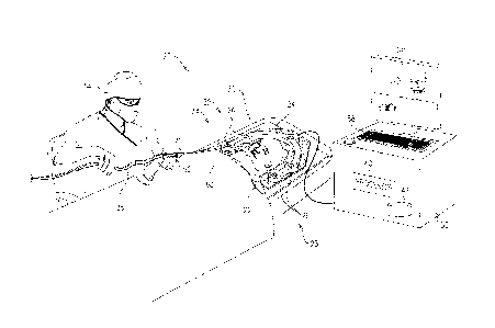
Reference is now made to Fig. 1, which is a
schematic illustration of an ENT (ear, nose, and throat)
system 20, according to an embodiment of the present
6
CA 2984336 2017-10-31
invention. In the following description system 20 is
assumed to be used to perform a nasal sinus procedure on
a patient 22, and during the procedure a suction tool 21
is used. As is described in more detail below, tool 21
comprises a magnetic sensor 32 at its distal tip, and the
sensor is tracked during the procedure by a magnetic
tracking system 23. For the tracking to be effective, in
system 20 frames of reference of a CT (computerized
tomography) image of patient 22 and of magnetic tracking
system 23, are registered. The method of registration
used may comprise any registration method known in the
art.
While the CT image may typically comprise a magnetic
resonance imaging (MRI) image or a fluoroscopic image, in
the description herein the image is assumed to comprise,
by way of example, a fluoroscopic CT image,
Prior to and during the sinus procedure, a magnetic
radiator assembly 24, comprised in the magnetic tracking
system, is positioned in proximity to the patient's head.
Assembly 24 comprises magnetic field radiators 26 which
are fixed in position and which transmit alternating
sinusoidal magnetic fields into a region 30 wherein the
head of patient 22 is located. By way of example,
radiators 26 of assembly 24 are arranged in an
approximately horseshoe shape around the head of patient
22. However, alternate configurations for the radiators
of assembly 24 will be apparent to those having ordinary
skill in the art, and all such configurations are assumed
to be comprised within the scope of the present
invention. The Carta system produced by Biosense
Webster, of Diamond Bar, CA, uses a tracking system
similar to that described herein for finding the location
7
CA 2984336 2017-10-31
and orientation of a coil in a region irradiated by
magnetic fields.
Suction tool 21 comprises a probe handle 52 which is
at the proximal end of the tool, and the suction tool
also comprises a rigid tube 60, which is at the distal
end of the tool. Handle 52 allows a physician 54 to
manipulate the tool. Flexible tubing 59 connects to
handle 52, the tubing permitting drainage of fluid
through a lumen 34 of tube 60. In addition cabling 36 is
connected to handle 52, the cabling enabling power to be
transferred to elements in the handle, as well as
enabling signals, originating in sensor 32, to be
conveyed from the handle.
Elements of system 20, including radiators 26, are
controlled by system processor 40. The processor is also
configured to receive the signals originating in sensor
32, and process the signals to derive location and
orientation values for the sensor. Processor 40 may be
mounted in a console 50, which comprises operating
controls 58 that typically include a keypad and/or a
pointing device such as a mouse or trackball. Console 50
connects to the radiators via a cable and/or wirelessly.
Physician 54 uses operating controls 58 to interact with
the processor while performing the ENT procedure using
system 20. While performing the procedure, the processor
may present results of the procedure on a screen 56.
Processor 40 uses software stored in a memory 42 to
operate system 20. The software may be downloaded to
processor 40 in electronic form, over a network, for
example, or it may, alternatively or additionally, be
provided and/or stored on non-transitory tangible media,
such as magnetic, optical, or electronic memory.
8
CA 2984336 2017-10-31
Processor 40 uses the software, inter alia, to
operate magnetic radiators 26 of assembly 24, and to
analyze the signals received from sensor 32. As stated
above the radiators transmit sinusoidal alternating
magnetic fields of different frequencies into region 30,
including the head of patient 22, and the fields from the
radiators induce signals in sensor 32.
Fig. 2 and Fig. 3 are respectively schematic
diagrams of ENT suction tool 21 and of a cross-section of
a distal portion of rigid tube 60 of the tool, according
to an embodiment of the present invention. As is shown in
Fig. 2 rigid, inflexible, tube 60 is formed as a distal
end of tool 21. Tube 60 is fixedly attached to a casing
74, which typically encloses circuitry 82 coupled to
sensor 32, and which forms part of handle 52. The
circuitry typically includes a pre-amplifier which
receives signals from sensor 32, and which converts the
signals to a form that may be conveyed, via cabling 36,
to processor 40 without introducing noise into the
signal. A tubular fluid connection 80 is also fixedly
attached to casing 74, and the connection connects to
tubing 59 (Fig. 1) and is configured so that during the
ENT procedure body fluids may drain through lumen 34 of
tube 60, and connection 80, without leaking into casing
74.
To operate efficiently, tube 60 has to meet a number
of sometimes conflicting constraints. Since tube 60 is to
act as a suction device, its interior lumen should be as
large as possible, and the lumen should have no internal
obstructions which could impede the flow of material in
the lumen. However, since the tube is to be used in an
internal procedure on a patient, the outside dimensions
9
CA 2984336 2017-10-31
of the tube should be as small as possible so as to
reduce any trauma caused by the entry of the tube into
the patient. In addition, also to reduce the chance of
trauma, the external surface of the tube should be
smooth, without indentations or protuberances. Since the
tube is to be used in surgery, surfaces of the tube that
may contact a patient should be biocompatible, and the
tube itself should be able to be sterilized, for example
in an autoclave.
Fig. 3 illustrates how tube 60 is constructed to
satisfy the constraints listed above. Tube 60 comprises a
cylindrical biocompatible conduit 90, also herein termed
tube 90, which encloses lumen 34. A circular groove 92 is
formed in an outer surface 94 of the conduit, at the
distal tip of the conduit. A channel 96 is formed in the
outer surface, leading from groove 92 to casing 74. By
way of example, in the embodiment illustrated in Fig. 3,
channel 96 is formed as a helical channel, but in other
embodiments the channel may be any convenient shape
formed in the outer surface, including a straight line,
connecting groove 92 to casing 74.
A coil 98 of insulated wiring is wound in groove 92,
the coil acting as sensor 32. Ends of the coil are
connected to a pair of insulated conductors 100, which
are laid in channel 96, and which connect the ends of the
coil to circuitry 82. In one embodiment the wiring has a
diameter of approximately 40 pm, the groove has a depth
of approximately 100 pm, and the channel has a
semicircular cross-section with a diameter of
approximately 100 pm.
Once coil 98 and conductors 100 have been formed and
positioned as described above, channel 96 and groove 92
CA 2984336 2017-10-31
are covered by a rigid cylindrical biocompatible metal
sleeve 102 so that the conductors of the channel and the
groove are completely enclosed. The sleeve is typically
an interference fit to the external surface of tube 90.
In one embodiment the sleeve and tube 90 are constructed
from stainless steel or titanium, and after inserting the
sleeve over tube 90, the two are welded together. A
distal tip 104 of conduit 90 may then be chamfered, as
shown in Fig. 3, so that the outer surface of tube 60,
comprising the outer surface of sleeve 102 and an
external distal part of conduit 90, i.e., chamfered
distal tip 104, forms a continuous, smooth, and non-
indented surface.
In a disclosed embodiment sleeve 102 has an external
diameter of 3.57 mm and an internal diameter of 3.4 mm,
and conduit 90 has an external diameter of 3.4 mm and an
internal diameter of 3.1 mm.
While the description above has generally referred
to a suction tool, it will be understood that the
concepts described herein may be applied, mutatis
mutandis, to other tube based tools, as well as to other
tools such as a shaver and a microdebrider.
It will be appreciated that the embodiments
described above are cited by way of example, and that the
present invention is not limited to what has been
particularly shown and described hereinabove. Rather,
the scope of the present invention includes both
combinations and subcombinations of the various features
described hereinabove, as well as variations and
modifications thereof which would occur to persons
skilled in the art upon reading the foregoing description
and which are not disclosed in the prior art.
11
CA 2984336 2017-10-31