Note: Descriptions are shown in the official language in which they were submitted.
Title
FLUID STORAGE RESERVOIR
Scope of the Invention
[0001] This invention relates to a method of storing a product that
contains a volatile
component within a fluid storage reservoir formed with enclosing walls having
a
permeability that permits limited passage of the volatile component from the
storage
reservoir to the atmosphere, preferably with the method increasing the shelf
life of the
product stored.
[0002] The invention further relates to a fluid storage reservoir with a
first container
containing a fluid product to be dispensed including a volatile component and
a second
container containing a sacrifice material including the same volatile
component with a n
intermediate transfer wall shared by both the first container and the second
container for
transfer of the volatile component between the first container and the second
container.
Background of the Invention
[0003] Surface cleaners and hand sanitizers are known which include as an
active
ingredient ethanol typically with water in solutions containing 30 to 95%
ethanol by weight
and, more preferably, ethanol in the range of 40 to 90% and, more preferably,
ethanol in the
range of 60 to 80% and, most preferably, in the range of about 70%. The
surface cleaners
and hand sanitizers may include other components such as isopropyl alcohol,
glycerine,
carbomer, fragrances, aminomethyl propanol, propylene, glycol, isopropyl
myristate and
tocopheryl acetate. One known surface cleaner and hand sanitizer sold under
the trademark
PURELLTM and has as an active ingredient 70% weight/weight ethanol in an
aqueous
solution.
[0004] Ethanol kills organisms by denaturing their proteins and is
effective against most
bacterial fungus and many viruses. Ethanol is a volatile component. A hand
sanitizer
containing ethanol can be used by wetting one's hands with the hand sanitizer,
briskly
rubbing one's hands together until they become dry due to the evaporation of
the hand
sanitizer, notably, the ethanol at room temperatures.
1
CA 2984761 2017-11-06
,
[0005] It is well known to store ethanol based surface cleaners and hand
sanitizers in
bags, bottles and other receptacles. Ethanol based surface cleaners and hand
sanitizers are
known to be stored ready for use in various fluid storage reservoirs which may
or may not
incorporate a pump mechanism for dispensing the fluid. For example, product
storage
reservoirs are known that comprise a plastic bag or bottle and a pump assembly
which
together as a unit are removably insertable into a fluid dispenser for
discharge of the cleaning
fluid and subsequent removal and replacement as disclosed in U.S. Patent
8,479,950 to
Ophardt et al, issued July 9, 2013 and U.S. Patent 8,365,954 to Ophardt et al,
issued
February 5, 2013. Various other product storage reservoirs are known including
a collapsible
bag formed from a thin flexible plastic material such as polyethylene
containing the liquid to
be dispensed.
[0006] Towards minimizing the cost of the fluid storage reservoirs, it is
preferred to
make the reservoirs from low cost plastic materials. Fluid storage reservoirs
are often
preferred to be collapsible by forming the reservoirs to have thin, flexible
walls. Using
reservoirs with thin walls has the advantage of minimizing the amount of
material used to
make a fluid storage reservoir. A disadvantage which arises from using with
most plastics
and notably inexpensive plastics such as polyethylene in forming a fluid
storage reservoir is
that the plastics are not impermeable to volatile compounds such as ethanol,
rather the
plastics have a permeability that lets volatile components such as ethanol
pass through
enclosing walls of the fluid storage reservoir. The disadvantage of the
plastics having a
permeability that lets volatile components pass through enclosing walls of a
fluid storage
reservoir increases as the thickness of the enclosing walls are reduced.
[0007] The inventors of the present application have appreciated the
disadvantage that
with the passage of time, volatile components such as ethanol, in stored
products such as a
hand sanitizer or surface cleaner, can permeate through the walls of the fluid
storage
reservoirs reducing both the volume of the stored product and the
concentration of the
volatile components from the stored product. The inventors of the present
application have
appreciated the disadvantage that with the passage of time, fluid reservoirs
containing
volatile components can have the volume of the stored product and the
percentage of the
2
CA 2984761 2017-11-06
volatile component in the stored product reduced such that the stored product
becomes not
acceptable for use or for sale. For example, a reduction in the product volume
or a reduction
in the concentration of the volatile component beyond predetermined levels may
render the
product inappropriate to sell or less than desirably effective. The present
inventors have also
appreciated that in the operation of facilities which fill product storage
reservoirs with
products containing volatile components such as ethanol based surface cleaners
and hand
sanitizers, it is often desired from a point of cost reduction to process a
large batch of the
product and to place the product of the batch within a large number of smaller
fluid storage
reservoirs, effectively at the same time. In the normal storage life of such
smaller fluid
storage reservoirs after becoming filled, they are warehoused, moved through
distribution
channels, and stored by the end user before being used by the end user. Many
of these
smaller fluid storage reservoirs are often stored for an extended period of
time before they
are used. Not infrequently, many of such filled smaller fluid storage
reservoirs are stored for
extended periods of time of many months or 1, 2 or more years before the
product will be
used.
Summary of the Invention
[0008] To at least partially overcome some of these disadvantages of
previously known
devices, the present invention provides a method of increasing the shelf life
of a product
containing a volatile component by storing the product in an enclosed first
container and
providing a portion of an enclosing wall of the first container in contact
with a sacrifice
material containing the volatile component.
[0009] To at least partially overcome some of these disadvantages of
previously known
devices, the invention also provides a fluid storage receptacle comprising a
first enclosed
container containing a fluid product to be dispensed that includes a volatile
component and a
second enclosed container containing a sacrifice material that includes the
volatile
component with the first container and the second container sharing an
intermediate transfer
wall for transfer of the volatile component between the first container and
the second
container.
3
CA 2984761 2017-11-06
_,..
[0010] In one aspect, the present invention provides a fluid storage
reservoir comprising:
100111 a first container defining an enclosed interior within an enclosing
wall member,
[0012] the interior of the first container containing a product to be
dispensed,
[0013] the enclosing wall member of the first container including an
intermediate transfer
wall with an inner surface and an outer surface,
[0014] the intermediate transfer wall defining at least in part the
interior of the first
container with the inner surface of the intermediate transfer wall in contact
with the product,
[0015] a second container defining an enclosed interior within an
enclosing wall member,
[0016] the interior of the second container containing a sacrifice
material,
[0017] the enclosing wall member of the second container including the
intermediate
transfer wall,
[0018] the intermediate transfer wall defining at least in part the
interior of the second
container with the outer surface of the intermediate transfer wall in contact
with the sacrifice
material,
[0019] the product comprising a fluid including a volatile component,
[0020] the sacrifice material comprising a fluid including the volatile
component,
[0021] the intermediate transfer wall having a permeability between the
first surface and
the second surface selected from the following group:
[0022] (i) a permeability that permits passage of the volatile component
through the
intermediate transfer wall from the interior of the second container to the
interior of the first
container, and
[0023] (ii) a permeability that permits passage of the volatile component
through the
intermediate transfer wall from the interior of the second container to the
interior of the first
container and from the interior of the first container to the interior of the
second container,
[0024] an escape transfer wall selected from the group consisting of:
[0025] (a) a first escape transfer portion of the enclosing wall member of
the first
container with an inner surface of the first escape transfer portion in
contact with the product
and an outer surface of the first escape transfer portion in contact with the
atmosphere, the
first escape transfer portion of the enclosing wall member of the first
container having a
4
CA 2984761 2017-11-06
. ,
permeability that permits passage of the volatile component through the
enclosing wall
member of the first container from the interior of the first container to the
atmosphere, and
[0026] (b) a second escape transfer portion of the enclosing wall
member of the second
container with an inner surface of the second escape transfer portion in
contact with the
sacrifice material and an outer surface of the second escape transfer portion
in contact with
the atmosphere, the escape transfer portion of the enclosing wall member of
the second
container having a permeability that permits passage of the volatile component
through the
enclosing wall member of the second container from the interior of the second
container to
the atmosphere.
[0027] In a 2'1 aspect, as in the 1st aspect, the present invention
provides a fluid storage
reservoir wherein the intermediate transfer wall having a permeability that
permits passage of
the volatile component through the intermediate transfer wall between the
interior of the first
container and the interior of the second container.
[0028] In a 3rd aspect, as in the 1st or 2nd aspect, the present
invention provides a fluid
storage reservoir wherein the product when placed in the first container
having the volatile
component in an initial product concentration, and
[0029] the sacrifice fluid when placed in the second container having
the volatile
component in an initial sacrifice concentration equal to or greater than the
initial product
concentration.
[0030] In a 4th aspect, as in the 3rd aspect, the present invention
provides a fluid storage
reservoir wherein the initial sacrifice concentration is equal to or greater
than the initial
product concentration.
[0031] In a ,-th
D aspect, as in any one of the 1st to 4th aspects, the
present invention
provides a fluid storage reservoir container wherein the enclosing wall member
of the first
container includes a product outlet opening and a closure element closing the
product outlet
opening.
[0032] In a 6th aspect, as in the 5th aspect, the present invention
provides a fluid storage
reservoir container wherein the second container having an opening sealably
engaged to the
CA 2984761 2017-11-06
'
first container about the product outlet opening with the first container
other than the product
outlet opening and the closure element within the interior of the second
container.
[0033] In a 7th aspect, as in the 5th or 6th aspect, the present invention
provides a fluid
storage reservoir wherein the first container is disposed about an axis with
the enclosing wall
member of the first container including a circumferential side wall of the
first container
spaced radially from the axis, and closed at each axial end by first and
second end walls of
the first container, the first end wall of the first container carrying the
product outlet opening,
[0034] the second container is also disposed about the axis with a
circumferential side
wall of the second container spaced radially outwardly from the
circumferential side wall of
the first container and closed at each axial end by first and second end walls
of the second
container,
[0035] an annular side space defined between the circumferential side wall
of the first
container and the circumferential side wall of the second container,
[0036] the intermediate transfer wall including the circumferential side
wall of the first
container.
[0037] In an 8th aspect, as in the 7t11 aspect, the present invention
provides a fluid storage
reservoir wherein the escape transfer portion of the enclosing wall member of
the second
container including the circumferential side wall of the second container, and
[0038] the escape transfer wall including the escape transfer portion of
the enclosing wall
member of the second container.
[0039] In a nth
aspect, as in the 7th aspect, the present invention provides a fluid storage
reservoir wherein the first end wall of the second container is sealably
engaged with the first
container annularly about the outlet opening forming an annular first end
space between the
first end wall of the first container and the first end wall of the second
container opening into
the annular side space.
[0040] In a I 0th aspect, as in any one of the 6th to 9th aspects, the
present invention
provides a fluid storage reservoir wherein the second end wall of the second
container is
disposed axially outwardly from the second end wall of the first container.
6
CA 2984761 2017-11-06
, -
[0041] In an 11th aspect, as in the 10th aspect, the present invention
provides a fluid
storage reservoir wherein the second end wall of the second container disposed
axially
spaced from the second end wall of the first container forming a second end
space between
the end wall of the first container and the end wall of the second container
opening annularly
into the annular side space.
[0042] In a 12th aspect, as in the 1 1 th aspect, the present
invention provides a fluid storage
reservoir including a spacer located axially between the enclosing wall member
of the first
container and the enclosing wall member of the second container to space the
outer surface
of the enclosing wall member of the first container from the inner surface of
the enclosing
wall member of the second container maintaining a space there between.
[0043] In a 13th aspect, as in any one of the 6th to 12th aspects, the
present invention
provides a fluid storage reservoir wherein the first container having a
rigidity that maintains
the circumferential extent of the circumferential side wall of the first
container yet permits
axial movement of the second end wall of the first container towards the first
end wall of first
container to accommodate reductions in the volume of the product up to at
least a maximum
amount, preferably 5% by volume of the interior of the first container,
[0044] a biasing mechanism urging the second end wall of the second
container to move
axially toward the first end wall of the first container forcing the sacrifice
material into the
annular space.
[0045] In a 14th aspect, as in the 13t11 aspect, the present invention
provides a fluid storage
reservoir wherein the second container having a rigidity that maintains the
circumferential
extent of the circumferential side wall of the second container yet permits
axial movement of
the second end wall of the second container towards the first end wall of
second container.
[0046] In a 15th aspect, as in the 6th aspect, the present invention
provides a fluid storage
reservoir wherein the axis is vertical with the first end walls of the first
container and the
second container being vertically above the respective second end walls of the
first container
and the second container,
[0047] the first container having a rigidity that maintains the
circumferential extent of the
side walls yet permits axial upward movement of the second end wall of first
container to
7
CA 2984761 2017-11-06
'
accommodate reductions in the volume of the product up to a maximum amount,
preferably
5% by volume,
[0048] a biasing mechanism urging the second end wall of the second
container to move
axially upwardly relative the first end wall of the second container forcing
the fluid of the
sacrifice material upwardly into the annular space and the first end space to
fill the same
while there is an adequate volume of the sacrifice material in the interior of
the outer
container.
[0049] In a l6 aspect, as in any one of the 1st to 15th aspects, the
present invention
provides a fluid storage reservoir wherein the volatile component is an
alcohol and the
product is a cleaning composition.
[0050] In a 17th aspect, as in the 1 e aspect, the present invention
provides a fluid storage
reservoir wherein the product is an alcohol based surface disinfectant
containing at least 40%
of the alcohol as the volatile component,
[0051] the sacrifice material comprises a solution of the alcohol having
the alcohol in a
percentage at least as great as the same percent of the alcohol in the alcohol
based surface
disinfectant.
[0052] In an 18th aspect, as in any one of the 1st to 17th aspects, the
present invention
provides a fluid storage reservoir including a mechanism for removing the
sacrifice material
from the second container.
[0053] In a 19th aspect, the present invention provides a method of
increasing the shelf
life of a product to be dispensed containing an initial concentration of a
volatile component,
the method comprising:
[0054] storing the product in an enclosed first container defining an
enclosed interior
within an enclosing wall member having a portion with a permeability that
permits passage
of the volatile component through the enclosing wall member between an inner
surface of the
enclosing wall member open into the interior and an opposed outer surface of
the enclosing
wall member,
[0055] providing at least a transfer segment of the outer surface of the
portion of the
enclosing wall in contact with a sacrifice material containing the volatile
component in an
8
CA 2984761 2017-11-06
,
initial concentration greater than the volatile component occurs in atmosphere
with the
transfer segment having a permeability that permits passage of the volatile
component
through the transfer segment from the interior of the second container to the
interior of the
first container,
[0056] providing an escape segment of the outer surface of the portion of
the enclosing
wall member of the first container with the inner surface in contact with the
product with the
escape segment having a permeability that permits passage of the volatile
component through
the enclosing wall member of the of the first container from the interior of
the first container.
[0057] In a 20t1i aspect, as in the 19th aspect, the present invention
provides a method
wherein the transfer segment having a permeability that permits passage of the
volatile
component through the transfer wall both from the interior of the second
container to the
interior of the first container and from the interior of the first container
to the interior of the
second container.
[0058] In a 21st aspect, as in the 19th or 20th aspect, the present
invention provides a
method wherein the initial concentration the volatile component in the
sacrifice material is
greater than the initial concentration of the volatile component in the
product.
[0059] In a 22nd aspect, as in the 19th, 20th or 21st aspects, the present
invention provides
a method wherein the volatile component is an alcohol and the product is a
cleaning
composition.
[0060] In a 23rd aspect, as in the 22' aspect, the present invention
provides a method
wherein the product is an alcohol based surface disinfectant containing at
least 40% of the
alcohol as the volatile component,
[0061] the sacrifice material comprises a solution of the alcohol having
the alcohol in a
percentage at least as great as the same percent of the alcohol in the alcohol
based surface
disinfectant.
[0062] In a 24th aspect, as in any one of the 19th to 23"1 aspects, the
present invention
provides a method including providing a second container defining an enclosed
interior
within an enclosing wall member of the second container,
[0063] providing the sacrifice material in the interior of the second
container,
9
CA 2984761 2017-11-06
. ,
[0064] providing the transfer segment to define at least in part the
interior of the second
container with the outer surface of the transfer segment in contact with the
sacrifice material
and to define at least in part the interior of the first container with the
inner surface of the
transfer segment in contact with the product,
[0065] providing an escape portion selected from the group consisting
of:
[0066] (a) an escape portion of the enclosing wall member of the
first container with the
inner surface in contact with the product and the outer surface in contact
with the atmosphere
with the escape portion of the enclosing wall member of the first container
having a
permeability that permits passage of the volatile component through the
enclosing wall
members of the first container from the interior of the first container to the
atmosphere, and
[0067] (b) an escape portion of the enclosing wall member of the
second container with
the inner surface in contact with the product and the outer surface in contact
with the
atmosphere with the escape portions of the enclosing wall members of the
second container
having a permeability that permits passage of the volatile component through
the enclosing
wall members of the second container from the interior of the second container
to the
atmosphere.
[0068] In a ZDn z-th
aspect, as in the 24th aspect, the present invention provides a method
wherein selecting the initial concentration of the volatile component in the
fluid product and
the initial concentration of the volatile component in the sacrifice material
such that from an
initial fill point of time when the first container is filled with the fluid
product and the second
container is filled with the scavenger material, a shelf life time that the
fluid product
maintains a concentration in excess of a minimum concentration of the volatile
component is
increased to a predetermined time having the regard to factors including:
[0069] i) the relative surface areas of the transfer segment and the
escape segment; and
[0070] ii) the relative permeability of the volatile component
through the transfer segment
and the escape segment; and
[0071] iii) the difference between the initial concentration of the
volatile component in the
fluid product and the initial concentration of the volatile component in the
sacrifice material.
CA 2984761 2017-11-06
, .
Brief Description of the Drawings
[0072] Further aspects and advantages of the present invention will
become apparent
from the following description taken together with the accompanying drawings
in which:
[0073] FIG. 1 is a pictorial view of a first embodiment of a fluid
storage reservoir in
accordance with the present invention;
[0074] FIG. 2 is a pictorial view of an outer bottle of the fluid
storage reservoir of FIG. 1;
[0075] FIG. 3 is a cross-sectional front view of the cartridge shown
in FIG. 1;
[0076] FIG. 4 is a cross-sectional plan view of the cartridge in FIG.
1 along section line
4-4'on FIG. 3;
[0077] FIG. 5 is a cross-sectional front view of a fluid storage
reservoir in accordance with
a second embodiment of the present invention;
[0078] FIG. 6 is an enlarged portion of the fluid storage reservoir
shown in FIG. 5;
[0079] FIG. 7 is a partially cutaway schematic side view of a hand
cleaner dispenser
including the fluid storage reservoir of FIGS. 5 and 6;
[0080] FIG. 8 is a cross-sectional front view of a third embodiment
of a fluid storage
reservoir in accordance with the present invention;
[0081] FIG. 9 is a cross-sectional plan view of the fluid storage
reservoir of FIG. 8 along
section line A-A on FIG. 8;
[0082] FIG. 10 is a cross-sectional plan the same as in FIG. 9 but
with an inner bag
removed;
[0083] FIG. 11 is a cross-sectional side view of the fluid storage
reservoir of FIG. 8
along section line B-B' on FIG. 8;
[0084] FIG. 12 is a cross-sectional front view of the fluid storage
reservoir of FIG. 8
along section line CC ' on FIG. 8;
[0085] FIG. 13 is a pictorial view of a fourth embodiment of a fluid
storage reservoir in
accordance with the present invention including a removable cap;
[0086] FIG. 14 is a cross-sectional front view of the fluid storage
reservoir and cap in
FIG. 13;
11
CA 2984761 2017-11-06
[0087] FIG. 15 is a cross-sectional plan view of the fluid storage
reservoir in FIG. 13
along section line D-D on FIG. 14;
[0088] FIG. 16 is a pictorial view of a portion of a screen spacing
member;
[0089] FIG. 17 is a cross-sectional plan view of the fluid storage
reservoir as in FIG. 15
but with the screen spacing member of FIG. 16 in the annular space outside a
first container
and within a second container;
[0090] FIG. 18 is a cross-sectional front view of a fluid storage
reservoir in accordance
with a fifth embodiment of the present invention.
Detailed Description of the Drawings
[0091] Reference is made to FIGS. 1 to 4 illustrating of a first
embodiment of a fluid
storage reservoir 10 in accordance with the present invention.
[0092] As best seen in FIG. 3, the fluid storage reservoir 10 is formed
from five
components, namely a collapsible outer bottle 201, a collapsible inner bag
202, a cap body
115, a first closure cap 208 and a second closure cap 219.
[0093] As best seen in FIG. 2, the bottle 201 is closed but for an
opening 203 provided at
a first end 199 of the bottle 201. The opening 203 is provided at the end of
an externally
threaded cylindrical neck 204 disposed about a longitudinal center axis 205.
The neck 204
extends upwardly from a shoulder surface 206 at the first end 199 of the
bottle 201 and
merges into the circumferential side walls 198 which are closed at a second
end 197 of the
bottle 201 by a second end wall 206.
[0094] The cap body 115 has an end wall 123 supporting both a cylindrical
inner tube
124 and cylindrical outer tube 125 coaxial about the common center axis 126.
The
cylindrical inner tube 124 extends between an open first end 207 and an open
second end
107. The inner tube 124 has an opening 131 at a second end 107 and an opening
at a first
end 207. The exterior of the inner tube 124 about the first end 207 carries
external threads
300. The first closure cap 208 is threadably received on the first end 207 of
the inner tube
124 to removably seal the first end 207.
[0095] The cylindrical outer tube 125 extends from the end wall 123 to an
open inner end
128. An optional annular engagement flange 117 extends radially outwardly from
the
12
CA 2984761 2017-11-06
. ,
cylindrical outer tube 125. The outer tube 125 is provided with internal
threads 301 adapted
to removably engage in a threaded manner with the external threads on the neck
204 of the
bottle 201.
[0096] The bag 202 is closed but for being open at an opening 209 at
the end of a
cylindrical neck 210 of the bag 202 merging into a shoulder wall 211 and hence
into a
circumferential wall 212 which merges into a second end wall 216 of the bag
202. The neck
210 of the bag 202 is sealably engaged to a radially outer surface of the
inner tube 124 about
the open first end 107, preferably by heat welding, to form a fluid
impermeable seal
therebetween.
[0097] The end wall 123 of the cap body 115 includes a cylindrical
fill tube 217 disposed
parallel to the axis 126 but located between the inner tube 124 and the outer
tube 125. The
fill tube 217 extends from the end wall 123 between an open first end 120 and
an open
second end 218. The fill tube 217 carries external threads 302 about the first
end to
threadably removably sealably receive the second closure cap 219 and close the
fill tube 217
to fluid flow.
[0098] A first enclosed container 11 is defined by the inner bag 202,
the inner tube 124
and the first closure cap 208. This first container 11 has an enclosed
interior 12 defined
within the bag 202, the inner tube 124 and the first closure cap 208. The
first container 11
may be characterized as having an enclosing wall member 13 formed by the wall
of the bag
202, the wall of the inner tube 124 and the wall of the first closure cap 208.
[0099] The enclosed interior of the first container 11 is defined
within the enclosing wall
member 13 by the inner surface 233 of the wall of the bag 202, the radially
inner surfaces of
the inner tube 124 and inner surfaces of the first closure cap 208.
[0100] A second container 21 is defined by the bottle 201, the bag
203, the cap body 115
and the second closure cap 219. The second container 21 has an enclosed
interior 22 defined
between the bottle 201, the bag 203, the cap body 115 and the second closure
cap 219. The
second container 21 may be characterized as having an enclosing wall member 23
comprising the wall of the bottle 201, the wall of the outer tube 125, the end
wall 123 of the
cap body 115 between the outer tube 125 and the inner tube 124, the wall of
the inner tube
13
CA 2984761 2017-11-06
. ,
124 and the wall of the bag 202. This enclosing wall member 23 defines the
second
container 21 to have the enclosed interior 22.
[0101] The enclosed interior 22 of the second container 21 is defined
within the inner
surface 234 of the wall of the bottle 201, an outer surface 232 of the wall of
the bag 201, a
radially inner surface of the outer tube 125, an axially inner surface of the
end wall 23 and a
radially outer surface of the inner tube 124 inwardly from the end wall 123.
[0102] As schematically marked on FIG. 3, the enclosed interior 12 of
the first container
11 is filled by a fluid product 14 and the enclosed interior 22 of the second
container 21 filled
by a sacrifice fluid 24. The fluid product 14 contains a volatile component
such as, for
example, ethanol in an initial product concentration. The sacrifice fluid 24
comprises a fluid
also including the same volatile component.
[0103] In one preferred manner of assembly and filling, the bag 202
preferably while
empty and collapsed, is fixedly sealably engaged to the inner tube 124 about
the first end
107. The bag 202, preferably in a collapsed condition, is fed into the bottle
201 through the
opening 202 and the cap body 115 is then threadably sealably engaged on the
neck 204 of the
bottle 201. With both the first closure cap 208 and the second closure cap 219
removed, the
first container 11 is filled with the fluid product 14 via the opening 202 and
the first closure
cap 208 is then applied preferably resulting with the first container 11 being
completely filled
with the fluid product. After filling the first container 11 with a
predetermined volume of the
product 14, a sacrifice fluid 24 is passed through the fill tube 217 into the
second container
21 preferably filling the second container 21 such that the second container
21 is filled in its
entirety by the bag 202 and the sacrifice fluid without any atmospheric air
within the first
container 11, although this is not necessary. The second closure cap 219 is
then secured to
seal the fill tube 217.
[0104] The bag 202, as seen in FIG. 3, has its walls formed from a
thin flexible plastic
material having the inner surface 233 and the outer surface 232. The bottle
201 preferably
has its walls formed from relatively thin plastic material having the inner
surface 234 and an
outer surface 235. In accordance with the first embodiment of FIGS. 1 to 4,
each of the
bottle 201 and the bag 202 is collapsible. As the volatile component, such as
ethanol,
14
CA 2984761 2017-11-06
. ,
permeates from the fluid storage reservoir 10, the bottle 201 will collapse
and, similarly, the
bag 202 will collapse.
[0105] The fluid storage reservoir 10 is preferably adapted to be
self-supporting and its
end wall 206 of this will be a function of the nature of the bottle 201.
[0106] To dispense the product 14 from the fluid storage reservoir
10, the first closure
cap 208 may be removed and the product 14 drawn or poured out the outer end
207 of the
inner tube. For example, if fluid is drawn by a pump from the outer end 207 of
the inner cap
without permitting air to flow into the first container 11, then with the
dispensing of the
product 14, the bag 202 will collapse and with the collapse, there is a
reduction in volume of
the first container 11 and a reduction in the volume of the second container
21 such that the
collapsible bottle 201 will also collapse.
[0107] As can be seen in FIGS. 3 and 4, the bag 202 is selected to
have a shape, size and
configuration such that when the bag 202 is filled with the product 14, that
the bag 202
adopts a configuration which provides for a space between the outer surface
232 of the bag
202 and the inner surface 233 of the bottle 201. This space 236 comprises part
of the second
container 21 that is filled with the sacrifice fluid 24.
[0108] FIG. 3 shows the fluid storage reservoir 10 as surrounded by
the atmosphere 9
comprising atmospheric air. As seen on FIG. 3, the enclosing wall member 13 of
the first
container 11 has portions which are open to the surrounding atmosphere 9 now
referred to a
first escape transfer portion 33 of the enclosing wall member 13 of the first
container 11 and
comprising the portion of the enclosing wall member 13 defined by the inner
tube 124
outward of the end wall 123 and the first closure cap 208. Over this first
escape transfer
portion 33, an inner surface is in contact with the fluid product 14 in the
interior 12 of the
first container 11 and an outer surface is in contact with the atmosphere 9.
This first escape
transfer portion 33 of the enclosing wall member 13 may have at least some
segments with a
permeability that permits limited passage of a volatile component in the
product 14 through
the enclosing wall member 13 from the interior 12 of the first container 11 to
the atmosphere
9.
CA 2984761 2017-11-06
[0109] In the first embodiment as seen in FIG. 3, the enclosing wall
member 13 of the
first container 11 other than the first escape transfer portion 33 comprises
an intermediate
transfer wall 30 with a first surface in contact with the fluid product 14
within the interior 12
of the first container 11 and with a second surface of the intermediate
transfer wall 30 in
contact with the sacrifice fluid 24 within the interior 22 of the second
container. As seen in
FIG. 3, the intermediate transfer wall 30 comprises the entirety of the wall
of the bag 202 as
well as portions of the inner tube 124 inwardly of the end wall 123. The
intermediate
transfer wall 30 will have at least some segments with a permeability that
permits passage of
the volatile component through the intermediate transfer wall 30 from the
interior 22 of the
second container 21 to the interior 12 of the first container 11 and passage
of the volatile
component through the intermediate transfer wall 30 from the interior 12 of
the first
container 11 to the interior 22 of the second container 21.
[0110] In the first embodiment, other than the portion of the enclosing
wall member 23
of the second container 21 that comprises the intermediate transfer wall 30,
the enclosing
wall member 23 comprises a second escape transfer portion 43 which has an
inner surface in
contact with the sacrifice fluid 24 in the interior 22 of the second container
and an outer
surface in contact with the atmosphere 9. The second escape transfer portion
43 of the
enclosing wall member 23 of the second container 21 has at least some segments
with a
permeability that permits passage of the volatile component through the
enclosing wall
member 23 of the second container from the interior 22 of the second container
21 to the
atmosphere 9. The second escape transfer portion 43 of the enclosing wall
member 23 of the
second container 21 comprises the entirety of the wall of the bottle 201
together with the wall
of the outer tube 125 and a portion of the end wall 123 between the outer tube
125 and the
inner tube 124.
[0111] With the first container 11 filled with the product 14 and the
second container 21
filled with the sacrifice fluid 24 and the fluid storage reservoir exposed to
the atmosphere 9
as in FIG. 3, there will arise propensities for:
[0112] 1. escape of the volatile component from the first container 11 to
the
atmosphere 9 through the first escape transfer portion 33;
16
CA 2984761 2017-11-06
. .
[0113] 2. escape of the volatile component from the second container
21 to
the atmosphere 9 through the second escape transfer portion 43; and
[0114] 3. transfer of the volatile component through the intermediate
transfer
wall 30 between the first container 11 and the second container 21.
[0115] The rate of transfer of the volatile component through any
segment of the enclosing
wall member 13 of the first container 11 or the enclosing wall member 23 of
the second
container 21 may be calculated as a function of: (a) permeability of the
volatile component
through that segment of the enclosing wall member, (b) the area of that
segment of the
enclosing wall member, (c) the difference between the concentrations of the
volatile
component in contact with opposing sides of the enclosing wall member, and (d)
the
temperature. Based on the knowledge of each of the rate of transfer of the
volatile component
through each segment of the enclosing wall members, the volume of each of the
product 14 and
the sacrifice fluid 24 at an initial time, the concentration of the volatile
component in the
product 14 and in the sacrifice fluid 24 at the initial time, the permeability
of the volatile
component through each segments of the enclosing walls of the first container
11 and the
second container 21, the area of each segment, and the temperature with time,
then the
concentration of the volatile component in each of the product 14 and the
sacrifice fluid 24 can
be calculated over time, as can the volume of the product 14 with time.
[0116] By a trial and error calculation basis, the shelf life of the
product 14 in a fluid
storage reservoir 10 in accordance with the present invention may be
established representing
the time from initial filling that the volume of the product or the
concentration of a volatile
component in the product will be less than or greater than predetermined
values or within a
desired range of values. The fluid storage reservoir 10 may be selected as to
the materials of
its components, the relative proportions of the components, the nature of the
product and the
sacrifice material including particularly their concentration of any volatile
components so as to
provide a desired shelf life for the product 14 in a selected fluid storage
reservoir 10.
[0117] In the preferred embodiment, each of the components forming
the fluid storage
reservoir 10 are preferably formed from plastic material, preferably ethylene.
The cap body
115, the first closure cap 208 and second closure cap 219 may be injection
molded as from
17
CA 2984761 2017-11-06
. ,
various different plastics and may be formed from other materials. The outer
bottle 201 is
preferably formed from a plastic material, preferably polyethylene as by
injection molding or
blow molding. The inner bag 202 is preferably formed from plastic, preferably
ethylene,
preferably with the inner bag 202 to have its walls formed of a thin flexible
sheet-like material
such that the inner bag 202 is readily collapsible as the volume within the
inner container 11
decreases. The outer bottle 201 is preferably collapsible in the sense that as
the volume of the
first container 11 and/or the second container 21 reduces, the walls of the
bottle 201 will
readily permit the bottle 201 to collapse to assume a corresponding reduced
volume.
[0118] FIG. 3 illustrates an optional one-way valve 132 is provided
within the fill tube 217
to permit fluid flow axially pass the one-way valve 132 into the second
container 21 but to
prevent fluid flow from the second container 21 to the atmosphere. In this
regard, the one-way
valve 132 includes a member across the fill tube 217 with a central opening
and at least at one
passage opening. A resilient valve 133 is supported in the fill tube 217 by a
central stem
received in the central opening.so as to locate a cylindrical sealing disc
within the fill tube 217.
A radially outer edge of the sealing disc is biased into the internal side
wall of the fill tube 217
to prevent fluid flow from the interior 12 of the second container 21
therepast to the
atmosphere yet permit fluid flow from the past disc from the atmosphere to the
second
container when the second closure cap 219 is removed.
[0119] Provision of the optional one-way valve 132 can be
advantageous after storage
when product 14 may be desired to be pumped from the first container 11 so as
to facilitate
reduction of the volume of the first container 11 by the collapse of the
collapsible bag 202 yet
without requiring the outer bottle 201 to completely collapse. The outer
bottle 201 may be
formed to be readily collapsible to an extent that accommodates the loss of
volume of the
second container 21 and the first container 11 during storage of the fluid
storage reservoir 10 in
its desired shelf life. For example, the outer bottle 201 may have walls with
a resiliency that
readily accommodates collapse of up to 5, 10 or 20% of the volume of the
second container 21.
After storage, when the fluid storage reservoir 10 is to be used and the
product 14 is to be
drawn from the first container 11, the second closure cap 219 can be removed.
With discharge
of the product 14 from the first container 11, a vacuum will be created within
the second
18
CA 2984761 2017-11-06
. ,
container 21 which vacuum will give rise to the bottle 201 collapsing until
such time as the
vacuum reaches a threshold vacuum which causes the one-way valve 132 to permit
atmospheric air to be drawn into the second container 21 at least partially
relieving the
vacuum. With the provision of the one-way valve 132, the bottle 201 may be
provided to be
collapsible while the second closure cap 219 is in place merely to an extent
as may be
advantageous to accommodate the loss of volumes of the first container 11 and
the second
container 21 due to the escape of the volatile component during the shelf
life. During
dispensing of the product 14 from the first container, the one-way valve 132
can accommodate
the bottle 201 being unable to further collapse.
[0120] In the first embodiment, the five components, namely, the
bottle 201, the bag 202,
the cap body 115, the first closure cap 208 and the second closure cap 219
cano be formed
from plastic materials that have at least some limited permeability for the
volatile component.
However, each of these components or at least portions of them may be formed
so that they
have little or no permeability. For example, the first closure cap 208, the
second closure cap
209 and/or the cap body 115 may be formed to have no permeability to the
volatile component
or at least reduced permeability particularly insofar as they may be provided
to have relatively
thick wall structures or may be formed from materials with nor or low
permeability.
Generally, the permeability through a wall will be increased as the thickness
of the wall
increases. In respect of the bag 202, the bag 202 is preferably formed from a
relatively
uniform thin walled flexible plastic material such as polyethylene which will
be expected to
have a relatively consistent permeability to the volatile component over its
entire surface area.
Of course, it is possible that the bag 202 may be selected to have different
segments of
increased thickness which might change the permeability over those sections.
The bottle 201
preferably is formed with a relatively constant thickness wall although the
thickness of the wall
and therefore the permeability through segments of the wall may be different
over the different
segments of the bottle 201. Similarly, the permeability through the neck of
the bottle which is
of increased thickness would be expected to be decreased compared to the inner
wall of the
bottle. In the preferred embodiment, the wall of the bag 202 has a
permeability that permits
passage of the volatile component in both directions through the wall of the
bag and the wall of
19
CA 2984761 2017-11-06
the bottle 201 also has a permeability that permits passage of the volatile
component in both
directions through the wall of the bottle 201.
[0121] The fluid product 14 when placed in the first container 11 has the
volatile
component in an initial product concentration. The sacrifice fluid 24 when
placed in the
second container 21 has the volatile component in an initial sacrifice
concentration. The initial
sacrifice concentration may be less than equal to or greater than the initial
product
concentration. Preferably, the initial sacrifice concentration is at least
equal to or greater than
the initial product concentration and, most preferably, the initial sacrifice
concentration is
greater than the initial product concentration.
[0122] Compared to the fluid storage reservoir 10 in accordance with the
first embodiment
illustrated in FIGS. 1-4, a hypothetical comparative reservoir may be
envisioned identical to
that illustrated in FIG. 3, however, with the bottle 201 removed and the first
container 11
completely filled with a product 14 containing a hand sanitizing product of
70% ethanol by
weight as the volatile component. In such a comparative reservoir, the rate of
transfer of
ethanol within the bottle 201 to the atmosphere 9 will be a function of the
ethanol
concentration in the first container 11 compared to the ethanol concentration
in the atmosphere
which is zero. The ethanol concentration within the first container 11 in this
comparative
reservoir will decrease with time. In contrast with this comparative
reservoir, the fluid storage
reservoir 10 in FIG. 11 may be considered in a first example in which the
first container 11 is
filled with the same hand sanitizing fluid containing 70% ethanol by weight
and the second
container is filled with an aqueous solution of water and ethanol with 70%
ethanol by weight.
The mere fact that the ethanol in the first container 11 to be transferred to
the atmosphere must
permeate both through the enclosing wall member 13 of the first container 11
into the second
container 21 and then through the enclosing wall member 23 of the second
container 21 will in
itself increase the length of time that it would take for the ethanol
concentration within the first
container 11 to reach a pre-determined lower concentration such as 60% as
compared to the
time this would take in the comparative reservoir. However, in the first
example, initially a
rate of transfer of ethanol from the first container 11 to the second
container 21 will be zero
since the ethanol concentrations in the first container 11 and the second
container 21 are then
CA 2984761 2017-11-06
equal. As the ethanol concentration in the second container 21 reduces, then
the rate of
transfer of the ethanol from the first container 11 to the second container 21
will increase from
zero. However, until such time as the ethanol concentration in the second
container 21 reaches
hypothetically zero, then the rate of transfer of the ethanol from the first
container 11 to the
second container 21 will be reduced compared to the comparative reservoir in
which the
enclosing wall member 13 of the first container 11 is always open to the
atmosphere having an
ethanol concentration of zero.
[0123] In the first embodiment of FIGS. 1-4, as a second example, the
product 14 is the
same as in the first example with 70% ethanol and the aqueous sacrifice fluid
24 is a solution
of water and ethanol having 90% ethanol. In this second example, initially
after filing, there
will be a transfer of ethanol from inside the second container 21 to the
atmosphere and, as well,
a transfer of ethanol from the second container 21 into the first container
11. The ethanol
concentration in the first container 11 will increase until it becomes equal
to the decreasing
level of ethanol in the second container 21. Thereafter, the relative
concentrations in the first
container 11 and the second container 21 will decrease as in the first
example.
[0124] In a third example, the product 14 is the same as the first two
examples with 70%
ethanol and the sacrifice fluid 24 is a solution of water and ethanol having
40% ethanol. In this
third example, compared to the comparative reservoir, from initial filling,
there will be transfer
of ethanol both from the second container 21 to the atmosphere 9 and from the
first container
11 to the second container 21, however, the rate of transfer from the first
container 11 to the
second container 21 will be less than the rate of transfer from the first
container 11 to the
atmosphere 9 at comparable times in the comparative reservoir.
[0125] In accordance with the present invention, by selecting suitable
initial concentrations
of ethanol in the sacrifice fluid 24, the fluid storage reservoir 10 can be
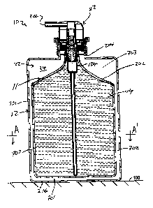
configured to provide
the product 14 with an ethanol concentration between some desired acceptable
range such as
between 75% and 60% during selected periods of time following the initial fill
time, for
example, from the 4th month after filling to the 8th month after filling, or
to have a shelf life
during which the ethanol concentration in the product does not drop below a
desired limit, for
example, 60%.
21
CA 2984761 2017-11-06
[0126] In accordance with a method of the present invention, a large batch
of product 14
may be prepared, for example, of 10,000 liters having a consistent composition
with 70%
ethanol. The product 14 may be filled into the 10,000 separate fluid storage
reservoirs 10 each
having a volume of 1 liter of the product in the first container. 5,000 of the
fluid storage
reservoirs 10 may have the second container filled with the sacrifice material
having 70%
ethanol; 3,000 of the fluid storage reservoirs 10 may be filled with sacrifice
material 24 having
80% ethanol and 2,000 of the fluid storage reservoirs 10 may be filled with
sacrifice material
containing 90% ethanol. Each of the 10,000 reservoirs will be marked with a
marking
indicating a period of time for best use calculated when the ethanol in the
first container is in a
desired range of 70% to 60%. By varying the ethanol concentration in the
sacrifice fluid 24,
the periods of times from initial filling when the product is best for use can
be varied. As
another variation, rather than vary the ethanol concentration of the sacrifice
fluid 24, the
relative volume of the sacrifice fluid 24 can be varied such that with the
provision of a larger
volume of sacrifice fluid 24 in one reservoir 10 compared to another
reservoir, the length of
time after initial filling that reservoir 10 will have a period for best use
which will increase.
Similarly, both the ethanol concentration and the volume of the sacrifice
fluid 24 may be
varied to change the period for best use.
[0127] The desired shelf life of product 14 may be selected, for example,
to be a period of
time such as two years during which the ethanol concentration in the product
will not drop
below a predetermined minimum, for example, 60% by weight and with, for
example, at the
end of the two years, the ethanol concentration dropping from 60% to just
below 60%.
[0128] Reference is made to FIGS. 5 and 6 which illustrate a second
embodiment of a
fluid storage reservoir 10 in accordance with the present invention.
Throughout the Figures,
similar reference numerals are used to refer to similar elements.
[0129] The second embodiment of a fluid storage reservoir 10 of FIGS. 5
and 6 has many
similarities to the first embodiment shown in FIG. 3, however, with a number
of differences.
A first difference is that the bottle 201 is replaced by a fully collapsible
outer bag 201 having
a bag wall 260 formed from a thin flexible material and with an opening of the
outer bag 201
sealed to a radially outer surface of the outer tube 125 of the cap body 115
as by heat welding
22
CA 2984761 2017-11-06
rather than by a threaded connection as was the case with the bottle 201 in
the first
embodiment. A second difference is that the fill tube 217 and its second
closure cap 219 has
been eliminated. A third difference is that the outer bag 210 is provided
proximate its second
end wall 206 remote from the cap body 115 with a fill tube 317 closable by a
threaded second
closure cap 319 with the fill tube 317 having an annular flange 318 heat
sealed to the wall 260
of the outer bag 201 annularly about an opening through the wall of the outer
bag 201. A
fourth difference is that the first closure cap 208 has been eliminated and
replaced by both a
piston-forming element 114 coaxially received within the cylindrical inner
tube 124 and a
one-way inlet valve 332 which foini with the inner tube 124 a piston pump
assembly 112.
[0130] As in the first embodiment in FIGS. 5 and 6, the first container 11
is defined with
an enclosed interior 12 within an enclosing wall member 13 comprising the
inner bag 202,
portions of the inner tube 124 and the one-way valve 333. A second container
21 having an
enclosed interior 22 is defined within an enclosing wall member 23 comprising
the outer bag
201 together with portions of the cap body 115 and portions of the inner bag
202. The first
container 11 is filled with the fluid product 14 to be dispensed containing a
volatile
component. The second container 21 is filled with the sacrifice fluid 24
containing the same
volatile component. In the embodiment of FIGS. 5 and 6, in use to dispense the
product 14
with operation of the pump assembly 112 to draw the fluid product 14 from the
first container
11, the inner bag 202 collapses and with collapse of the inner bag 202, the
outer bag 201 also
collapses. In the embodiment of FIGS. 5 and 6, the walls of outer bag 201 and
the inner bag
202 are formed from flexible thin material such as preferably polyethylene
which readily
collapses when the product 14 is drawn from the inner bag 202.
[0131] Reference is made to FIG. 7 which shows the fluid storage reservoir
10 of the
second embodiment of FIGS. 5 and 6 received within a manually operated hand
cleaner foam
dispenser 600. The dispenser 600 is adapted to removably receive the fluid
storage reservoir
10. The dispenser 600 is shown in side cross-section other than an activating
lever 610 which
is schematically shown in side view and not cross-sectioned. The fluid storage
reservoir 10 is
shown with a lower portion in side view and an upper portion in cross-section.
A user's hand
620 is shown in side view and not in cross-section.
23
CA 2984761 2017-11-06
[0132] The pump assembly 112 includes the piston-forming element 114 and
the inner
tube 124 of the cap body 115. The piston-forming element 114 carries a
discharge outlet 120
to discharge the fluid product 14 as a liquid stream onto the upturned palm
632 and/or fingers
630 of the user's hand 620.
[0133] In FIG. 7, the dispenser 600 includes a back plate 602 as for
mounting of the
dispenser 600 to a building wall 604. A support plate 606 extends forwardly
from the back
plate 604 to support and receive the fluid storage reservoir 10. The support
plate 606 has a
rear portion 607, two side arms 608 (only one of which is seen) and a forward
portion 609.
The side arms 608 extend forwardly from the rear portion 607 to support the
forward portion
609 forming a lower front wall of the dispenser 600. The support plate 606 has
an opening
extending downwardly therethrough defined between the side arms 608 and
between the
forward portion 609 and the rear portion 607 via which opening 612 the fluid
storage reservoir
may be inserted downwardly and then slid rearwardly for secure engagement of
the fluid
storage reservoir 10 on the support plate 606 with an annular engagement
flange 117 on the
cap body 115 of the pump assembly 112 engaged within complementary slots 607
in the
support plate 606 that open into the opening 612.
[0134] The activating lever 610 is journaled to the forward portion 609
for pivoting about
a horizontal axis 614. An upper end of the lever 610 carries a hook 616 to
engage an annular
engagement flange 217 on the piston-forming element 114 of the pump assembly
112 and
couple the lever 610 to the piston-forming element 114 such that by movement
of a lower
handle end of the lever 610 in the direction indicated by the arrow 619
manually by the hand
620 of a user slides the piston-forming element 114 relative the cap body 115
of the pump
assembly 112 upwardly and inwardly in a retraction stroke to the retracted
position shown in
FIG. 5 thereby dispensing the fluid product 14 downwardly onto the user's hand
620. On
release of the lower handle end of the lever 610, a spring 622 biases the
upper end of the lever
610 downwardly so that the lever 610 moves the piston-forming element 114
relative the
piston chamber-forming cap body 115 outwardly in an extension stroke to an
extended
position not shown in FIG. 5.
24
CA 2984761 2017-11-06
[0135] A cover member 624 is hinged at 625 to an upper forward extension
626 of the
back plate 604 so as to permit manual removal and replacement of the fluid
storage reservoir
10.
[0136] FIGS. 5 and 7 show the fluid storage reservoir 10 and its pump
assembly 112 of
FIG. 5 in cross-sectional front view in which the piston-forming element 114
is in a retracted
position relative to the cap body 115.
[0137] The cap body 115 has the end wall 123 supporting both a cylindrical
inner tube
124 and a cylindrical outer tube 125 coaxial about a common central axis 126.
The
cylindrical inner tube 124 extends to an open inner end 127. The cylindrical
outer tube 125
extends from the end wall 123 to an open inner end 128. The annular engagement
flange 117
extends radially outwardly from the cylindrical outer tube 125.
[0138] A liquid chamber 130 is provided within the inner tube 124. At an
inner end of the
liquid chamber 130, an inlet opening 131 is provided in communication with the
fluid product
14 within the first container 11. A one-way liquid valve 332 is disposed
across the inlet
opening 131 to provide for fluid product 14 to flow from the first container
11 into the liquid
chamber 130 yet to prevent fluid product 14 to flow from the liquid chamber
130 to the first
container 11 by reason of the one-way inlet valve 131 carrying a resilient
valve disc 133
which engages a radially inwardly directed inner wall 134 of the inner tube
124.
[0139] The piston-forming element 114 carries a liquid piston 135
coaxially disposed
within the liquid chamber 130. The piston-forming element 114 is coaxially
slidable relative
to the piston chamber-forming body 115 about the axis 126 for movement in a
cycle of
operation including a retraction stroke and an extension stroke. In an
extension stroke, the
liquid piston 135 of the piston-forming element 114 moves from the retracted
position of FIG.
6 axially outwardly to an extended position not shown. In a retraction stroke,
the liquid piston
135 of the piston-forming element 114 moves from the extended position to the
retracted
position of FIG. 6.
[0140] In the extension stroke, axial outward movement of the liquid
piston 135 draws the
fluid product 14 from the first container 11 through the inlet opening 131
past the one-way
valve 333 into the liquid chamber 130. In the retraction stroke, axial inward
movement of the
CA 2984761 2017-11-06
, .
liquid piston 135 forces the fluid product 14 from the liquid chamber 130,
past a flexible inner
disc 136 into an annular space 137 about a hollow piston stem 138 of the
liquid piston 135
between the flexible inner disc 136 and an outer sealing disc 139, through a
radially extending
port 140 into a central passageway 141 within the piston stem 138 to the
discharge outlet 120.
The piston pump assembly 112 operates in an analogous manner to the piston
pumps
disclosed in United States Patent 5,282,552 to Ophardt, issued February 1,
1994, the
disclosure of which is incorporated by reference.
[0141] Reference is made to FIGS. 8 to 12 which show a third
embodiment of a fluid
storage reservoir 10 in accordance with the present invention. The fluid
storage reservoir 10
includes a rigid outer bottle 201 and a flexible inner bag 202. A pump
assembly 112 that
includes both a liquid pump and an air pump is threadably engaged on a
threaded neck of the
rigid bottle 201 and is adapted to draw the product 14 from the bag 210 and
dispense it from
an outlet 120 as a foam of the product 14 mixed with air. The pump assembly
112 is the same
as that disclosed in U.S. Patent Publication US 2017/0266680 to Ophardt et al,
published
September 21, 2017, the disclosure of which is incorporated herein by
reference. The flexible
bag 202 is enclosed but for an opening which is heat sealed about an inner
tube 124 of the
pump assembly 112 that extends downwardly inside the neck 204 of the bottle
201. The
pump assembly 112 has a piston biased to an extended position as shown in FIG.
8 in which
product 14 is prevented from discharge from the first container 11 and in
which flow into or
out of the second container 21 is prevented. After storage, during operation
of the pump
assembly 112 to dispense the product 14 from within the first container 11,
during operation
of the pump assembly 112, a one-way valve mechanism is provided that opens to
relieve any
vacuum created within the second container 21 to avoid creating a vacuum which
would
impede the collapse of the collapsible bag 202. The rigid bottle is adapted to
be self-
supporting on its second end wall 216 as on a support surface 100. As can be
seen in FIGS. 8
and 9, the first container 11 and notably its bag 202 is spaced inwardly from
the wall of the
second container 21 and notably the wall of the rigid bottle 201 with spaces
therebetween
including a space 701 at the bottom between the second end walls of the bag
202 and the
second end wall 216 of the bottle 201, a space 702 between the circumferential
walls of the
26
CA 2984761 2017-11-06
,
bag 202 and the circumferential walls of the bottle 201 and an annular space
703 about the
upper end of the bag 202. Towards ensuring there are spaces provided which
separate the
walls of the bag 202 from the walls of the bottle 201, the rigid bottle 201 is
shown as being
provided with a series of circumferentially spaced, vertically extending
channelways 340in its
circumferential side walls which assist in holding the circumferential walls
of the inner bag
202 spaced inwardly providing vertically extending passageways 341 to receive
and permit
flow of the sacrifice fluid. Similarly, as can be seen in FIGS. 10, 11 and 12,
the second end
wall 216 of the bottle 201 is provided with a flat floor portion 342 from
which a number of
ridges 343 extend upwardly so as to provide, as seen in FIGS. 11 and 12, a
vertical spacing
between the bottom wall of the bag 202 and the second end wall 216 of the
bottle 201.
[0142] Reference is made to FIGS. 13 to 15 which illustrate a fourth
embodiment of a
fluid storage reservoir 10 in accordance with the present invention. As seen
in cross-section
in FIG. 14, a fluid reservoir bottle is formed by a cap 115, an inner bottle
202 and an outer
bottle 201. The inner bottle 202 has an open upper end 450 which is received
in sealed
engagement within a downwardly facing channel 451 in the cap 115. The outer
bottle 201
also has an open upper end 452 which is received in a downwardly opening
groove 453 in an
outer tube 125 of the cap 115. The cap 115 carries a threaded center tube 124.
A pump
assembly 112 is threadably engaged on the threaded center tube 124 and
comprises a piston
pump 114 similar to that described in U.S. Patent 7,815,076 to Ophardt, issued
October 19,
2010 with a one-way vacuum relief valve 455 to permit atmospheric air to enter
the first
container 11 if a sufficient vacuum is created within the interior 12 of the
first container 11. A
removable closure cap 456 is provided that sealably engages annularly about
the cap 115.
The first container 11 is defined within the inner bottle 202, the cap 115 and
the pump
assembly 112. The outer container 21 is defined between the inner bag 201 and
the outer bag
202 closed at an upper end by the body 115. As can be seen in FIG. 15, in
cross-section, an
annular space is provided between the walls of the inner bottle 202 and the
walls of the outer
bottle 201 which annular space 707 forms the second container 21. Each of the
outer bottle
201 and the inner bottle 202 preferably have a resiliency that permits the
reservoir 10 to be
self-supporting on a second end wall 216 of the outer bottle 201, however,
preferably with the
27
CA 2984761 2017-11-06
. .
walls of the outer bottle 201 and the inner bottle being sufficiently
resilient so as to collapse
sufficiently to accommodate the loss of volume in the first container 11 and
the second
container 21 as the volatile component escapes to the atmosphere during a
desired storage
shelf life.
[0143] Reference is made to FIG. 16 which illustrates a small section
of a spacing screen
member 708 made up of criss-crossing rod-like members 709 and 710 which is
adapted to
optionally be placed so as to extend annularly within the annular space
between the inner bag
201 and the outer bag 202 as schematically illustrated in the cross-section of
FIG. 17 towards
assisting in maintaining the space 707 between the outer bottle 201 and the
inner bottle 202 as
is advantageous to have sacrifice liquid 24 maintained consistently throughout
the height of
the first container 11 and second container 21.
[0144] Reference is made to FIG. 18 which shows a fifth embodiment of
a fluid storage
reservoir 10 in accordance with the present invention and which is identical
to the
embodiment illustrated in FIGS. 13 to 15 but for the first exception that a
bellows portion 500
of the circumferential side wall of the outer bottle 201 is formed as a
bellows and a bellows
portion 501 of the circumferential side wall of the inner bag 202 is also
formed as a bellows.
Each bellows portion 500 and 501 is adapted to compress and expand axially to
accommodate
changes in volumes of the first container 11 and the second container 21. The
bellows
portions 500 and 501 permit the outer bottle 201 and the inner bottle 202 to
be formed to be
substantially rigid other than over the bellows portions.
[0145] While the invention has been described with reference to
preferred embodiments,
many modifications and variations will now occur to a person skilled in the
art. For a
definition of the invention, reference is made to the accompanying claims.
28
CA 2984761 2017-11-06