Note: Descriptions are shown in the official language in which they were submitted.
CA 02984885 2017-11-02
a.
MINERAL ORE SLURRY PRETREATMENT METHOD, AND METHOD FOR
MANUFACTURING MINERAL ORE SLURRY
TECHNICAL FIELD
The present invention relates to a method for pre-treating
ore slurry, and more particularly to a method for pre-treating
ore slurry to be provided to a leaching treatment in a
hydrometallurgical process for nickel oxide ore and a method
for manufacturing ore slurry to be provided to the leaching
treatment.
BACKGROUND ART
In recent years, a high pressure acid leaching method
using sulfuric acid has been gathering attention as a
hydrometallurgical process for nickel oxide ore. This method
is different from a dry smelting method that is a general
smelting method for a nickel oxide ore of the related art and
includes a continuous wet step without including dry steps
such as reducing and drying steps. Thus, the method is
advantageous in regard to energy and cost. In addition, the
method is also advantageous in that it is possible to obtain a
sulfide containing nickel (hereinafter, also referred to as
"nickel sulfide"), whose nickel grade is improved to about 50%
by mass (hereinafter, "% by mass" is simply referred to as
The nickel sulfide is precipitated and generated through
processes in which, after washing a leachate obtained by
leaching the nickel oxide ore, by blowing a hydrogen sulfide
15-00200 (SMMF-087)
CA 02984885 2017-11-02
gas thereto, a sulfuration reaction is caused to occur (a
sulfuration step).
In a step for leaching metal from the nickel oxide ore by
such a high temperature pressure acid leaching method
(hereinafter, also simply referred to as "leaching step"),
since impurity elements such as iron, magnesium, manganese,
and aluminum are leached by sulfuric acid in addition to
nickel and cobalt as recovery targets, an excessive amount of -
sulfuric acid is necessary for the treatment.
Further, in the sulfuration step for recovering nickel and
cobalt, nickel and cobalt are selectively recovered as
sulfides, but most of the impurity elements such as iron,
magnesium, manganese, and aluminum leached by the leaching
treatment in a leaching step do not form sulfides and remain
in a barren solution obtained after sulfides are separated. In
order to discharge this barren solution, it is necessary in a
final neutralization step that metal ions remaining in the
barren solution are precipitated and removed by a
neutralization treatment.
Herein, in the final neutralization step, a method is
generally performed in which the pH of the barren solution is
increased to about 5 by adding a limestone slurry to the
barren solution obtained through the sulfuration step so as to
remove iron and aluminum and then the pH is increased to about
9 by adding a slaked lime slurry thereto so as to remove
magnesium and manganese. Therefore, since the necessary amount
(added amount) of the slaked lime slurry is determined
15-00200 (SMMF-087)
3
depending on the amounts of magnesium ions and manganese ions
remaining in the barren solution, a large amount of slaked
lime slurry is needed in a case where the content of magnesium
and the content of manganese in the nickel oxide ore are
large.
Patent Document 1 discloses a technique of providing a
simple and highly efficient smelting method as the entire
process by simplification of a leaching step and a solid-
liquid separation step, reducing the amount of neutralizer
consumed in a neutralization step and the amount of a
precipitate, an efficient method of repeatedly using water,
and the like in a hydrometallurgical process for recovering
nickel from a nickel oxide ore on the basis of high
temperature pressure leaching. However, Patent Document 1 does
not disclose the technical idea for reducing the amount of
sulfuric acid used in the leaching treatment in the leaching
step or reducing the amount of slaked lime used in the
aforementioned final neutralization step. Further, reducing
the amount of an acid or a neutralizer used in the
hydrometallurgy for nickel oxide ore is required to be
performed, as might be expected, with reducing almost no
nickel yield.
Patent Document 1: Japanese Unexamined Patent Application,
Publication No. 2005-350766
CA 2984885 2019-04-18
3a
SUMMARY
Certain exemplary embodiments provide a method for pre-treating
ore slurry to be provided to a leaching treatment in a
hydrometallurgical process for nickel oxide ore, the method
comprising: a first separation step for separating ore slurry into a
coarse particle fraction and a fine particle fraction using at least
one of a hydrocyclone and a density separator in one to three stages
and supplying the fine particle fraction to the leaching treatment; a
second separation step for separating the coarse particle fraction
separated in the first separation step into a heavy specific gravity
fraction and a light specific gravity fraction using at least a spiral
concentrator and supplying the heavy specific gravity fraction to the
leaching treatment; and a vibration sieving step for separating, by a
vibration sieve, the light specific gravity fraction separated in the
second separation step into a fraction on the sieve and a fraction
under the sieve and supplying the fraction under the sieve as ore
slurry to the leaching treatment.
Certain other exemplary embodiments provide a method for
manufacturing ore slurry to be provided to a leaching
treatment in a hydrometallurgical process for nickel oxide ore,
the method comprising: an ore slurry formation step for
obtaining a coarse ore slurry from the nickel oxide ore; a
first separation step for separating the coarse ore slurry
into a coarse particle fraction and a fine particle fraction
using at least one of a hydrocyclone and a density separator
in one to three stages; a second separation step for
separating the coarse particle fraction separated in the first
CA 2984885 2019-04-18
3h
separation step into a heavy specific gravity fraction and a
light specific gravity fraction using at least a spiral
concentrator; a vibration sieving step for separating, by a
vibration sieve, the light specific gravity fraction separated
in the second separation step into a fraction on the sieve and
a fraction under the sieve; and an ore slurry condensation
step for loading the ore slurry of the fine particle fraction
separated in the first separation step, the ore slurry of the
heavy specific gravity fraction separated in the second
separation step, and the ore slurry of the fraction under the
sieve separated in the vibration sieving step into a solid-
liquid separation device and separating and removing moisture
contained in the ore slurry to condense ore components.
DISCLOSURE OF THE INVENTION
Problems to be Solved by the Invention
CA 2984885 2019-04-18
CA 02984885 2017-11-02
4
The present invention is proposed in view of such
circumstances, and an object thereof is to provide a method
capable of effectively reducing the amount of sulfuric acid
used in a leaching step and the amount of a neutralizer such
as slaked lime used in a final neutralization step while
reduction of nickel yield in a hydrometallurgical process for
nickel oxide ore is further effectively suppressed.
Means for Solving the Problems
The present inventors have conducted intensive studies to
solve the aforementioned problems. As a result, the present
inventors have found that by carrying out a specific pre-
treatment on ore slurry to be provided to a leaching treatment
in a leaching step of a hydrometallurgical process for nickel
oxide ore, the amount of agents such as sulfuric acid and
slaked lime used in a smelting process can be reduced while
reduction of nickel yield is suppressed to an extremely low
level, and thus the present invention has been completed. That
is, the present invention provides the following.
(1) A first invention of the present invention is a method
for pre-treating ore slurry to be provided to a leaching
treatment in a hydrometallurgical process for nickel oxide
ore, the method including: a first separation step for
separating ore slurry into a coarse particle fraction and a
fine particle traction using at least one of a hydrocyclone
and a density separator at one to three stages and supplying
the fine particle fraction to the leaching treatment; a second
separation step for separating the coarse particle traction
15-00200 (SMMF-087)
CA 02984885 2017-11-02
separated in the first separation step into a heavy specific
gravity fraction and a light specific gravity fraction using
at least a spiral concentrator and supplying the heavy
specific gravity fraction to the leaching treatment; and a
vibration sieving step for separating, by a vibration sieve,
the light specific gravity fraction separated in the second
separation step into a fraction on the sieve and a fraction
under the sieve and supplying the fraction under the sieve as
ore slurry to the leaching treatment.
(2) A second invention of the present invention is the
method for pre-treating ore slurry in the first invention, in
which a mesh size of the vibration sieve is 300 pm or more.
(3) A third invention of the present invention is the
method for pre-treating ore slurry in the first or second
invention, in which the coarse particle fraction to be
separated in the first separation step is a coarse particle
fraction in which particles having a particle diameter of less
than 45 pm in the ore slurry are 35% by mass or less in a solid
content.
(4) A fourth invention of the present invention is the
method for pre-treating ore slurry in any one of the first to
third inventions, in which the first separation step includes
a classification and separation step for supplying the ore
slurry to the hydrocyclone and subjecting the ore slurry to
classification and separation, and a specific gravity
separation step for supplying an underflow classified by the
hydrocyclone in the classification and separation step to the
15-00200 (SMMF-087)
CA 02984885 2017-11-02
6
density separator and subjecting the underflow to specific
gravity separation.
(5) A fifth invention of the present invention is the
method for pre-treating ore slurry in any one of the first to
fourth inventions, in which the hydrometallurgical process for
nickel oxide ore includes an ore slurry formation step for
forming slurry of the nickel oxide ore (ore slurry), a
leaching step for carrying out a leaching treatment on the ore
slurry under high temperature and high pressure by adding
sulfuric acid, a solid-liquid separation step for separating a
residue while the obtained leached slurry is washed in
multiple stages, to obtain a leachate containing nickel and
impurity elements, a neutralization step for separating a
neutralized precipitate containing the impurity elements by
adjusting a pH of the leachate to obtain a post-neutralization
solution containing nickel, a sulfuration step for carrying
out a sulfuration treatment on the post-neutralization
solution to generate a sulfide containing nickel and a barren
solution, and a final neutralization step for recovering and
detoxifying the barren solution discharged in the sulfuration
step.
(6) A sixth invention of the present invention is a method
for manufacturing ore slurry to be provided to a leaching
treatment in a hydrometallurgical process for nickel oxide
ore, the method including: an ore slurry formation step for
obtaining a coarse ore slurry from the nickel oxide ore; a
first separation step for separating the coarse ore slurry
15-00200 (SMMF-087)
CA 02984885 2017-11-02
7
into a coarse particle fraction and a fine particle fraction
using at least one of a hydrocyclone and a density separator
at one to three stages; a second separation step for
separating the coarse particle fraction separated in the first
separation step into a heavy specific gravity fraction and a
light specific gravity fraction using at least a spiral
concentrator; a vibration sieving step for separating, by a
vibration sieve, the light specific gravity fraction separated
in the second separation step into a fraction on the sieve and
a fraction under the sieve; and an ore slurry condensation
step for loading the ore slurry of the fine particle fraction
separated in the first separation step, the ore slurry of the
heavy specific gravity fraction separated in the second
separation step, and the ore slurry of the fraction under the
sieve separated in the vibration sieving step into a solid-
liquid separation device and separating and removing moisture
contained in the ore slurry to condense ore components.
Effects of the Invention
According to the present invention, it is possible to
effectively reduce the amount of sulfuric acid used in the
leaching step and the amount of a neutralizer such as slaked
lime used in the final neutralization step in the
hydrometallurgical process for nickel oxide ore while
reduction of nickel yield is further effectively suppressed.
BRIEF DESCRIPTION OF THE DRAWINGS
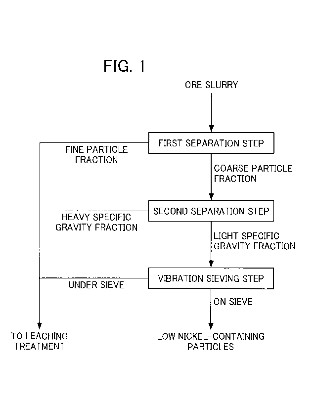
Fig. 1 is a process diagram illustrating an example of the
15-00200 (SMMF-087)
CA 02984885 2017-11-02
8
flow of a method for pre-treating ore slurry. Fig. 2 is a
process diagram illustrating an example of the flow of a
hydrometallurgical process for nickel oxide ore.
PREFERRED MODE FOR CARRYING OUT THE INVENTION
Hereinafter, a specific embodiment of the present
invention (hereinafter, referred to as "the present
embodiment") will be described in detail. Incidentally, the
present invention is not limited to the following embodiment,
and various modifications can be made within the range that
does not change the spirit of the present invention.
<<1. Method for Pre-Treating Ore Slurry>>
The method for pre-treating ore slurry according to the
present embodiment is a method for pre-treating slurry of a
nickel oxide ore to be provided to a leaching treatment, for
example, by high temperature high pressure acid leaching in a
hydrometallurgical process for nickel oxide ore. Specifically,
the method for pre-treating ore slurry includes, as described
in the process diagram illustrated in Fig. 1, a first
separation step for separating ore slurry of nickel oxide ore,
for example, into a coarse particle fraction in which
particles having a particle diameter of less than 45 pm are 35%
by mass or less in a solid content and a fine particle
fraction and supplying the fine particle fraction to the
leaching treatment, a second separation step for subjecting
the separated coarse particle fraction to specific gravity
separation into a heavy specific gravity fraction and a light
15-00200 (SMM F-087)
CA 02984885 2017-11-02
9
specific gravity fraction using a spiral concentrator and
supplying the heavy specific gravity fraction to the leaching
treatment, and a vibration sieving step for separating, by a
vibration sieve, the separated light specific gravity fraction
into a fraction on the sieve and a fraction under the sieve
and supplying the fraction under the sieve as ore slurry to
the leaching treatment.
Herein, it is known that in the hydrometallurgical process
for nickel oxide ore, the amount of sulfuric acid used in the
leaching treatment of a leaching step and the amount of a
neutralizer such as slaked lime used in a neutralization
treatment of a final neutralization step are increased by the
presence of elements such as iron, magnesium, manganese, and
aluminum which are metal elements other than nickel and cobalt
contained in the nickel oxide ore serving as a raw material
ore. Such metal elements are mixed, mainly as gangue
components, in the slurry of the nickel oxide ore (ore slurry)
to be provided to the leaching treatment. The present
inventors found that the gangue components are coarse
particles in the ore slurry, for example, coarse particles
having a particle diameter of 45 Am or more and further exist
as light specific gravity particles.
In this regard, coarse particle ore of the ore slurry to
be provided to the leaching treatment in the leaching step is
separated, light specific gravity particles are further
separated from the coarse particle ore, and then a pre-
treatment to remove the ore of the light specific gravity
15-00200 (SMMF-087)
CA 02984885 2017-11-02
particles by a vibration sieve is carried out. According to
this, it is possible to effectively reduce the amount of
sulfuric acid used in the leaching step and the amount of
slaked lime used in the final neutralization step while
reduction of nickel yield is suppressed to the minimum.
Hereinafter, respective steps will be described.
<1-1. First Separation Step>
In the first separation step, ore slurry of nickel oxide
ore is separated, for example, into a "coarse particle
fraction" in which particles having a particle diameter of
less than 45 pm are 35% by mass or less in a solid content and
a "fine particle fraction." The fine particle fraction
obtained by separation becomes ore slurry to be supplied to
the leaching treatment without any change.
In the first separation step, by using a classification
and separation facility or a specific gravity separation
facility and determining the operation condition thereof, it
is possible to separate the ore slurry into a coarse particle
fraction in which the percentage of particles having a
particle diameter of less than 45 m in the ore slurry is 35%
by mass or less and a fine particle fraction.
More specifically, the separation treatment in the first
separation step is performed by using at least one of a
hydrocyclone and a density separator at one to three stages.
In such a separation treatment using a hydrocyclone or a
density separator, the ore slurry can be separated into an
underflow and an overflow with high accuracy on the basis of
15-00200 (SMMF-087)
CA 02984885 2017-11-02
11
the particle size, which is preferable.
In particular, it is more preferable that in this
separation treatment, first, the ore slurry be supplied to the
hydrocyclone and subjected to classification and separation
(this treatment step is also referred to as the
"classification and separation step"), and then the underflow
classified by the hydrocyclone in the classification and
separation step be supplied to the density separator and
subjected to specific gravity separation (this treatment step
is also referred to as the "specific gravity separation
step").
That is, the amount of the nickel oxide ore (ore slurry)
to be treated in the hydrometallurgical process is large, and
the particles of the ore slurry are, for example, fine
particles in which 80% to 95% of the particles have a particle
diameter of less than 45 Rm. For this reason, in the first
separation step, it is preferable to first carry out a
classification and separation treatment using a hydrocyclone
that is suitable for treating a large amount of the ore slurry
and suitable for treating the fine particle fraction, that is,
treatment in a case where distribution to the overflow is
large.
Subsequently, it is preferable to carry out a specific
gravity separation treatment using a density separator that is
suitable for treatment in a case where the treated amount is
relatively small and the distribution ratios of the underflow
and the overflow are almost the same, to the ore slurry whose
15-00200 (SMMF-087)
CA 02984885 2017-11-02
12
amount to be treated is largely reduced.
Herein, when the percentage of particles having a particle
diameter of less than 45 m in the ore slurry to be provided to
the second separation step to be described later is more than
35% by mass, separation property in the spiral concentrator to
be used in the second separation step deteriorates and thus a
large amount of the particles having a particle diameter of
less than 45 m remain in the light specific gravity fraction
obtained by specific gravity separation. Then, in the
vibration sieving step of the subsequent step, the particles
having a particle diameter of less than 45 m in the light
specific gravity fraction adhere to the low nickel-containing
coarse particles and thus the particles having a particle
diameter of less than 45 ra move on the vibration sieve and are
removed together with the low nickel-containing particles.
On the other hand, although the percentage of particles
having a particle diameter of less than 45 m in the ore slurry
is desirably near 0%, when the percentage of particles having
a particle diameter of less than 45 m is decreased, the low
nickel-containing coarse particles are mixed with the fine
particle fraction separated from the coarse particle fraction
in the first separation step. For examples, when the
percentage of particles having a particle diameter of less
than 45 m is less than 10% by mass, the low nickel-containing
coarse particles start to be mixed with the fine particle
fraction.
<1-2. Second Separation Step>
15-00200 (SMMF-087)
CA 02984885 2017-11-02
13
In the second separation step, the coarse particle
fraction separated in the first separation step in which the
percentage of particles having a particle diameter of less
than 45 m is 35% by mass or less in the ore slurry is supplied
to the spiral concentrator and separated into heavy specific
gravity particles having a heavy specific gravity (also
referred to as "heavy specific gravity fraction") and light
specific gravity particles having a light specific gravity
(also referred to as "light specific gravity fraction"). The
heavy specific gravity fraction obtained by separation becomes
ore slurry to be supplied to the leaching treatment.
Specifically, in this second separation step, specific
gravity separation by the spiral concentrator is performed in
order to selectively remove gangue components having a light
specific gravity in which a ratio of magnesium is larger than
that of nickel. In this way, by separating ore slurry into the
coarse particle fraction and the fine particle fraction using
a hydrocyclone or a density separator and further separating
preferentially gangue components having a light specific
gravity from the separated coarse particle fraction using a
spiral concentrator to be removed, the low nickel-containing
particles containing gangue components in the ore slurry can
be more efficiently separated and removed. According to this,
the amount of sulfuric acid used in the leaching step and the
amount of slaked lime used in the final neutralization step
can be effectively reduced while reduction of nickel yield is
suppressed to an extremely low level.
15-00200 (SMMF-087)
CA 02984885 2017-11-02
14
Incidentally, by supplying the ore slurry to a spiral
concentrator having small installation capacity in a state
where the treated amount is decreased in the aforementioned
first separation step, the number of necessary spiral
concentrators can be decreased.
<1-3. Vibration Sieving Step>
Next, the ore slurry of the light specific gravity
fraction separated in the second separation step is separated,
by using a vibration sieve, into a fraction on the sieve and a
fraction under the sieve and the fraction under the sieve as
ore slurry is supplied to the leaching treatment in the
leaching step. In this way, by carrying out the treatment by
the vibration sieve, the ore particles having a low nickel
grade are separated and the ore particles can be dehydrated.
Thus, a dehydration step or the like is not separately
provided and the ore particles can be deposited without any
change.
The mesh size of the vibration sieve to be used in a
vibration sieving treatment is not particularly limited, but
is preferably set to 300 m or more and more preferably set to
about 300 m to 500 Rm. When the mesh size of the vibration
sieve is less than 300 m, the percentage of ore particles
remaining on the sieve is increased, and in accordance with
this increase, fine particles having a high nickel content
which adhere to the ore particles and remain on the sieve may
be increased. On the other hand, when the mesh size of the
vibration sieve is more than 500 pm, the ore particles having
15-00200 (SMMF-087)
CA 02984885 2017-11-02
a low nickel grade are mixed with the fraction under the sieve
in some cases.
As described above, the method for pre-treating ore slurry
according to the present embodiment includes a first
separation step for separating ore slurry to be provided to a
leaching treatment in a hydrometallurgical process for nickel
oxide ore into a coarse particle fraction in which particles
having a particle diameter of less than 45 imm are 35% by mass
or less in a solid content and a fine particle fraction, a
second separation step for subjecting the separated coarse
particle fraction to specific gravity separation into a heavy
specific gravity fraction and a light specific gravity
fraction using a spiral concentrator, and a vibration sieving
step for performing a sieving treatment on the separated light
specific gravity fraction (also referred to as "light specific
gravity coarse particles") by a vibration sieve.
By performing such a series of pre-treatment, in the
fraction on the vibration sieve obtained through the vibration
sieving step, gangue components such as iron, magnesium,
manganese, and aluminum can be efficiently separated. Then, by
supplying other separated components, that is, the fine
particle fraction separated in the first separation step, the
heavy specific gravity fraction separated in the second
separation step, and the component of the fraction under the
vibration sieve in the vibration sieving step as the ore
slurry to the leaching treatment, the amount of sulfuric acid
used in the leaching step and the amount of a neutralizer such
15-).20D (SMMF-087)
CA 02984885 2017-11-02
16
as slaked lime used in the final neutralization step in the
hydrometallurgical process can be effectively reduced while
reduction of nickel yield is suppressed to extremely low.
Hereinafter, the hydrometallurgical process for nickel
oxide ore to which the method for pre-treating ore slurry is
applied will be described in detail.
<<2. Regarding Hydrometallurgical Process for Nickel Oxide Ore
>>
The hydrometallurgical process for nickel oxide ore is,
for example, a smelting process for leaching nickel to recover
nickel from the nickel oxide ore by using a high pressure acid
leaching method (HPAL method).
Fig. 2 is a process diagram illustrating an example of the
flow of a hydrometallurgical process for nickel oxide ore by a
high pressure acid leaching method. As illustrated in the
process diagram of Fig. 2, the hydrometallurgical process for
nickel oxide ore includes: an ore slurry formation step S1 for
forming the nickel oxide ore as slurry; an ore slurry
condensation step S3 for condensing ore components by removing
moisture contained in the ore slurry; a leaching step S4 for
preforming a leaching treatment under high temperature and
high pressure by adding sulfuric acid to the produced ore
slurry; a solid-liquid separation step 55 for separating a
residue while the obtained leached slurry is washed in
multiple stages to obtain a leachate containing nickel and
impurity elements; a neutralization step S6 for separating a
neutralized precipitate containing impurity elements by
15-00200 (SMMF-087)
CA 02984885 2017-11-02
17
adjusting the pH of the leachate to obtain a post-
neutralization solution containing nickel; and a sulfuration
step S7 for generating a sulfide containing nickel (nickel
sulfide) by adding a sulfurizing agent to the post-
neutralization solution. Furthermore, this hydrometallurgical
process includes a final neutralization step S8 for recovering
and detoxifying the leaching residue separated in the solid-
liquid separation step S5 and a barren solution discharged in
the sulfuration step S7.
Further, in the present embodiment, it is characterized in
that before carrying out the leaching treatment using sulfuric
acid on the ore slurry, a pre-treatment step S2 for pre-
treating the slurried ore is provided.
(1) Ore Slurry Formation Step
In the ore slurry formation step Si, the nickel oxide ore
serving as a raw material ore is classified at a predetermined
classifying point so that oversized ore particles are removed,
and then water is added to undersized ore particles to obtain
a coarse ore slurry.
Herein, the nickel oxide ore serving as a raw material ore
is ore containing nickel and cobalt, and a so-called laterite
ore such as a limonite ore and a saprolite ore is mainly used.
The content of nickel in the laterite ore is typically 0.8% by
weight to 2.5% by weight and nickel is contained as hydroxide
or silica-magnesia (magnesium silicate) mineral. Further, the
content of iron is 10% by weight to 50% by weight and iron is
mainly in the form of trivalent hydroxide (goethite); however,
15-00200 (SMMF-087)
CA 02984885 2017-11-02
18
some divalent iron is contained in silica-magnesia mineral.
Further, in addition to such a laterite ore, an oxide ore
containing valuable metals such as nickel, cobalt, manganese,
and copper, for example, manganese nodules existing at the
bottom of the deep 'Daft of the sea, or the like are used.
The method for classifying the nickel oxide ore is not
particularly limited as long as it can classify ores on the
basis of a desired particle diameter, and for example, the
classification can be performed by sieve classification using
a general grizzly sieve, a vibration sieve, or the like.
Further, the classifying point is not particularly limited,
and a classifying point for obtaining ore slurry composed of
ore particles having a desired particle diameter value or less
can be appropriately set.
(2) Pre-Treatment Step
In the present embodiment, before carrying out the
leaching treatment on the ore slurry, the pre-treatment step
S2 for pre-treating the ore slurry obtained through the ore
slurry formation step S1 is provided.
The pre-treatment step S2 includes a first separation step
S21 for separating the ore slurry obtained through the ore
slurry formation step S1 into a coarse particle fraction in
which particles having a particle diameter of less than 45 pm
are 35% by mass or less in a solid content and a fine particle
fraction, a second separation step S22 for carrying out
specific gravity separation on the coarse particle fraction
separated in the first separation step S21, and a vibration
15-00200 (SMMF-087)
CA 02984885 2017-11-02
19
sieving step S23 for separating, by a vibration sieve, the
separated light specific gravity coarse particles into a
fraction on the sieve and a fraction under the sieve.
A detailed description of the pre-treatment in the pre-
treatment step S2 is not provided herein since the pre-
treatment is the same as described above, but by carrying out
the pre-treatment on the ore slurry in this way, it is
possible to separate gangue components such as iron,
magnesium, manganese, and aluminum from the ore slurry and to
effectively reduce the amount of sulfuric acid used in the
leaching step and the amount of a neutralizer such as slaked
lime used in the final neutralization step while reduction of
nickel yield is suppressed to an extremely low level.
Incidentally, the ore slurry of the fine particle fraction
separated in the first separation step S21 in the pre-
treatment step S2, the ore slurry of the heavy specific
gravity fraction separated in the second separation step S22,
and the ore slurry classified into the fraction under the
sieve in the vibration sieving step S23 are supplied to the
leaching treatment in the leaching step S4 through the ore
slurry condensation step S3 described below.
(3) Ore Slurry Condensation Step
In the ore slurry condensation step S3, the ore slurry of
the fine particle fraction separated in the first separation
step S21 in the aforementioned pre-treatment step S2, the ore
slurry of the heavy specific gravity fraction separated in the
second separation step S22, and the ore slurry containing ore
15-00200 (SMMF-087)
CA 02984885 2017-11-02
particles of the fraction under the sieve separated in the
vibration sieving step S23 are loaded into a solid-liquid
separation device and moisture contained in the coarse ore
slurry is separated and removed to condense ore components,
thereby obtaining the ore slurry. The condensed ore slurry
becomes ore slurry to be provided to the leaching treatment in
the leaching step S4.
Specifically, in the ore slurry condensation step S3, each
ore slurry is loaded, for example, into a solid-liquid
separation device such as a thickener, and the solid
components are precipitated and extracted from the lower
portion of the device, while moisture forming a supernatant is
overflowed from the upper portion of the device; thus, solid-
liquid separation is carried out. Through this solid-liquid
separation treatment, the moisture in the ore slurry is
reduced, and the ore components in the slurry are condensed so
that ore slurry having, for example, a solid concentration of
about 40% by weight is obtained.
Incidentally, as described above, by undergoing the ore
slurry formation step Sl, the pre-treatment step S2 including
the first separation step S21, the second separation step S22,
and the vibration sieving step S23, and the ore slurry
condensation step S3, it is possible to manufacture ore slurry
to be provided to the leaching treatment in the leaching step
S4 described below and the method including these steps can be
defined as a method for manufacturing ore slurry.
(4) Leaching Step
15-00200 (sMMF-087)
CA 02984885 2017-11-02
21
In the leaching step S4, the leaching treatment, for
example, using a high pressure acid leaching method is carried
out on the produced ore slurry. Specifically, sulfuric acid is
added to the ore slurry containing the nickel oxide ore
serving as raw material and the ore slurry is stirred while
being pressurized under a high temperature condition of 220 C
to 280 C, thereby generating a leached slurry composed of a
leachate and a leaching residue.
In the leaching treatment in the leaching step S4, a
leaching reaction represented by the following formulae (i) to
(iii) and a high temperature thermal hydrolysis reaction
represented by the following formulae (iv) and (v) occur so
that leaching of nickel, cobalt, and the like as sulfates and
fixation of the leached iron sulfate as hematite are
performed.
= Leaching Reaction
MO+H2S0.4=MS04+H20 ..(i)
(incidentally, M in the formula represents Ni, Co, Fe, Zn, Cu,
Mg, Cr, Mn, or the like)
2Fe(OH)3+3H2SO4=Fe2(SOL1)3+6H20 ..(ii)
Fe0+H2SO4-4FeSO4+H20 ..(iii)
= High Temperature Thermal Hydrolysis Reaction
2FeSO4+H2SO4+1/207Fe2 (SO4) 3+H20 . . ( iv)
Fe2 (SO4) 3+ 3H70Fe203+ 3H2S 04 . 'V)
Herein, conventionally, an excessive amount is generally
used as the amount of sulfuric acid added in the leaching step
S4. Since impurities such as iron, magnesium, manganese, and
15-00200 (SMMF-087)
CA 02984885 2017-11-02
22
aluminum are contained in the nickel oxide ore in addition to
nickel and cobalt and these impurities are also leached by
sulfuric acid, in order to increase a yield of a recovery
target such as nickel or cobalt, the leaching treatment is
performed by adding an excessive amount of sulfuric acid. On
the other hand, in the present embodiment, a specific pre-
treatment is carried out in the aforementioned pre-treatment
step S2 on the ore slurry to be provided to the leaching
treatment in the leaching step S4 so that the concentration of
impurities contained in the ore slurry can be decreased, and
the added amount of sulfuric acid used in the leaching
treatment can be effectively reduced while reduction of yield
of nickel or the like is suppressed to an extremely low level.
(5) Solid-Liquid Separation Step
In the solid-liquid separation step S5, the leached slurry
is separated into a leachate containing impurity elements in
addition to nickel and cobalt and a leaching residue while the
leached slurry obtained through the leaching step S4 is washed
in multiple stages.
In the solid-liquid separation step 55, for example, the
leached slurry is mixed with a rinsing liquid and then
subjected to the solid-liquid separation treatment by a solid-
liquid separation facility such as a thickener. Specifically,
first, the leached slurry is diluted with the rinsing liquid,
and then the leaching residue in the slurry is condensed as a
precipitate in the thickener. According to this, the remaining
nickel adhered to the leaching residue can be decreased
15-00200 (smmF-087)
CA 02984885 2017-11-02
23
depending on the degree of dilution. Incidentally, the solid-
liquid separation treatment may be performed, for example, by
adding an anionic flocculant.
In the solid-liquid separation step S5, it is preferable
that the solid-liquid separation be carried out while the
leached slurry is washed in multiple stages. As a multiple
washing method, for example, a continuous countercurrent
multi-stage washing method in which the leached slurry is
brought into countercurrent contact with a rinsing liquid can
be used. According to this, the rinsing liquid to be newly
introduced into the system can be reduced and the recovery
rate of nickel and cobalt can be improved to 95% or more. In
addition, the rinsing liquid (rinsing water) is not
particularly limited, but it is preferable to use a liquid
which contains no nickel and has no effect on the step. For
example, as the rinsing liquid, preferably, a barren solution
to be obtained in the sulfuration step S7 of the subsequent
steps can be repeatedly used.
(6) Neutralization Step
In the neutralization step S6, the pH of the leachate
separated in the solid-liquid separation step S5 is adjusted
and a neutralized precipitate containing impurity elements is
separated to thereby obtain a post-neutralization solution
containing nickel and cobalt.
Specifically, in the neutralization step S6, a neutralizer
such as calcium carbonate is added to the leachate while the
oxidation of the separated leachate is suppressed such that
15-00200 (SMMF-087)
CA 02984885 2017-11-02
24
the pH of the post-neutralization solution to be obtained is
adjusted to 4 or less, preferably to 3.0 to 3.5, and more
preferably to 3.1 to 3.2, thereby generating a post-
neutralization solution and a neutralized precipitate slurry
containing trivalent iron, aluminum, and the like as impurity
elements. In the neutralization step S6, the impurities are
removed as the neutralized precipitate in this way and a post-
neutralization solution serving as a mother liquor for
recovering nickel is generated.
(7) Sulfuration Step
In the sulfuration step S7, a sulfurizing agent such as
hydrogen sulfide gas is blown into the post-neutralization
solution serving as a mother liquor for recovering nickel to
cause a sulfuration reaction to occur, thereby generating a
sulfide containing nickel (and cobalt) (hereinafter, also
simply referred to as "nickel sulfide") and a barren solution.
The post-neutralization solution serving as a mother
liquor for recovering nickel is a sulfuric acid solution in
which the impurity components in the leachate are decreased
through the neutralization step S6. Incidentally, there is a
possibility that about several g/L of iron, magnesium,
manganese, and the like are contained as impurity components
in the mother liquor for recovering nickel, but these impurity
components have low stability as a sulfide (as compared to
nickel and cobalt to be recovered) and are not contained in
the nickel sulfide to be generated.
The sulfuration treatment in the sulfuration step S7 is
15-00200 (SMMF-087)
CA 02984885 2017-11-02
executed in a nickel recovery facility. The nickel recovery
facility includes, for example, a sulfuration reaction tank in
which a sulfuration reaction is performed by blowing hydrogen
sulfide gas or the like into the post-neutralization solution
serving as the mother liquor and a solid-liquid separation
tank in which nickel sulfide is separated and recovered from
the post-sulfuration reaction solution. The solid-liquid
separation tank is configured, for example, by a thickener or
the like, and the nickel sulfide that is a precipitate is
separated and recovered from the bottom portion of the
thickener by carrying out a sedimentation and separation
treatment on the slurry containing nickel sulfide and obtained
after the sulfuration reaction. Meanwhile, the aqueous
solution components are overflowed and recovered as a barren
solution. Incidentally, the recovered barren solution is a
solution having an extremely low concentration of valuable
metals such as nickel and contains impurity elements such as
iron, magnesium, and manganese remaining without being
sulfurized. This barren solution is transferred to the final
neutralization step S8 described below and subjected to a
detoxification treatment.
(8) Final Neutralization Step
In the final neutralization step S8, a neutralization
treatment (a detoxification treatment) to adjust the pH to a
predetermined pH range satisfying the discharge standard is
carried out on the barren solution discharged in the
aforementioned sulfuration step S7 which contains impurity
15-00200 (SMMF-087)
CA 02984885 2017-11-02
26
elements such as iron, magnesium, and manganese. In this final
neutralization step S8, it is possible to treat the leaching
residue discharged from the solid-liquid separation treatment
in the solid-liquid separation step S5 together with the
barren solution.
A method for the detoxification treatment in the final
neutralization step SB, that is, a method for adjusting the pH
is not particularly limited, but for example, the pH can be
adjusted to a predetermined range by adding a neutralizer such
as a calcium carbonate (limestone) slurry or a calcium
hydroxide (slaked lime) slurry.
In the final neutralization treatment in the final
neutralization step SB, it is possible to perform a stepwise
neutralization treatment including a neutralization treatment
at the first stage (first final neutralization step S81) using
limestone as a neutralizer and a neutralization treatment at
the second stage (second final neutralization step S82) using
slaked lime as a neutralizer. By performing the stepwise
neutralization treatment in this way, the neutralization
treatment can be performed efficiently and effectively.
Specifically, in the first final neutralization step S81,
the barren solution discharged and recovered from the
sulfuration step S7 and the leaching residue separated in the
solid-liquid separation step S5 are loaded into a
neutralization treatment tank and subjected to a stirring
treatment by adding a limestone slurry. In this first final
neutralization step SB1, by adding the limestone slurry, the
15-00200 (SMMF-087)
CA 02984885 2017-11-02
27
pH of a solution to be treated such as the barren solution is
adjusted to 4 to 5.
Next, in the second final neutralization step S82, the
stirring treatment is carried out on the solution subjected to
the neutralization treatment at the first stage by adding a
limestone slurry, by adding a slaked lime slurry. In this
second final neutralization step S82, by adding the slaked
lime slurry, the pH of the solution to be treated is increased
to 8 to 9.
By performing such a two-stage neutralization treatment, a
neutralization treatment residue is generated and stored in a
tailings dam (a tailings residue). Meanwhile, a solution
obtained after the neutralization treatment satisfies the
discharge standard and is discharged to the outside of the
system.
Herein, in the treatment in the final neutralization step,
the amount of a neutralizer such as slaked lime is determined
according to the amount of impurity element ions such as
magnesium ions and manganese ions remaining in the barren
solution. In the present embodiment, a specific pre-treatment
is carried out in the aforementioned pre-treatment step S2 on
the ore slurry to be provided to the leaching treatment in the
leaching step S4 so that the impurity elements such as
magnesium and manganese contained in the ore slurry can be
reduced. According to this, it is possible to decrease the
concentration of these elements contained in the barren
solution and effectively reduce the amount of a neutralizer
15-00200 (SMMF-087)
CA 02984885 2017-11-02
28
used in the neutralization treatment in the final
neutralization step.
EXAMPLES
Hereinafter, the present invention will be described in
more detail by means of Examples, but the present invention is
not limited to the following Examples at all.
[Example 1]
A hydrometallurgical treatment for nickel oxide ore formed
from the process diagram illustrated in Fig. 2 was performed
in the following manner. That is, first, as a pre-treatment
step for ore slurry, ore slurry obtained by slurrying a nickel
oxide ore having a composition presented in the following
Table I was supplied to a hydrocyclone (manufactured by Salter
Cyclones Ltd., SC1030-P type) to be subjected to a
classification and separation treatment and then the underflow
discharged from the hydrocyclone was supplied to a density
separator (manufactured by CFS Co., Ltd., 6x6 type) to be
subjected to a specific gravity separation treatment.
Incidentally, these steps of the separation treatment are
regarded as the first separation step. By the separation
treatment in this first separation step, ore slurry (coarse
particle fraction) in which the content of particles having a
particle diameter of less than 45 vim in the underflow solid
content of the density separator is 25% by mass was obtained.
[Table 1]
15-00200 (SMMF-087)
CA 02984885 2017-11-02
29
Ni [%] Mg [%] SolidW '415111fi1%l
Nickeloxideore
0.91 1.59 60 890
Next, the ore slurry of the coarse particle fraction
separated through the first separation step was supplied at a
solid concentration of 20% to a spiral concentrator
(manufactured by Autotec Inc.) to be subjected to specific
gravity separation, thereby obtaining ore slurry containing
solid contents which have a nickel grade of 0.86% and a
magnesium grade of 5.34%, as a light specific gravity
fraction. Incidentally, this step of the separation treatment
is regarded as the second separation step.
Next, the ore slurry of the separated light specific
gravity fraction was supplied to a vibration sieve equipped
with a sieve having a mesh size of 300 m (manufactured by
Sizetech, VDS27-6 type) to be subjected to a vibration sieving
treatment. Incidentally, this step of the vibration sieving
treatment is regarded as the vibration sieving step. With this
vibration sieve, solid contents having a nickel grade of 0.91%
and a magnesium grade of 8.40%, that is, low nickel-containing
particles were obtained as a fraction on the sieve. Meanwhile,
the ore slurry of the fraction under the vibration sieve in
the vibration sieving step, the ore slurry of the fine
particle fraction separated in the aforementioned first
separation step, and the ore slurry of the heavy specific
gravity fraction separated in the second separation step were
supplied to the leaching step in which the leaching treatment
15-00200 (SMMF-087)
CA 02984885 2017-11-02
is carried out on the ore.
At this time, the nickel loss rate to the fraction on the
vibration sieve was 3.7%. In addition, the amount of sulfuric
acid consumed in the leaching treatment in the leaching step
to which the ore slurry was supplied was 278 kg/ore tonne.
Further, when the sulfuration treatment was carried out on the
leachate obtained through the leaching treatment (the
sulfuration step) and the final neutralization treatment was
carried out on the barren solution obtained by the sulfuration
treatment (the final neutralization step), the amount of
slaked lime used in the neutralization treatment was 41 kg/ore
tonne.
[Example 21
By performing a similar operation to Example 1, in the
first separation step, ore slurry (coarse particle fraction)
in which the content of particles having a particle diameter
of less than 45 pm in the underflow solid content of the
density separator is 30% by mass was obtained.
Then, for the second separation step, the obtained ore
slurry of the coarse particle fraction was supplied at a solid
concentration of 20% to a spiral concentrator, thereby
obtaining ore slurry containing solid contents which have a
nickel grade of 0.85% and a magnesium grade of 4.99%, as a
light specific gravity fraction.
Further, for the vibration sieving step, the obtained ore
slurry of the light specific gravity fraction was supplied to
a vibration sieve equipped with a sieve having a mesh size of
15-00200 (SMNIF-087)
CA 02984885 2017-11-02
31
300 Ira to be subjected to a vibration sieving treatment. With
this vibration sieve, solid contents having a nickel grade of
0.91% and a magnesium grade of 8.23%, that is, low nickel-
containing particles were obtained as a fraction on the sieve.
Meanwhile, the ore slurry of the fraction under the vibration
sieve in the vibration sieving step, the ore slurry of the
fine particle fraction separated in the aforementioned first
separation step, and the ore slurry of the heavy specific
gravity fraction separated in the second separation step were
supplied to the leaching step in which the leaching treatment
is carried out on the ore.
At this time, the nickel loss rate to the fraction on the
vibration sieve was 3.8%. In addition, the amount of sulfuric
acid consumed in the leaching treatment in the leaching step
to which the ore slurry was supplied was 278 kg/ore tonne.
Further, when the sulfuration treatment was carried out on the
leachate obtained through the leaching treatment (the
sulfuration step) and the final neutralization treatment was
carried out on the barren solution obtained by the sulfuration
treatment (the final neutralization step), the amount of
slaked lime used in the neutralization treatment was 41 kg/ore
tonne.
[Example 3]
By performing a similar operation to Example 1, ore slurry
(coarse particle fraction) in which the content of particles
having a particle diameter of less than 45 m in the underflow
solid content of the density separator is 35% by mass was
15-00200 (smmF-087)
CA 02984885 2017-11-02
32
obtained in the first separation step.
Then, for the second separation step, the obtained ore
slurry of the coarse particle fraction was supplied at a solid
concentration of 20% to a spiral concentrator, thereby
obtaining ore slurry containing solid contents which have a
nickel grade of 0.84% and a magnesium grade of 4.36%, as a
light specific gravity fraction.
Further, for the vibration sieving step, the obtained ore
slurry of the light specific gravity fraction was supplied to
a vibration sieve equipped with a sieve having a mesh size of
300 pm to be subjected to a vibration sieving treatment. With
this vibration sieve, solid contents having a nickel grade of
0.88% and a magnesium grade of 6.77%, that is, low nickel-
containing particles were obtained as a fraction on the sieve.
Meanwhile, the ore slurry of the fraction under the vibration
sieve in the vibration sieving step, the ore slurry of the
fine particle fraction separated in the aforementioned first
separation step, and the ore slurry of the heavy specific
gravity fraction separated in the second separation step were
supplied to the leaching step in which the leaching treatment
is carried out on the ore.
At this time, although the nickel loss rate to the
fraction on the vibration sieve was 4.9% and was slightly
increased as compared to Examples 1 and 2, it was possible to
suppress reduction of nickel yield to a low level.
Incidentally, the reason why the nickel loss rate is increased
as compared to Examples 1 and 2 is considered that since the
15-00200 (SMMF-087)
CA 02984885 2017-11-02
33
content of particles having a particle diameter of less than
45 um in the ore slurry supplied to the spiral concentrator was
slightly large, separation property in the spiral concentrator
slightly deteriorates and particles having a particle diameter
of less than 45 m also moved on the vibration sieve and were
removed together with the low nickel-containing particles.
The amount of sulfuric acid consumed in the leaching
treatment in the leaching step to which the ore slurry was
supplied was 279 kg/ore tonne. Further, when the sulfuration
treatment was carried out on the leachate obtained through the
leaching treatment (the sulfuration step) and the final
neutralization treatment was carried out on the barren
solution obtained by the sulfuration treatment (the final
neutralization step), the amount of slaked lime used in the
neutralization treatment was 40.5 kg/ore tonne.
As described above, in Example 3, although nickel yield
was slightly reduced, it was possible to suppress the amount
of sulfuric acid used in the leaching step and the amount of
slaked lime used in the final neutralization step to low
similarly to Examples 1 and 2.
[Comparative Example 1]
A nickel oxide ore having a composition presented in Table
1 was slurried and a similar operation to Example 1 was
performed to obtain ore slurry (coarse particle fraction) in
which the content of particles having a particle diameter of
less than 45 pm in the unde/flow solid content of the density
separator is 25% by mass was obtained in the first separation
15-00200 (SMMF-087)
CA 02984885 2017-11-02
34
step.
Next, for the vibration sieving step, the obtained ore
slurry of the coarse particle fraction was supplied to a
vibration sieve equipped with a sieve having a mesh size of
300 pm to be subjected to the vibration sieving treatment,
without carrying out the treatment in the spiral concentrator.
With this vibration sieve, solid contents having a nickel
grade of 0.83% and a magnesium grade of 7.50% were obtained as
a fraction on the sieve.
The ore slurry of the fraction under the vibration sieve
in the vibration sieving step and the ore slurry of the fine
particle fraction separated in the aforementioned first
separation step were supplied to the leaching step in which
the leaching treatment is carried out on the ore.
At this time, in Comparative Example 1, the nickel loss
rate to the fraction on the vibration sieve was 6.7%, which
was extremely large. The reason for this is considered that it
was not possible to selectively separate and remove the gangue
components having a light specific gravity since the treatment
by the spiral concentrator was not performed. Incidentally,
the amount of sulfuric acid consumed in the leaching treatment
in the leaching step to which the ore slurry was supplied was
272 kg/ore tonne. Further, when the sulfuration treatment was
carried out on the leachate obtained through the leaching
treatment (the sulfuration step) and the final neutralization
treatment was carried out on the barren solution obtained by
the sulfuration treatment (the final neutralization step), the
15-00200 (SMMF-087)
CA 02984885 2017-11-02
amount of slaked lime used in the neutralization treatment was
36.0 kg/ore tonne.
As described above, in Comparative Example 1, the amount
of sulfuric acid used in the leaching step and the amount of
slaked lime used in the final neutralization step could be
reduced, but the nickel yield was decreased.
[Comparative Example 2]
A nickel oxide ore having a composition presented in Table
I was slurried and a similar operation to Example I was
performed to obtain ore slurry (coarse particle fraction) in
which the content of particles having a particle diameter of
less than 45 pm in the underflow solid content of the density
separator is 30% by mass was obtained in the first separation
step.
Next, for the vibration sieving step, the obtained ore
slurry of the coarse particle fraction was supplied to a
vibration sieve equipped with a sieve having a mesh size of
300 m to be subjected to the vibration sieving treatment,
without carrying out the treatment in the spiral concentrator.
With this vibration sieve, solid contents having a nickel
grade of 0.84% and a magnesium grade of 7.39% were obtained as
a fraction on the sieve.
The ore slurry of the fraction under the vibration sieve
in the vibration sieving step and the ore slurry of the fine
particle fraction separated in the aforementioned first
separation step were supplied to the leaching step in which
the leaching treatment is carried out on the ore.
15-00200 (SMMF-087)
CA 02984885 2017-11-02
36
At this time, in Comparative Example 2, the nickel loss
rate to the fraction on the vibration sieve was 6.8%, which
was extremely large. Incidentally, the amount of sulfuric acid
consumed in the leaching treatment in the leaching step to
which the ore slurry was supplied was 272 kg/ore tonne.
Further, when the sulfuration treatment was carried out on the
leachate obtained through the leaching treatment (the
sulfuration step) and the final neutralization treatment was
carried out on the barren solution obtained by the sulfuration
treatment (the final neutralization step), the amount of
slaked lime used in the neutralization treatment was 36.0
kg/ore tonne.
As described above, in Comparative Example 2, the amount
of sulfuric acid used in the leaching step and the amount of
slaked lime used in the final neutralization step could be
reduced, but the nickel yield was decreased.
[Comparative Example 3]
A nickel oxide ore having a composition presented in Table
I was slurried and the ore slurry was supplied to the leaching
step in which the leaching treatment is carried out, without
carrying out the pre-treatment (the first separation step, the
second separation step, and the vibration sieving step) on the
ore slurry.
The amount of sulfuric acid consumed in the leaching
treatment in the leaching step to which the ore slurry was
supplied was 287 kg/ore tonne. In addition, when the
sulfuration treatment was carried out on the leachate obtained
15-00200 (SMMF-087)
CA 02984885 2017-11-02
37
through the leaching treatment (the sulfuration step) and the
final neutralization treatment was carried out on the barren
solution obtained by the sulfuration treatment (the final
neutralization step), the amount of slaked lime used in the
neutralization treatment was 47.5 kg/ore tonne.
As described above, in Comparative Example 3, the amount
of sulfuric acid used in the leaching step and the amount of
slaked lime used in the final neutralization step were
increased, and thus it was not possible to effectively reduce
the used amounts thereof.
In the following Table 2, the grades of nickel and
magnesium and the content of particles having a particles
diameter of less than 45 m in the solid content, and the
nickel loss rate of the ore slurry supplied to the spiral
concentrator and the vibration sieve and the recovery
particles recovered on the sieve by the treatment using the
vibration sieve in the operations of Examples 1 to 3 and
Comparative Examples 1 to 3 are collectively presented.
[Table 2]
Slum/who:I Slurry supplied
RecmuyparfidesmmvenA Ni
to spiral concentrator to vibration sieve on the sieve loss
Ni Mg Solid <45pm Ni Mg Solid <45 m M Mg Sold ,451,1m rate
N N N N N 101 N N 11 r
rq
Example 1 0.85 532 92 25.0 0.86 534 53 29.5 0.91
8A 224 2.1 3.7
Example 2 0.85 5.02 9.8 30.0 0.85 4.99 5.8 35.0
0.91 823 229 4.4 3.8
Example 3 0.86 4.73 10.6 35.0 0.84 436 6.8 45.0
0.88 6.77 3.03 202 4.9
Comparative
- 0.85 532 92 25.0 0.83 7.50 434 1.6 6.7
Example 1
Comparative
- 0.85 5.02 9.8 30.0 0.84 739 4.42 33 6.8
Example 2
Comparative
OD
Example 3
15-00200 (SMMF-087)
CA 02984885 2017-11-02
38
Further, in the following Table 3, the amount of sulfuric
acid consumed in the leaching step and the amount of slaked
lime consumed in the final neutralization step in the
operations of Examples 1 to 3 and Comparative Examples 1 to 3
are collectively presented.
[Table 3]
Amount of
Shiny supplied to leaching step Amount of acid
slaked lime
consumed
Consumed
Ni [%] Mg [%] Solid [t/h] [kg/Ore tonne]
[kg/Ore tonne]
Example 1 0.91 132 57.8 278 41.0
Example 2 0.91 1.32 57.7 278 41.0
Example 3 0.91 131 57.0 279 40.5
Comparative
0.91 1.13 55.7 272 36.0
Example 1
Comparative
0.91 1.13 55.6 272 36.0
Example 2
_
Comparative
0.91 1.59 60.0 287 47.5
Example 3
15-00200 (SMM F-087)