Note: Descriptions are shown in the official language in which they were submitted.
DEVICE FOR THE DELIVERY OF A PROSTHETIC IMPLANT AND METHOD OF
USE THEREOF
COPYRIGHT NOTICE
[0001] A portion of the disclosure of this patent document contains
material, which is
subject to copyright protection. The copyright owner has no objection to the
facsimile
reproduction by anyone of the patent document or the patent disclosure, as it
appears in the
Patent and Trademark Office patent files or records, but otherwise reserves
all copyright rights
whatsoever.
FIELD OF THE INVENTION
[0002] The invention described herein generally relates to devices to
assist in the
placement of prosthetic implants. The invention further relates to a device
that hold a prosthetic
implant within a structure that is (or is generally) in the shape of a conical
frustum with an
opening, the interior of which comprises a lubricious coating and is of
suitable dimensions to
hold the prosthetic implant. The application of pressure laterally along the
length of the frustum
ejects the prosthetic implant through the opening and into a surgical pocket
that a surgeon opens
in the body of a patient.
BACKGROUND OF THE INVENTION
100031 Prosthetic implants, in particular breast implants, have a
substantial history dating
back to the first recorded implant surgery done in 1895 at the University of
Heidelberg,
Germany. Instead of being for cosmetic purposes, the physician (Dr. Vincent
Czerny) performed
the procedure by taking fat from the hip of a female for implantation into her
breast, which
needed reconstruction after the removal of an adenoma. Accordingly, the
purpose of this first
"implant" was to reconstruct a breast after devastating surgery, rather than
to achieve uniform
enlargement.
1
CA 2985220 2017-11-14
[0004] The first real foreign substance injected into body to achieve
enlargement is
perhaps the injection of paraffin, which comes in a plurality of textures and
is primarily
composed of petroleum jelly. Dr. Robert Gesurny, an Austrian surgeon who used
the material on
the testicle of a soldier in an attempt to achieve a more desirable size,
first discovered the use of
paraffin for boosting the size of bodily objects. Inspired by the results, Dr.
Gesurny went on to
use the material for breast enlargement injections, universally resulting is
severely compromised
outcomes.
[0005] Modern silicone gel implants, which are well known to those of
ordinary skill in
the art today, have a long history that dates back over the past seventy
years. In fact, some
evidence supports Japanese prostitutes after World War 11 injecting their
breasts with various
substances, including liquid silicone. The serious worry with silicone in
liquid form was that it
broke apart, forming granulomas that could then migrate basically anywhere in
the body. Liquid
silicone is still used, but very rarely, in microscopic amounts, and only
using medical-grade
silicone that is completely sterile; it remains highly controversial and is
associated with serious
complications. Breast implants as presently known in the art ¨ silicone as a
cohesive mass
inside of a polymer "bag" structure ¨ had their debut in the 1960s, developed
by Doctor
Thomas Cronin and his colleague Frank Gerow.
[00061 Although removed from the market for a number of years due to a
variety of
concerns and complications, silicone was allowed back into breast implants in
2006, albeit in a
new form. The FDA, after years of study and experiments, finally allowed
silicone gel-filled
implants onto the U.S. market, which are the sole breast implant option
outside of saline.
Today's silicone gel is designed to feel a bit like human fat: very thick,
very sticky, and classified
as "semi-solid". Such technology actually represents the fifth generation of
silicone implant: the
2
CA 2985220 2017-11-14
first one developed by Cronin and Gerow, with various innovations, including
more secure
coatings, thicker gels and more natural shapes.
[0007] When any type of implant is inserted into a surgical pocket that a
surgeon opens
in the body of a patient, the body reacts by forming a protective lining
around the prosthetic.
This biological structure is referred to as the "capsule", "tissue capsule" or
"scar capsule",
though it should be noted that the structure it is not exactly the same as
scar tissue. Although a
capsule formation is normal and happens regardless of whether the implant is
smooth or
textured, silicone or saline, some theorize that problematic capsule growth is
potentially
attributed to manipulation of tissue during implant placement. In addition,
trauma to tissue along
or adjacent to the surgical pocket may suffer from the direct formation of
scar tissue due to
potentially over aggressive manipulation of tissue at the entry site for the
implant along the edge
of the surgical pocket.
[0008] Accordingly, what is needed in the art are new devices that allow
for the
placement of a prosthetic implant while avoiding the unnecessary manipulation
of tissue adjacent
to or inside a surgical pocket to minimize the development of scar tissue and
the formation of
any significant capsule around the prosthetic implant.
SUMMARY OF THE INVENTION
[0009] Embodiments of the invention are directed towards a surgical
device for assisting
in the placement of a prosthetic implant within a surgical pocket of a
patient. According to one
embodiment, the surgical device comprises a bag shaped as a conical frustum in
which a
proximal end of the conical frustum is sealed and a distal end of the conical
frustum is open. An
elongated slit extends from the distal end towards the proximal end with a
single opening formed
3
CA 2985220 2017-11-14
by the distal opening and the elongated slit being sufficiently large enough
to accept the
prosthetic implant into the bag.
[0010] An adhesive is applied to or otherwise affixed along a portion of
the elongated slit
to seal the elongated slit such that the distal end remains open to allow for
egress of the implant
from the bag for placement into the surgical pocket. The elongated slit may
further comprise a
flap, with the adhesive affixed along the flap. While application of the
adhesive may be along
the entirety of the elongated slit, other embodiments apply or otherwise affix
adhesive along one
or more portions of the elongated slit. Sealing the elongated slit in certain
embodiments allows
for the formation a ridge that provides a support guide for the prosthetic
implant during
placement into the surgical pocket. The configuration of the surgical device
of the present
invention allows the device to accept and place of a variety of prosthetic
implant types including,
but not limited to, a breast implant, a pectoral implant, a calf implant and a
gluteal implant.
100111 The inside surface of the bag is treated or otherwise coated with
a lubricious
coating that, in addition to other benefits, allows the implant to freely exit
the bag. While certain
embodiments utilize a water activated lubricious coating on the interior of
the bag, the lubricious
coating is more generally any hydrophilic gel that decreases the coefficient
of friction of the
inside surface of the bag. According to one embodiment, the bag is composed of
a polymer
selected from the set of polymers consisting of medical grade vinyl, medical
grade PVC, medical
grade nylon and polyethylene. When utilizing medical grade vinyl in the
construction of the bag,
various embodiments utilize medical grade vinyl that is between .01 inches and
.005 inches
thick.
[0012] The outside of the bag may comprise a number of different markings
or indicia
that aid the surgeon in properly placing the prosthetic implant within the
surgical pocket. For
4
CA 2985220 2017-11-14
example, the bag may comprise a marker, such as a circular marker, which
allows the surgeon to
achieve proper alignment of the prosthetic implant during placement into the
surgical pocket.
Application of the marker may be in accordance with any number of processes
that do not affect
the integrity of the material forming the bag, such as a silkscreen process.
The bag may also
have a plurality of size guide lines set at varying distances from the opening
in at the distal end
of the bag. The surgeon can use the plurality of size guide lines to properly
align a cutting
device to excise excess material from the distal opening of the bag.
[0013] The lubricious coating on the inside surface of the bag is
activated by exposure to
water, thereby resulting in a decrease in the coefficient of friction of the
inside surface of the
bag. Activation of the lubricious coating may be through injection of water
into the interior of
the bag through the use of a syringe, or aqueous submersion of the bag.
Alternatively, the
surgeon or technician exposes a sheet of absorbable material placed within the
bag to water,
thereby allowing water to wick through the absorbable material and activate a
lubricious coating
on an inside surface of the bag. According to one embodiment, the sheet of
absorbable material
changes color when exposed to water.
[0014] Beyond the foregoing, embodiments of the present invention are
directed towards
a surgical device for assisting in the placement of a prosthetic implant
within a surgical pocket of
a patient. The surgical device according to the present embodiment comprises a
bag shaped as a
conical frustum in which a proximal end of the conical frustum is sealed and
the distal end of the
conical frustum is open with an elongated slit extending from the distal end
towards the proximal
end. As with other embodiments, an opening formed by the distal opening and
the elongated slit
is sufficiently large enough to accept the prosthetic implant into the bag. An
adhesive along a
portion of the elongated slit can seal the elongated slit such that the distal
end remains open to
CA 2985220 2017-11-14
allow for egress of the implant from the bag for placement into the surgical
pocket. Finally, a
sheet of absorbable material is disposed of within the bag that when exposed
to water allows the
water to wick through the absorbable material and activate a lubricious
coating on an inside
surface of the bag.
100151 Still further, embodiments are directed towards a surgical device
for assisting in
the placement of a prosthetic implant within a surgical pocket of a patient.
The device in
accordance with the present embodiment comprises a bag shaped as a conical
frustum in which a
proximal end of the conical frustum is sealed and the distal end of the
conical frustum is open
with an elongated slit extending from the distal end towards the proximal end.
The distal
opening and the elongated slit form a single opening that is sufficiently
large enough to accept
the prosthetic implant into the bag. A set of inter-lockable fastener elements
disposed along
opposing portions of the elongated slit seal the elongated slit such that the
distal end remains
open to allow for egress of the implant from the bag for placement into the
surgical pocket.
BRIEF DESCRIPTION OF THE DRAWINGS
[0016] The invention is illustrated in the figures of the accompanying
drawings which are
meant to be exemplary and not limiting, in which like references are intended
to refer to like or
corresponding parts, and in which:
100171 Fig. 1 illustrates a top perspective view of a surgical device for
assisting in the
placement of a prosthetic implant within a surgical pocket of a patient
according to one
embodiment of the present invention;
[0018] Fig. 2A illustrates a top perspective view of a surgical device
for assisting in the
placement of a prosthetic implant within a surgical pocket of a patient in
conjunction with a
prosthetic implant according to one embodiment of the present invention;
6
CA 2985220 2017-11-14
[0019] Fig. 2B illustrates the surgical device of Fig. 2A with an implant
seated with the
surgical device and a partially exposed adhesive strip according to one
embodiment of the
present invention;
[0020] Fig. 2C illustrates the surgical device of Fig. 2A with the
elongated slit sealed
such that the distal end remains open to allow for egress of the implant from
the bag for
placement into the surgical pocket according to one embodiment of the present
invention;
[0021] Fig. 3 illustrates several exemplary prior art prosthetic
implants;
[0022] Figs. 4A and 4B illustrate manipulation of a prosthetic implant
through a surgical
device for assisting in the placement of the prosthetic implant within a
surgical pocket of a
patient according to one embodiment of the present invention;
[0023] Figs. 5A and 5B illustrate placement of a prosthetic implant
through a surgical
device for assisting in the placement of the prosthetic implant within a
surgical pocket of a
patient according to one embodiment of the present invention;
[0024] Figs. 6A-6C illustrate a surgical device for assisting in the
placement of the
prosthetic implant within a surgical pocket that utilizes inter-lockable
fastener elements in a first
configuration on a pair fastener strips on each side of an elongated slit
according to a one
embodiment of the invention;
[0025] Figs. 7A-7C illustrate a surgical device for assisting in the
placement of the
prosthetic implant within a surgical pocket that utilizes inter-lockable
fastener elements in a
second configuration on a pair fastener strips on each side of an elongated
slit according to a one
embodiment of the invention; and
7
CA 2985220 2017-11-14
[0026] Fig. 8 illustrates a cross-sectional view of inter-lockable
fastener elements
positioned along the edges of the elongated slit and a locking slider in
accordance with one
embodiment of the present invention.
DETAILED DESCRIPTION OF THE INVENTION
[0027] Subject matter will now be described more fully hereinafter with
reference to the
accompanying drawings, which form a part hereof, and which show, by way of
illustration,
exemplary embodiments in which the invention may be practiced. Subject matter
may, however,
be embodied in a variety of different forms and, therefore, covered or claimed
subject matter is
intended to be construed as not being limited to any example embodiments set
forth herein;
example embodiments are provided merely to be illustrative. Those of skill in
the art understand
that other embodiments may be utilized and structural changes may be made
without departing
from the scope of the present invention. Likewise, a reasonably broad scope
for claimed or
covered subject matter is intended. The following detailed description is,
therefore, not intended
to be taken in a limiting sense.
[0028] Throughout the specification and claims, terms may have nuanced
meanings
suggested or implied in context beyond an explicitly stated meaning. Likewise,
the phrase "in
one embodiment" as used herein does not necessarily refer to the same
embodiment and the
phrase "in another embodiment" as used herein does not necessarily refer to a
different
embodiment. It is intended, for example, that claimed subject matter include
combinations of
example embodiments in whole or in part.
[0029] Fig. 1 illustrates a top perspective view of a surgical device 100
for assisting in
the placement of a prosthetic implant within a surgical pocket of a patient
according to one
embodiment of the present invention. The surgical device 100 comprises a bag
shaped as a
8
CA 2985220 2017-11-14
conical frustum in which a proximal end 112 of the conical frustum is sealed
and a distal end of
the conical frustum is open 104 with an elongated slit 114 extending from the
distal end towards
the proximal end 112. According to one embodiment, the proximal end of the bag
100 is sealed
with an RF weld. The bag 100 may be formed from a single sheet of material
that is stamped or
cut using a die or other suitable technique and folded around itself, or may
be formed by multiple
panels, e.g., front and back panels, that are joined together.
100301 The opening 104 formed by the distal opening and the elongated
slit 114 is of
sufficiently large size to accept a prosthetic implant into the bag.
Accordingly, manufacture of
the surgical device 100 may comprise production of the surgical device in
various sizes or
volumes to accommodate prosthetic implants of various sizes. For example, the
surgical device
100 may be sized differently to accommodate a gluteal implant as opposed to a
breast or calf
implant. According to one embodiment, the bag is of sufficient capacity to
seat the prosthetic
implant and activate the adhesive to allow the elongated slit to be sealed
with the bag horizontal
relative to a standing surgeon.
[00311 A technician preparing the surgical device 100 for use on a
patient places the
implant within the device and seals the elongated slit such that the distal
end remains open to
allow for egress of the implant from the bag and placement into the surgical
pocket. According
to the embodiment of Fig. 1, a flap 106 is formed along one side of the
elongated slit 114 such
that a technician can fold the flap 106 over the elongated slit 114 to form
the seal. An adhesive
108 or other fastening member may be affixed along a portion of the elongated
slit (which may
be on the flap if present) to form a seal such that the distal end remains
open to allow for egress
of the implant from the bag for placement into the surgical pocket.
Advantageously, a ridge
9
CA 2985220 2017-11-14
formed by the sealed elongated slit provides a support guide for the
prosthetic implant during
placement into the surgical pocket.
[0032] The inside surface of the surgical device 100, which is a bag in
the form of a
conical frustum, is treated with a lubricious coating. Lubricity is a property
that describes how
slippery a surface is, more specifically, the value of its coefficient of
friction. Embodiments of
the present invention benefit from this type of slippery surface treatment
because it reduces the
insertion force that the surgeon must apply to propel or eject the prosthetic
implant through the
distal opening in the bag, avoiding possible puncture damage to the prosthetic
implant and severe
abrasion between the implant surface and the interior surface of the bag.
100331 The lubricious coating can be applied to interior surface of the
bag 100 in a
number of ways. One application technique is dip coating, which entails
suspending the bag from
a support, lowering it into a liquid coating solution and then withdrawing.
The coating sticks to
the surface as the support draws the bag up and out of the solution. An
alternative is spray
coating, which is akin to airbrushing and involves spraying a nebulized mist
over the interior
surface of the bag. Film coating is another type of application process in
which long rolls of
material that form the bag are drawn from reel to reel through a tank of
liquid coating. Other
processes for the application of the lubricious coating include chemical vapor
deposition and silk
screening, which is primarily suitable when working with flat surfaces, such
as the raw material
that forms the bag.
[0034] Any of the above-described coating techniques involves a drying or
curing
process to permanently affix the lubricious coating to the interior surface of
the bag. Two
prevalent methods for curing hydrophilic coatings are heat and ultraviolet
("UV") light. When
utilizing heat-cured coatings, the bag is placed within an oven for a given
period of time. Such
CA 2985220 2017-11-14
controlled heating accelerates drying of the coating and any necessary
chemical reactions taking
place within the coating (or between the coating and the bag), such as
crosslinking, which allow
the coating to stick to the interior surface of the bag, as well as provide
durability. For
embodiments that utilize lubricious coatings that use UV light for the curing
step, the interior
surface of the bag is exposed to UV light for a given period of time, which
has the effect of
stimulating any necessary chemical reactions for curing. Completion of the
curing process
affixes the lubricious coating to the interior surface of the bag.
[0035] The lubricious coating is hydrophilic. Hydrophilic coatings
exhibit so-called
"water loving" characteristics. From a chemical perspective, these coatings
participate in
dynamic hydrogen bonding with surrounding water. In some cases, hydrophilic
coatings are also
ionic, and may further exhibit negative charge, which facilitates additional
aqueous interactions.
Physically, these chemical interactions with water give rise to hydrogel
materials that may
exhibit extremely low coefficients of friction. Taken together, these chemical
and physical
characteristics describe a class of materials that are wettable, lubricious,
and suitable for tailored
biological interactions.
[0036] A technician may hydrate the interior of the bag 100 to activate
the lubricious
coating by injecting water into the bag through the use of a syringe 116.
Alternatively, or in
conjunction with the foregoing, the technician may hydrate a polymer insert
(not pictured) placed
within the interior of the bag 100. When hydrating the polymer insert, the
insert serves to wick
the fluid throughout the interior of the bag, thereby activating the
lubricious coating. The
polymer insert is preferably sized to follow the contours of the interior of
the bag 100 and may
comprise any material that suitably wicks fluid throughout its surface
including, but not limited
11
CA 2985220 2017-11-14
to Lightweight Stabilizer (60% polyester/40% Rayon), Medium Weight Stabilizer
(60%
polyester/40% Rayon) and medium to heavyweight sew-in interfacing (100%
Polyester).
[0037] Different markings on the exterior of the bag 100 assist the
technician in
preparing the bag for implant delivery and the surgeon in the delivery
process. For example, a
marker 110 on the outside of the bag allows the technician to align the
prosthetic implant
properly in the bag 100, such as by aligning the marker with a physical marker
on the bottom of
the implant. In this manner, the surgeon is aware of the bottom position of
the implant upon
delivery and can ensure that the implant is not delivered into the surgical
pocket bottom side up.
Application of the marker to the bag is in accordance with any process that
permanently deposits
the marker on the outer surface of the bag without harming or otherwise
causing any degradation
to the bag itself, e.g., through a silkscreen process, inkjet printing or hand
application with
suitable pens or markers. The exterior of the bag 100 may further comprise a
plurality of size
guide lines to properly align a cutting device when excising material from the
distal opening of
the bag. Excising material from the distal opening of the bag allows the
technician to increase
the aperture diameter of the distal opening, thereby allowing the device to
accommodate larger
implant sizes without causing damage to the opening 104 at the distal end of
the bag 100.
[0038] Figs. 2A-2C illustrate placement of an implant into and the
sealing of a surgical
device for assisting in the placement of the prosthetic implant within a
surgical pocket of a
patient. Turning to Fig. 2A, the bag 200 is set out to allow for loading of
the prosthetic implant
202 into the interior of the bag 200. The distal opening 204 and elongated
slit are sized to
accommodate placement of the prosthetic implant 202 into the bag 200 and
further align a
marker on the implant with the marker on the bag 200, thereby providing the
surgeon with an
indication as to the orientation of the implant within the bag. According to
the embodiment that
12
CA 2985220 2017-11-14
Figs. 2A-2C illustrate, a flap 208 is formed along one side of the elongated
slit and covered by an
adhesive backing 210 that covers an underlying adhesive until such a time as
when the
technician is ready to seal the elongated slit.
[0039] Continuing with Fig. 2B, the implant 202 is seated within the
interior of the bag
200. Advantageously, the technician aligns a physical marker on the implant
with the marker on
the outside of the bag. Accordingly, the surgeon has an indication as to the
orientation of the
implant 202 within the bag and can maintain such orientation for the duration
of the implant's
movement through the bag and into a surgical pocket that the surgeon prepares
to accept the
implant. The technician seals the elongated slit, thereby maintaining the
opening in the distal
end of the bag, which the technician may further trim to increase the aperture
of the opening
when placing implants of various sizes. According to the present embodiment,
an adhesive is
applied to a flap that runs along one edge of the elongated slit.
[0040] The technician removes an adhesive backing 210 to expose an
underlying
adhesive 212 that seals the elongated slit by adhesing the flap to the
exterior surface of the bag.
Fig. 2C illustrates the surgical device with the elongated slit sealed such
that the distal end 216
remains open to allow for egress of the implant 202 from the bag 200 for
placement into the
surgical pocket. As can be seen, the flap 214 is folded over and adhesed to
the outside surface of
the bag 200, leaving the distal opening 216 for placement in the surgical
pocket during delivery
of the implant 202.
[0041] Fig. 3 presents a number of prior art implants that are suitable
for use with
embodiments of the present invention. For example, breast 302, gluteal 308 and
various calf
implants 304 and 306, may be set or otherwise placed through use of various
embodiments.
Those of skill in the art recognize that certain aspects of the bag geometry
might require slight
13
CA 2985220 2017-11-14
modification from the illustrations presented in conjunction with the
embodiments depicted
herein. By way of example and not limitation, when placing a gluteal implant
308, which is
typically of a larger volume than a breast implant 302, the length of the bag,
as well as possibly
the angle at which the distal opening forms, may require commensurate
increases.
[0042] As Figs. 4A and 4B illustrate, the implant is set within the bag
402 and the
elongated slit 408 sealed such that sequential application of pressure by the
hands 404 and 406 of
the physician serve to manipulate the implant 412 out through the opening 410
in the distal end
of the bag 402. As described above and further herein in connection with
various embodiments
of the invention, the implant is set and can further be aligned with a marker
on the bag to
understand alignment of the implant as the surgeon manipulates the implant
along the length of
the bag 402. Figs. 4A and 4B illustrate the application of a twisting motion
or the sequential
application of pressure laterally along the bag by the hands of the surgeon
404 and 406, typically
with the proximate hand 406 applying pressure while the distal hand 404
provides support,
although other hand and pressure application configurations fall within the
scope of the
invention. The application of pressure as such serves to drive the implant out
the distal opening
410 and into a surgical pocket that the surgeon has prepared to accept the
implant.
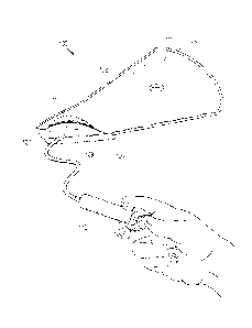
[0043] Figs. 5A and 5B continue the process illustrated by Figs. 4A and
4B in which the
implant is set into a surgical pocket 502 in the body 506 of a patient. The
surgeon or a
technician can utilize a surgical retractor 504 to manipulate the surgical
pocket 502 and properly
position the surgical pocket to receive the implant. For example, a technician
utilizes the surgical
retractor 504 to hold open the surgical pocket 502 that the surgeon incises in
the body 506 of the
patient, such as under the breast. The surgeon, using the implant set in the
bag with the
elongated slit sealed 508, introduces the distal end of the bag into the open
surgical pocket 502.
14
CA 2985220 2017-11-14
Because activated lubricious coating on the interior of the bag greatly
reduces the coefficient of
friction on the interior surface of the bag, manipulation by the surgeon
allows the implant to be
easily driven into the surgical pocket 502 with little disruption or
unnecessary trauma to the
surgical pocket 502 or surrounding tissues. Once the surgeon sets the implant
into the surgical
pocket, he or she removes the bag 508 and the wound is closed through the
application of
sutures, staples, glue or other techniques known to those of skill in the art
suitable to close the
surgical pocket.
[0044] As described above, embodiments of the invention may utilize
various techniques
for affixing the edges of the elongated slit to seal the elongated slit such
that the distal end of the
bag remains open to allow for egress of the implant from the bag. Although
above-described
embodiments illustrate the use of adhesives, other structures such re-closable
fasteners or other
adhesion or fastening techniques known to those of skill in the art may
readily be utilized with
the device.
[0045] Figs. 6A-6C illustrate a surgical device for assisting in the
placement of the
prosthetic implant within a surgical pocket that utilizes inter-lockable
fastener elements in a first
configuration on a pair fastener strips on each side of an elongated slit
according to a one
embodiment of the invention. More specifically, Figs. 6A-6C present the
progression of setting
a breast implant into the delivery bag, which comprises a set of inter-
lockable re-closable
fasteners and a slider along the edges of the elongated slit such that the
elongated slit seals
through fastening of the inter-lockable re-closable fasteners. The inter-
lockable re-closable
fasteners can also be closed by hand through alignment and application of
pressure along the
same.
CA 2985220 2017-11-14
[0046] Starting with Fig. 6A, the bag 600 is in an "open" configuration
in which the
elongated slit, which comprises a set of inter-lockable re-closable fasteners
606 and 608, and
distal opening allow for insertion of a prosthetic implant 602 into the bag.
In the embodiment
that Fig. 6A illustrates, the prosthetic implant 602 is a breast implant. A
slider 610, located at the
end of the elongated slit closet to the proximal end of the bag, allows for
roll-off closure of the
set of inter-lockable re-closable fasteners. Turning to Fig. 6B, the
technician places the implant
602 into the interior of the bag 600 and begins to roll off the slider 610
along the set of inter-
lockable re-closable fasteners 606 and 608 in the direction of the distal
opening 604. Finally,
transitioning to Fig. 6C, the set of inter-lockable re-closable fasteners are
locked, thereby sealing
the elongated flap such that the distal end remains open to allow for egress
of the implant from
the bag for placement into the surgical pocket. Although Fig. 6C illustrates
the slider 610
remaining in place at the distal opening of the bag 600, the slider can also
be run off the end of
the bag 600 and discarded as the elongated slit is sealed with the implant 602
in place and ready
for delivery.
[0047] Figs. 7A-7C illustrate a surgical device for assisting in the
placement of the
prosthetic implant within a surgical pocket that utilizes inter-lockable
fastener elements in a
second configuration on a pair fastener strips on each side of an elongated
slit according to a one
embodiment of the invention. More specifically, Figs. 7A-7C present the
progression of setting
a breast implant into the delivery bag, which comprises a set of inter-
lockable re-closable
fasteners and a slider along the edges of the elongated slit such that the
elongated slit seals
through fastening of the inter-lockable re-closable fasteners and lie flat in
relation to the surface
of the bag.
16
CA 2985220 2017-11-14
[0048] Starting with Fig. 7A, the bag 700 is in an "open" configuration
in which the
elongated slit and distal opening allow for insertion of a prosthetic implant
702 into the bag. The
elongated slit comprises a set of inter-lockable re-closable fasteners 706 and
708 that lie flat in
relation to the surface of the bag. In the embodiment that Fig. 7A
illustrates, the prosthetic
implant 702 is a breast implant. Turning to Fig. 7B, the technician places the
implant 702 into
the interior of the bag 700 and begins to apply pressure to the set of inter-
lockable re-closable
fasteners 706 and 708 in the direction of the distal opening 704.
Transitioning to Fig. 6C, the
technician locks the set of inter-lockable re-closable fasteners, thereby
sealing the elongated flap
such that the distal end remains open to allow for egress of the implant from
the bag for
placement into the surgical pocket. According to the embodiment of Fig. 7A-7C,
the set of inter-
lockable re-closable fasteners are arranged such that the fasteners lie flat
in relation to the surface
of the bag, although those of skill in the art recognize that other
configurations are suitable.
[0049] Fig. 8 presents a detailed cross-sectional view of one embodiment
of the invention
in which inter-lockable re-closable fasteners and a slider provide a mechanism
for sealing the
elongated slit. The elongated slit in the bag comprises a pair of opposing
flexible sides 812 and
813. The side 812 has a top edge having a first fastener strip 814 attached
thereto. According to
one embodiment, the first fastener strip 814 has an inner surface on the
inside of the bag and an
outer surface on the outside of the bag. The side 813 has a top edge having a
second fastener
strip 815 attached thereto. The second fastener strip 815 in certain
embodiments has an inner
surface on the inside of the bag and an outer surface on the outside of the
bag. The strips 814
and 815 may be extruded separately for attaching to the respective sides of
the bag.
Alternatively, the strips 814 and 815 may be extruded integrally with the
sides of the bag, e.g.,
along the sides forming the elongated slit.
17
CA 2985220 2017-11-14
[0050] Each fastener strip may utilize one or more closure elements, but
the number of
closure elements on opposing strips must be equal or otherwise balanced. In
accordance with the
embodiment of Fig. 8, the first fastener strip has an uppermost closure
element 816a and a
bottommost closure element 816b. The closure elements 816a and 816b project
laterally from the
inner surface of fastener strip 814. Likewise, the second fastener strip 817
has at least an
uppermost closure element 817a and a bottommost closure element 817b. The
closure elements
817a and 817b project laterally from the inner surface of fastener strip 815.
When the bag is
closed, the closure elements of the first fastener strip interlock with the
corresponding closure
elements of the second fastener strip.
[0051] When the bag is open, the first and second fastener strips 814 and
815 are
separated from each other on the respective sides. Closure elements 816a,
817a, 816b, and 817b
have a complimentary cross-sectional shape that achieves closure by pressing
the fastener strips
together. The slider 810 accomplishes the pressing action through actuation,
which straddles the
fastener strips 814 and 815 and is adapted to close or open the closure
elements 816 and 817 of
the re-closable fastener. The slider 810 moves between a closed position and
an open position.
Thus, when the slider 810 reaches the closed position at distal end of the
bag, the bag is closed
and the closure elements interlock throughout a portion of the length of the
elongated slit. When
the slider reaches the open position at the end of the elongated slit closest
to the proximal end of
the bag, the bag is open and the closure elements are disengaged throughout
substantially the
entire length of the elongated slit. Those of skill in the art recognize that
it is sufficient for at
least the bottommost closure elements to interlock with each other throughout
substantially their
entire length in order for the elongated slit to be closed. Preferably,
although not necessarily, the
uppermost closure elements also interlock with each other.
18
CA 2985220 2017-11-14
100521 As indicated, the slider is operative to interlock the closure
elements of the
fastener strip on each side of the elongated slit. As Fig. 8 illustrates, the
slider 810 comprises an
inverted U-shaped member having a top 820 for moving along the top edges of
the fastener strips
814 and 815. The slider 810 has sidewalls 821 and 822 depending from the top
820. Sidewalls
821 and 822 extend downward along the outer surface of the fastener strips 814
and 815, to a
point at or below the closure elements 816 and 817, so that at least a portion
of the closure
elements 816 and 817 are held between the side walls 821 and 822. Sidewalls
821 and 822
cooperate with the fastener strips 814 and 815 so that the fastener strips 814
and 815 are received
between the side walls 821 and 822 as the slider moves between the open and
closed position.
10053] According to one embodiment, sidewalls 821 and 822 extend from a
separating
end of the slider to a pinching end of the slider, such that the sidewalls 821
and 822 are spaced
farther apart at the separating end than at the pinching end. The closer
spacing at the pinching
end acts to pinch, or squeeze the fastening strips together, thereby forcing
the closure element
816 and 817 into an interlocking relationship. A user can squeeze fastener
strips together all at
once, e.g., uppermost closure elements 816a and 817a are pressed together at
approximately the
same time that bottommost closure elements 816b and 817b are pressed together.
Alternatively,
the fastener strips can interlock by application of force in a rolling action
along the length of the
elongated slit.
100541 A given fastener strip optionally comprises an additional
structure for maintaining
the slider in straddling relation with the fastener strips. In the embodiment
of Fig. 8, the structure
comprises a ridge 825 on the outer surface of a given fastener strips 814 and
815, and shoulders
on the sidewalls of the slider. The shoulders project inwardly at a point at
or below the closure
elements 816 and 817. The shoulders act as structure that provides for
maintaining the slider in a
19
CA 2985220 2017-11-14
straddling relation with the fastener strips by grasping the lower surfaces of
the ridges 825. The
ridges 825 thus act as handles for the slider to hold onto, such that the
slider 810 maintains the
straddling relation with the fastener strips along the entire length of the
elongated slit. Ridges
825 extend along the length of the outer surface of fastener strips 814 and
815 at a point at or
below the closure elements and can be attached to the fastener strips by any
desired means, such
as, for example, by extruding with the fastener strips, heating, gluing, or
snapping in place. The
ridges can also result from the difference in thicknesses between a given
fastener strip and the
bag.
[0055] The slider 810 may be made in multiple parts and welded together
or the parts
may be constructed to be snapped together; the slider 810 may also comprise
one-piece
construction. Fabrication of the slider can be in accordance with any desired
method, such as,
for example, injection-molding, extrusion, material deposit fabrication (3D
printing) or any other
suitable method known to those of ordinary skill in the art. The slider 810
can be molded from
any suitable plastic such, for example, as nylon, polypropylene, polystyrene,
polyketone,
polybutylene terephthalate, high-density polyethylene, polycarbonate, or ABS.
The slider can be
clear, opaque, or colored. It should be noted by those of skill in the art
[0056] Figures 1 through 8 are conceptual illustrations allowing for an
explanation of the
present invention. Those of skill in the art should understand that various
aspects of the
embodiments of the present invention could be implemented using different
materials, fasteners
and minor design modifications. Notably, the figures and examples above are
not meant to limit
the scope of the present invention to a single embodiment, as other
embodiments are possible by
way of interchange of some or all of the described or illustrated elements.
Moreover, where
certain elements of the present invention can be partially or fully
implemented using known
CA 2985220 2017-11-14
components, only those portions of such known components that are necessary
for an
understanding of the present invention are described, and detailed
descriptions of other portions
of such known components are omitted so as not to obscure the invention.
[0057] In the present specification, an embodiment showing a singular
component should
not necessarily be limited to other embodiments including a plurality of the
same component,
and vice-versa, unless explicitly stated otherwise herein. Moreover,
applicants do not intend for
any term in the specification or claims to be ascribed an uncommon or special
meaning unless
explicitly set forth as such. Further, the present invention encompasses
present and future known
equivalents to the known components referred to herein by way of illustration.
[0058] The foregoing description of the specific embodiments will so
fully reveal the
general nature of the invention that others can, by applying knowledge within
the skill of the
relevant art(s), readily modify and/or adapt for various applications such
specific embodiments,
without undue experimentation, without departing from the general concept of
the present
invention. Such adaptations and modifications are therefore intended to be
within the meaning
and range of equivalents of the disclosed embodiments, based on the teaching
and guidance
presented herein. It is to be understood that the phraseology or terminology
herein is for the
purpose of description and not of limitation, such that the terminology or
phraseology of the
present specification is to be interpreted by the skilled artisan in light of
the teachings and
guidance presented herein, in combination with the knowledge of one skilled in
the relevant
art(s).
[0059] While various embodiments of the present invention have been
described above,
it should be understood that they have been presented by way of example, and
not limitation. It
would be apparent to one skilled in the relevant art(s) that various changes
in form and detail
21
CA 2985220 2017-11-14
could be made therein without departing from the spirit and scope of the
invention. Thus, the
present invention should not be limited by any of the above-described
exemplary embodiments,
but should be defined only in accordance with the following claims and their
equivalents.
22
CA 2985220 2017-11-14