Note: Descriptions are shown in the official language in which they were submitted.
CA 02985239 2017-11-06
WO 2016/205449
PCT/US2016/037756
LONG-TERM EVOLUTION COMPATIBLE VERY NARROW BAND DESIGN
CROSS-REFERENCE TO RELATED APPLICATION
100011 This application claims priority to U.S. Provisional Patent
Application No.
62/180,599, filed on June 16, 2015, and U.S. Patent Application No.
15/183,702. filed June 15,
2016, both of which are assigned to the assignee hereof and hereby expressly
incorporated by
reference herein.
Field
100021 The present disclosure relates generally to communication systems,
and
more particularly, to a long-term evolution (LTE) compatible very narrow band
(VNB)
design for communications.
BACKGROUND
100031 Wireless communication systems are widely deployed to provide
various
telecommunication services such as telephony, video, data, messaging, and
broadcasts.
Typical wireless communication systems may employ multiple-access technologies
capable of supporting communication with multiple users by sharing available
system
resources (e.g., bandwidth, transmit power). Examples of such multiple-access
technologies include code division multiple access (CDMA) systems, time
division
multiple access (TDMA) systems, frequency division multiple access (FDMA)
systems,
orthogonal frequency division multiple access (OFDMA) systems, single-carrier
frequency division multiple access (SC-FDMA) systems, and time division
synchronous
code division multiple access (TD-SCDMA) systems.
100041 These multiple access technologies have been adopted in various
telecommunication standards to provide a common protocol that enables
different
wireless devices to communicate on a municipal, national, regional, and even
global
level. An example of an emerging telecommunication standard is Long Term
Evolution
(LTE). LTE is a set of enhancements to the Universal Mobile Telecommunications
System (UMTS) mobile standard promulgated by Third Generation Partnership
Project
(3GPP). It is designed to better support mobile broadband Internet access by
improving
spectral efficiency, lower costs, improve services, make use of new spectrum,
and better
integrate with other open standards using OFDMA on the downlink (DL), SC-FDMA
on the uplink (UL), and multiple-input multiple-output (MIMO) antenna
technology.
1
CA 02985239 2017-11-06
WO 2016/205449
PCT/US2016/037756
However, as the demand for mobile broadband access continues to increase,
there exists
a need for further improvements in LTE technology. Preferably, these
improvements
should be applicable to other multi-access technologies and the
telecommunication
standards that employ these technologies.
SUMMARY
[0005] Aspects of the present disclosure provide mechanisms for an LTE
compatible very narrow band design.
[0006] Certain aspects of the present disclosure provide a method for
wireless
communications by a user equipment (UE). The method generally includes
identifying
resources in a narrowband region, the narrowband region spanning no more than
a
single resource block in a transmission time interval (TTI) and communicating
with a
base station using the identified resources.
[0007] Certain aspects of the present disclosure provide a method for
wireless
communications by a base station (BS). The method generally includes
identifying
resources in a narrowband region, the narrowband region spanning no more than
a
single resource block in a transmission time interval (TTI) and communicating
with at
least one user equipment (UE) using the identified resources.
[0008] Certain aspects of the present disclosure provide an apparatus for
wireless
communications. The apparatus generally includes at least one processor
configured to
identify resources in a narrowband region, the narrowband region spanning no
more
than a single resource block in a transmission time interval (TTI), and
communicate
with a base station using the identified resources, and a memory coupled to
the at least
one processor.
[0009] Certain aspects of the present disclosure provide an apparatus for
wireless
communications. The apparatus generally includes at least one processor
configured to
identify resources in a narrowband region, the narrowband region spanning no
more
than a single resource block in a transmission time interval (TTI) and
communicate with
at least one user equipment (UE) using the identified resources, and a memory
coupled
to the at least one processor.
[0010] Certain aspects of the present disclosure provide an apparatus for
wireless
communications. The apparatus generally includes means for identifying
resources in a
narrowband region, the narrowband region spanning no more than a single
resource
2
CA 02985239 2017-11-06
WO 2016/205449
PCT/US2016/037756
block in a transmission time interval (TI'!) and means for communicating with
a base
station using the identified resources.
[0011] Certain aspects of the present disclosure provide an apparatus for
wireless
communications. The apparatus generally includes means for identifying
resources in a
narrowband region, the narrowband region spanning no more than a single
resource
block in a transmission time interval (TTI) and means for communicating with
at least
one user equipment (UE) using the identified resources.
[0012] Certain aspects of the present disclosure provide a computer-
readable
medium for wireless communications. The computer readable medium generally
includes code to identify resources in a narrowband region, the narrowband
region
spanning no more than a single resource block in a transmission time interval
(TIT), and
code to communicate with a base station using the identified resources.
[0013] Certain aspects of the present disclosure provide a computer-
readable
medium for wireless communications. The computer readable medium generally
includes code to identify resources in a narrowband region, the narrowband
region
spanning no more than a single resource block in a transmission time interval
(1rn) and
code to communicate with at least one user equipment (UE) using the identified
resources.
BRIEF DESCRIPTION OF THE DRAWINGS
[0014] FIG. 1 shows a block diagram conceptually illustrating an example
of a
telecommunications system, in accordance with an aspect of the present
disclosure.
[0015] FIG. 2 is a diagram illustrating an example of an access network,
in
accordance with certain aspects of the present disclosure.
[0016] FIG. 3 is a diagram illustrating an example of a DL frame
structure in LTE,
in accordance with certain aspects of the present disclosure.
[0017] FIG. 4 is a diagram illustrating an example of an UL frame
structure in LTE,
in accordance with certain aspects of the present disclosure.
[0018] FIG. 5 is a diagram illustrating an example of a radio protocol
architecture
for the user and control planes, in accordance with certain aspects of the
present
disclosure.
[0019] FIG. 6 is a diagram illustrating an example of an evolved Node B
and user
equipment in an access network, in accordance with certain aspects of the
present
disclosure.
3
CA 02985239 2017-11-06
WO 2016/205449
PCT/US2016/037756
[0020] FIG. 7 illustrates an example narrowband frame structure within a
separate
carrier, in accordance with certain aspects of the present disclosure.
100211 FIG. 8 illustrates a narrowband frame structure within the guard
band of a
vide-band LTE carrier.
100221 FIG. 9 and 10 illustrate example narrowband frame structures
within a
wideband LTE carrier.
100231 FIG. 11 illustrates operations for wireless communications, in
accordance
with certain aspects of the present disclosure.
[0024] FIG. 12 illustrates operations for wireless communications, in
accordance
with certain aspects of the present disclosure.
DETAILED DESCRIPTION
[0025] Conventional LTE implementations support a variety of system
bandwidths
ranging from 1.4 MHz to 20 MHz. The minimum 1.4 MHz bandwidth supports six
resource blocks per half millisecond slot. The six resource block minimum is
due to the
primary synchronization signal (PSS), secondary synchronization signal (SSS),
and
physical broadcast channel (PBCH) occupying the center six resource blocks.
However,
certain services and low-power devices may benefit from a very low bandwidth
communications technique in order to minimize radio bandwidth usage or reduce
power
requirements. For example, such services and devices may involve machine type
communication(s) (MTC) or enhanced MTC (eMTC).
[0026] Aspects of the present disclosure provide techniques for a
narrowband
transmission spanning a single resource block in an TTI (e.g., 1 ms or 1
subframe).
Additionally, the techniques disclosed herein may coexist with existing LTE
deployments, or extend and reuse LTE functionalities. LTE, LTE-A (LTE
Advanced),
and other or future generations of LTE are referred to generally as LTE.
[0027] The detailed description set forth below in connection with the
appended
drawings is intended as a description of various configurations and is not
intended to
represent the only configurations in which the concepts described herein may
be
practiced. The detailed description includes specific details for the purpose
of providing
a thorough understanding of various concepts. However, it will be apparent to
those
skilled in the art that these concepts may be practiced without these specific
details. In
some instances, well known structures and components are shown in block
diagram
form in order to avoid obscuring such concepts.
4
CA 02985239 2017-11-06
WO 2016/205449
PCT/US2016/037756
[0028] Several
aspects of telecommunication systems will now be presented with
reference to various apparatus and methods. These apparatus and methods will
be
described in the following detailed description and illustrated in the
accompanying
drawings by various blocks, modules, components, circuits, steps, processes,
algorithms, etc. (collectively referred to as "elements"). These elements may
be
implemented using hardware, software, or any combination thereof. Whether such
elements are implemented as hardware or software depends upon the particular
application and design constraints imposed on the overall system.
[0029] By way of
example, an element, or any portion of an element, or any
combination of elements may be implemented with a "processing system" that
includes
one or more processors. Examples
of processors include microprocessors,
microcontrollers, digital signal processors (DSPs), field programmable gate
arrays
(FPGAs), programmable logic devices (PLDs), state machines, gated logic,
discrete
hardware circuits, and other suitable hardware configured to perform the
various
functionality described throughout this disclosure. One or more processors in
the
processing system may execute software. Software shall be construed broadly to
mean
instructions, instruction sets, code, code segments, program code, programs,
subprograms, software modules, applications, software applications, software
packages,
routines, subroutines, objects, executables, threads of execution, procedures,
functions,
etc., whether referred to as software, firmware, middleware, microcode,
algorithm(s),
hardware description language, or otherwise.
[0030] Referring
first to FIG. 1, a diagram illustrates an example of a wireless
communications system 100, in accordance with an aspect of the present
disclosure.
The wireless communications system 100 includes a plurality of access points
(e.g.,
base stations, eNBs, or WLAN access points) 105, a number of user equipment
(UEs)
115, and a core network 130. Some of the access points 105 may communicate
with the
UEs 115 under the control of a base station controller (not shown), which may
be part
of the core network 130 or the certain access points 105 (e.g., base stations
or eNBs) in
various examples. Access points 105 may communicate control information and/or
user
data with the core network 130 through backhaul links 132. In examples, the
access
points 105 may communicate, either directly or indirectly, with each other
over
backhaul links 134, which may be wired or wireless communication links. The
wireless
communications system 100 may support operation on multiple carriers (waveform
signals of different frequencies). Multi-carrier transmitters can transmit
modulated
CA 02985239 2017-11-06
WO 2016/205449
PCT/US2016/037756
signals simultaneously on the multiple carriers. For example, each
communication link
125 may be a multi-carrier signal modulated according to the various radio
technologies
described above. Each modulated signal may be sent on a different carrier and
may
carry control infonnation (e.g., reference signals, control channels, etc.),
overhead
information, data, etc.
[0031] In some examples, at least a portion of the wireless
communications system
100 may be configured to operate on multiple hierarchical layers in which one
or more
of the UEs 115 and one or more of the access points 105 may be configured to
support
transmissions on a hierarchical layer that has a reduced latency with respect
to another
hierarchical layer. In some examples a hybrid UE 115-a may communicate with
access
point 105-a on both a first hierarchical layer that supports first layer
transmissions with
a first subframe type and a second hierarchical layer that supports second
layer
transmissions with a second subframe type. For example, access point 105-a may
transmit subframes of the second subframe type that are time division duplexed
with
subframes of the first subframe type.
[0032] In some examples, an access point 105-a may acknowledge receipt of
a
transmission by providing ACIC/NACK for the transmission through, for example,
a
HARQ scheme. Acknowledgments from the access point 105-a for transmissions in
the
first hierarchical layer may be provided, in some examples, after a predefined
number of
subframes following the subframe in which the transmission was received. The
time
required to transmit an ACIQNACK and receive a retransmission may be referred
to as
round trip time (RTT), and thus subframes of the second subframe type may have
a
second RU that is shorter than a RU for subframes of the first subframe type.
100331 In other examples, a second layer UE 115-b may communicate with
access
point 105-b on the second hierarchical layer only. Thus, hybrid UE 115-a and
second
layer UE 115-b may belong to a second class of UEs 115 that may communicate on
the
second hierarchical layer, while legacy UEs 115 may belong to a first class of
UEs 115
that may communicate on the first hierarchical layer only. Thus, second layer
UE 115-b
may operate with reduced latency compared to UEs 115 that operate on the first
hierarchical layer.
100341 The access points 105 may wirelessly communicate with the UEs 115
via
one or more access point antennas. Each of the access points 105 sites may
provide
communication coverage for a respective coverage area 110. In some examples,
access
points 105 may be referred to as a base transceiver station, a radio base
station, a radio
6
CA 02985239 2017-11-06
WO 2016/205449
PCT/US2016/037756
transceiver, a basic service set (BSS), an extended service set (ESS), a
NodeB, eNodeB,
Home NodeB, a Home eNodeB, or some other suitable terminology. The coverage
area
110 for a base station may be divided into sectors making up only a portion of
the
coverage area (not shown). The wireless communications system 100 may include
access points 105 of different types (e.g., macro, micro, and/or pico base
stations). The
access points 105 may also utilize different radio technologies, such as
cellular and/or
WLAN radio access technologies. The access points 105 may be associated with
the
same or different access networks or operator deployments. The coverage areas
of
different access points 105, including the coverage areas of the same or
different types
of access points 105, utilizing the same or different radio technologies,
and/or belonging
to the same or different access networks, may overlap.
100351 In Lit network communication systems, the terms evolved Node B
(eNodeB or eNB) may be generally used to describe the access points 105. The
wireless communications system 100 may be a Heterogeneous LTE/ULL (ultra low
latency) Lit network in which different types of access points provide
coverage for
various geographical regions. For example, each access point 105 may provide
communication coverage for a macro cell, a pico cell, a femto cell, and/or
other types of
cell. Sinall cells such as pico cells, femto cells, and/or other types of
cells may include
low power nodes or LPNs. A macro cell generally covers a relatively large
geographic
area (e.g., several kilometers in radius) and may allow unrestricted access by
UEs 115
with service subscriptions with the network provider. A small cell would
generally
cover a relatively smaller geographic area and may allow unrestricted access
by UEs
115 with service subscriptions with the network provider, for example, and in
addition
to unrestricted access, may also provide restricted access by UEs 115 having
an
association with the small cell (e.g., UEs in a closed subscriber group (CSG),
UEs for
users in the home, and the like). An eNB for a macro cell may be referred to
as a macro
eNB. An eNB for a small cell may be referred to as a small cell eNB. An eNB
may
support one or multiple (e.g., two, three, four, and the like) cells.
100361 The core network 130 may communicate with the eNBs or other access
points 105 via a backhaul 132 (e.g., Si interface, etc.). The access points
105 may also
communicate with one another, e.g., directly or indirectly via backhaul links
134 (e.g.,
X2 interface, etc.) and/or via backhaul links 132 (e.g., through core network
130). The
wireless communications system 100 may support synchronous or asynchronous
operation. For synchronous operation, the access points 105 may have similar
frame
7
CA 02985239 2017-11-06
WO 2016/205449
PCT/US2016/037756
timing, and transmissions from different access points 105 may be
approximately
aligned in time. For asynchronous operation, the access points 105 may have
different
frame timing, and transmissions from different access points 105 may not be
aligned in
time. Furthermore, transmissions in the first hierarchical layer and second
hierarchical
layer may or may not be synchronized among access points 105. The techniques
described herein may be used for either synchronous or asynchronous
operations.
100371 The UEs 115 are dispersed throughout the wireless communications
system
100, and each UE 115 may be stationary or mobile. A UE 115 may also be
referred to
by those skilled in the art as a mobile station, a subscriber station, a
mobile unit, a
subscriber unit, a wireless unit, a remote unit, a mobile device, a wireless
device, a
wireless communications device, a remote device, a mobile subscriber station,
an access
terminal, a mobile terminal, a wireless terminal, a remote terminal, a
handset, a user
agent, a mobile client, a client, or some other suitable terminology. Some
examples of
UEs may include cellular phones, smart phones, personal digital assistants
(PDAs),
wireless modems. handheld devices, tablets, laptop computers, netbooks,
smartbooks,
ultrabooks, wearables (e.g., smart watch, smart bracelet, smart glasses,
virtual reality
goggles, smart ring, smart clothing), gaming devices, entertainment devices,
cameras,
music players, medical devices, healthcare devices, vehicular devices,
navigation/positioning devices, etc. Some UEs may be considered enhanced or
evolved
machine-type communication(s) (eMTC) UEs that may communicate with a base
station, another device (e.g., remote device), or some other entity. MTC may
refer to
communication involving at least one remote device on at least one end of the
communication and may include forms of data communication which involve one or
more entities that do not necessarily need human interaction. MTC UEs may
include
UEs that are capable of MTC communications with MTC servers and/or other MTC
devices through Public Land Mobile Networks (PLMN), for example. MTC UEs may
include drones, robots/robotic devices, sensors, meters, cameras, monitors,
location
tags, etc. MTC UEs, as well as other types of UEs, may include intemet of
everything
(IoE) or internet-of-things (IoT) devices, such as NB-IoT (narrowband intemet-
of-
things) devices. A UE 115 may be able to communicate with macro eNodeBs, small
cell eNodeBs, relays, and the like. A UE 115 may also be able to communicate
over
different access networks, such as cellular or other WWAN access networks, or
WLAN
access networks.
8
CA 02985239 2017-11-06
WO 2016/205449
PCT/US2016/037756
[0038] The communication links 125 shown in wireless communications
system
100 may include uplink (UL) transmissions from a UE 115 to an access point
105,
and/or downlink (DL) transmissions, from an access point 105 to a UE 115. The
downlink transmissions may also be called forward link transmissions while the
uplink
transmissions may also be called reverse link transmissions. The
communications links
125 may carry transmissions of each hierarchical layer which, in some
examples, may
be multiplexed in the communications links 125. The UEs 115 may be configured
to
collaboratively communicate with multiple access points 105 through, for
example,
Multiple Input Multiple Output (MTMO), carrier aggregation (CA), Coordinated
Multi-
Point (COMP), or other schemes. MIMO techniques use multiple antennas on the
access points 105 and/or multiple antennas on the UEs 115 to transmit multiple
data
streams. Carrier aggregation may utilize two or more component carriers on a
same or
different serving cell for data transmission. CoMP may include techniques for
coordination of transmission and reception by a number of access points 105 to
improve
overall transmission quality for UEs 115 as well as increasing network and
spectrum
utilization.
100391 As mentioned, in some examples access points 105 and UEs 115 may
utilize
carrier aggregation (CA) to transmit on multiple carriers. In some examples,
access
points 105 and UEs 115 may concurrently transmit in a first hierarchical
layer, within a
frame, one or more subframes each having a first subframe type using two or
more
separate carriers. Each carrier may have a bandwidth of, for example, 20 MI-k,
although other bandwidths may be utilized. Hybrid UE 115-a, and/or second
layer UE
115-b may, in certain examples, receive and/or transmit one or more subframes
in a
second hierarchical layer utilizing a single carrier that has a bandwidth
greater than a
bandwidth of one or more of the separate carriers. For example, if four
separate 20
MHz carriers are used in a carrier aggregation scheme in the first
hierarchical layer, a
single 80 MHz carrier may be used in the second hierarchical layer. The 80 MHz
carrier may occupy a portion of the radio frequency spectrum that at least
partially
overlaps the radio frequency spectrum used by one or more of the four 20 MHz
carriers.
In some examples, scalable bandwidth for the second hierarchical layer type
may be
combined with other techniques to provide shorter RTTs such as described
above, to
provide further enhanced data rates.
[0040] Each of the different operating modes that may be employed by
wireless
communication system 100 may operate according to frequency division duplexing
9
CA 02985239 2017-11-06
WO 2016/205449
PCT/US2016/037756
(MD) or time division duplexing (TDD). In some examples, different
hierarchical
layers may operate according to different TDD or FDD modes. For example, a
first
hierarchical layer may operate according to FDD while a second hierarchical
layer may
operate according to TDD. In some examples, OFDMA communications signals may
be used in the communications links 125 for LTE downlink transmissions for
each
hierarchical layer, while single carrier frequency division multiple access
(SC-FDMA)
communications signals may be used in the communications links 125 for LTE
uplink
transmissions in each hierarchical layer. Additional details regarding
implementation of
hierarchical layers in a system such as the wireless communications system
100, as well
as other features and functions related to communications in such systems, are
provided
below with reference to the following figures.
[0041] FIG. 2 is a diagram illustrating an example of an access network
200 in an
LTE network architecture, in accordance with certain aspects of the present
disclosure.
In this example, the access network 200 is divided into a munber of cellular
regions
(cells) 202. One or more lower power class eNBs 208 may have cellular regions
210
that overlap with one or more of the cells 202. The lower power class eNB 208
may be
a small cell such as a femto cell (e.g., home eNB (HeNB)), pico cell, micro
cell, or
remote radio head (RRH). The macro eNBs 204 are each assigned to a respective
cell
202 and are configured to provide an access point to the evolved packet core
(EPC) for
all the UEs 206 in the cells 202. Similarly, one or more of UEs 206 may
include an
uplink transmitter component 661 configured to transmit, decode and operate
using the
data structure. There is no centralized controller in this example of an
access network
200, but a centralized controller may be used in alternative configurations.
The eNBs
204 are responsible for all radio related functions including radio bearer
control,
admission control, mobility control, scheduling, security, and connectivity to
the serving
gateway 116.
[0042] The modulation and multiple access scheme employed by the access
network
200 may vary depending on the particular telecommunications standard being
deployed.
In LTE applications, OFDM is used on the DL and SC-FDMA is used on the UL to
support both frequency division duplexing (FDD) and time division duplexing
(TDD).
As those skilled in the art will readily appreciate from the detailed
description to follow,
the various concepts presented herein are well suited for LTE applications.
However,
these concepts may be readily extended to other telecommunication standards
employing other modulation and multiple access techniques. By way of example,
these
CA 02985239 2017-11-06
WO 2016/205449
PCT/US2016/037756
concepts may be extended to Evolution-Data Optimized (EV-DO) or Ultra Mobile
Broadband (UMB). EV-DO and UMB are air interface standards promulgated by the
3rd Generation Partnership Project 2 (3GPP2) as part of the CDMA2000 family of
standards and employs CDMA to provide broadband Internet access to mobile
stations.
These concepts may also be extended to Universal Terrestrial Radio Access
(UTRA)
employing Wideband-CDMA (W-CDMA) and other variants of CDMA, such as TD-
SCDMA; Global System for Mobile Communications (GSM) employing TDMA, and
Evolved UTRA (E-UTRA), IEEE 802.11 (Wi-Fi), IEEE 802.16 (WiMAX), IEEE
802.20, and Flash-OFDM employing OFDMA. UTRA, E-UTRA, UMTS, LTE and
GSM are described in documents from the 3GPP organization. CDIVIA2000 and UMB
are described in documents from the 3GPP2 organization. The actual wireless
communication standard and the multiple access technology employed will depend
on
the specific application and the overall design constraints imposed on the
system.
[0043] The eNBs 204 may have multiple antennas supporting MIMO technology. The
use of MIMO technology enables the eNBs 204 to exploit the spatial domain to
support
spatial multiplexing, beamforming, and transmit diversity. Spatial
multiplexing may be
used to transmit different streams of data simultaneously on the same
frequency. The
data steams may be transmitted to a single UE 206 to increase the data rate or
to
multiple UEs 206 to increase the overall system capacity. This is achieved by
spatially
precoding each data stream (e.g., applying a scaling of an amplitude and a
phase) and
then transmitting each spatially precoded stream through multiple transmit
antennas on
the DL. The spatially precoded data streams arrive at the UE(s) 206 with
different
spatial signatures, which enables each of the UE(s) 206 to recover the one or
more data
streams destined for that UE 206. On the UL, each UE 206 transmits a spatially
precoded data stream, which enables the eNB 204 to identif' the source of each
spatially precoded data stream.
[0044] Spatial multiplexing is generally used when channel conditions are
good.
When channel conditions are less favorable, beamforming may be used to focus
the
transmission energy in one or more directions. This may be achieved by
spatially
precoding the data for transmission through multiple antennas. To achieve good
coverage at the edges of the cell, a single stream beamforming transmission
may be
used in combination with transmit diversity.
[0045] In the detailed description that follows, various aspects of an access
network
will be described with reference to a MIMO system supporting OFDM. OFDM is a
11
CA 02985239 2017-11-06
WO 2016/205449
PCT/US2016/037756
spread-spectmm technique that modulates data over a number of subcarriers
within an
OFDM symbol. The subcarriers are spaced apart at precise frequencies. The
spacing
provides "orthogonality" that enables a receiver to recover the data from the
subcarriers.
In the time domain, a guard interval (e.g., cyclic prefix) may be added to
each OFDM
symbol to combat inter-OFDM-symbol interference. The UL may use SC-FDMA in the
form of a DFT-spread OFDM signal to compensate for high peak-to-average power
ratio (PAPR).
100461 FIG. 3 is a diagram 300 illustrating an example of a DL frame structure
in
LTE, in accordance with certain aspects of the present disclosure. A frame (10
ms) may
be divided into 10 equally sized sub-frames. Each sub-frame may include two
consecutive time slots. A resource grid may be used to represent two time
slots, each
time slot including a resource element block. The resource grid is divided
into multiple
resource elements (REs). In LTE, a resource element block may contain 12
consecutive
subcarriers in the frequency domain and, for a normal cyclic prefix in each
OFDM
symbol, 7 consecutive OFDM symbols in the time domain, or 84 resource
elements.
For an extended cyclic prefix, a resource element block may contain 6
consecutive
OFDM symbols in the time domain and has 72 resource elements. Some of the
resource
elements, as indicated as R 302, 304, include DL reference signals (DL-RS).
The DL-
RS include Cell-specific RS (CRS) (also sometimes called common RS) 302 and UE-
specific RS (UE-RS) 304. UE-RS 304 are transmitted only on the resource
element
blocks upon which the corresponding PDSCH is mapped. The number of bits
carried
by each resource clement depends on the modulation scheme. Thus, the more
resource
element blocks that a UE receives and the higher the modulation scheme, the
higher the
data rate for the UE.
100471 In LTE, an eNB may transmit a primary synchronization signal (PSS) and
a
secondary synchronization signal (SSS) on the downlink in the center of the
system
bandwidth for each cell supported by the eNB. The PSS and SSS may be
transmitted in
symbol periods 6 and 5, respectively, in subframes 0 and 5 of each radio frame
with the
normal cyclic prefix. The PSS and SSS may be used by UEs for cell search and
acquisition. The eNB may transmit a cell-specific reference signal (CRS)
across the
system bandwidth for each cell supported by the eNB. The CRS may be
transmitted in
certain symbol periods of each subframe and may be used by the UEs to perform
channel estimation, channel quality measurement, and/or other functions. The
eNB may
also transmit a physical broadcast channel (PBCH) in symbol periods 0 to 3 in
slot 1 of
12
CA 02985239 2017-11-06
WO 2016/205449
PCT/US2016/037756
certain radio frames. The PBCH may carry some system information. The eNB may
transmit other system information such as system information blocks (SIBs) on
a
physical downlink shared channel (PDSCH) in certain subframes. The eNB may
transmit control information/data on a physical downlink control channel
(PDCCH) in
the first B symbol periods of a subframe, where B may be configurable for each
subframe. The eNB may transmit traffic data and/or other data on the PDSCH in
the
remaining symbol periods of each subframe.
100481 FIG. 4 is a diagram 400 illustrating an example of an UL frame
structure in
LTE, in accordance with certain aspects of the present disclosure. The
available
resource element blocks for the UL may be partitioned into a data section and
a control
section. The control section may be formed at the two edges of the system
bandwidth
and may have a configurable size. The resource element blocks in the control
section
may be assigned to UEs for transmission of control information. The data
section may
include all resource element blocks not included in the control section. The
UL frame
structure results in the data section including contiguous subcarriers, which
may allow a
single UE to be assigned all of the contiguous subcarriers in the data
section.
100491 A UE may be assigned resource element blocks 410a, 410b in the
control
section to transmit control information to an eNB. The UE may also be assigned
resource element blocks 420a, 420b in the data section to transmit data to the
eNB. The
UE may transmit control information in a physical UL control channel (PUCCH)
on the
assigned resource element blocks in the control section. The UE may transmit
only data
or both data and control information in a physical UL shared channel (PUSCH)
on the
assigned resource element blocks in the data section. A UL transmission may
span both
slots of a subframe and may hop across frequency.
100501 A set of resource element blocks may be used to perform initial
system
access and achieve UL synchronization in a physical random access channel
(PRACH)
430. The PRACH 430 carries a random sequence and may not carry any UL
data/signaling. Each random access preamble occupies a bandwidth corresponding
to
six consecutive resource element blocks. The starting frequency is specified
by the
network. That is, the transmission of the random access preamble is restricted
to certain
time and frequency resources. There is no frequency hopping for the PRACH. The
PRACH attempt is carried in a single subframe (1 ms) or in a sequence of few
contiguous subframes and a UE can make only a single PRACH attempt per frame
(10
ms).
13
CA 02985239 2017-11-06
WO 2016/205449
PCT/US2016/037756
[0051] FIG. 5 is a diagram 500 illustrating an example of a radio
protocol
architecture for the user and control planes in LTE, in accordance with
certain aspects of
the present disclosure. The radio protocol architecture for the UE and the eNB
is shown
with three layers: Layer 1, Layer 2, and Layer 3. Layer 1 (Li layer) is the
lowest layer
and implements various physical layer signal processing functions. The Li
layer will be
referred to herein as the physical layer 506. Layer 2 (L2 layer) 508 is above
the
physical layer 506 and is responsible for the link between the UE and eNB over
the
physical layer 506.
[0052] In the user plane, the L2 layer 508 includes a media access
control (MAC)
sublayer 510, a radio link control (RLC) sublayer 512, and a packet data
convergence
protocol (PDCP) 514 sublayer, which are terminated at the eNB on the network
side.
Although not shown, the UE may have several upper layers above the L2 layer
508
including a network layer (e.g., IP layer) that is terminated at the PDN
gateway 118 on
the network side, and an application layer that is terminated at the other end
of the
connection (e.g., far end UE, server, etc.).
[0053] The PDCP sublayer 514 provides multiplexing between different
radio
bearers and logical channels. The PDCP sublayer 514 also provides header
compression for upper layer data packets to reduce radio transmission
overhead,
security by ciphering the data packets, and handover support for UEs between
eNBs.
The RLC sublayer 512 provides segmentation and reassembly of upper layer data
packets, retransmission of lost data packets, and reordering of data packets
to
compensate for out-of-order reception due to hybrid automatic repeat request
(HARQ).
The MAC sublayer 510 provides multiplexing between logical and transport
channels.
The MAC sublayer 510 is also responsible for allocating the various radio
resources
(e.g., resource element blocks) in one cell among the UEs. The MAC sublayer
510 is
also responsible for HARQ operations.
[0054] In the control plane, the radio protocol architecture for the UE
and eNB is
substantially the same for the physical layer 506 and the L2 layer 508 with
the exception
that there is no header compression function for the control plane. The
control plane
also includes a radio resource control (RRC) sublayer 516 in Layer 3 (L3
layer). The
RRC sublayer 516 is responsible for obtaining radio resources (e.g., radio
bearers) and
for configuring the lower layers using RRC signaling between the eNB and the
UE.
[0055] FIG. 6 is a block diagram of an eNB 610 in communication with a U
E 650 in
an access network, in accordance with certain aspects of the present
disclosure. In the
14
CA 02985239 2017-11-06
WO 2016/205449
PCT/US2016/037756
DL, upper layer packets from the core network are provided to a
controller/processor
675. The controller/processor 675 implements the functionality of the L2
layer. In the
DL, the controller/processor 675 provides header compression, ciphering,
packet
segmentation and reordering, multiplexing between logical and transport
channels, and
radio resource allocations to the UE 650 based on various priority metrics.
The
controller/processor 675 is also responsible for HARQ operations,
retransmission of lost
packets, and signaling to the UE 650. The controller/processor 675 can
direct/carry out
various operations of eNB 610 (e.g., operations illustrated in association
with Fig. 12).
100561 The transmit (TX) processor 616 implements various signal
processing
functions for the Li layer (physical layer). The signal processing functions
includes
coding and interleaving to facilitate forward error correction (FEC) at the UE
650 and
mapping to signal constellations based on various modulation schemes (e.g.,
binary
phase-shift keying (BPSK), quadrature phase-shift keying (QPSK), M-phase-shift
keying (M-PSK), M-quadrature amplitude modulation (M-QAM)). The coded and
modulated symbols are then split into parallel streams. Each stream is then
mapped to
an OFDM subcarrier, multiplexed with a reference signal (e.g., pilot) in the
time and/or
frequency domain, and then combined together using an Inverse Fast Fourier
Transform
(IFFT) to produce a physical channel carrying a time domain OFDM symbol
stream.
The OFDM stream is spatially precoded to produce multiple spatial streams.
Channel
estimates from a channel estimator 674 may be used to determine the coding and
modulation scheme, as well as for spatial processing. The channel estimate may
be
derived from a reference signal and/or channel condition feedback transmitted
by the
UE 650. Each spatial stream is then provided to a different antenna 620 via a
separate
transmitter 618TX. Each transmitter 618TX modulates an RF carrier with a
respective
spatial stream for transmission. In addition, eNB 610 may include an uplink
scheduling
component 602 configured to expedite communication of control information and
user
data with the number of UEs 650 according to aspects of the present
disclosure.
100571 At the UE 650, each receiver 654RX receives a signal through its
respective
antenna 652. Each receiver 654RX recovers infonnation modulated onto an RF
carrier
and provides the information to the receive (RX) processor 656. The RX
processor 656
implements various signal processing functions of the Li layer. The RX
processor 656
performs spatial processing on the information to recover any spatial streams
destined
for the UE 650. If multiple spatial streams are destined for the UE 650, they
may be
combined by the RX processor 656 into a single OFDM symbol stream. The RX
CA 02985239 2017-11-06
WO 2016/205449
PCT/US2016/037756
processor 656 then converts the OFDM symbol stream from the time-domain to the
frequency domain using a Fast Fourier Transform (FFT). The frequency domain
signal
comprises a separate OFDM symbol stream for each subcarrier of the OFDM
signal.
The symbols on each subcarrier, and the reference signal, is recovered and
demodulated
by determining the most likely signal constellation points transmitted by the
eNB 610.
These soft decisions may be based on channel estimates computed by the channel
estimator 658. The soft decisions are then decoded and deinterleaved to
recover the
data and control signals that were originally transmitted by the eNB 610 on
the physical
channel. The data and control signals are then provided to the
controller/processor 659.
100581 The controller/processor 659 implements the L2 layer. The
controller/processor can be associated with a memory 660 that stores program
codes and
data. The memory 660 may be referred to as a computer-readable medium. In the
UL,
the controller/processor 659 provides demultiplexing between transport and
logical
channels, packet reassembly, deciphering, header decompression, control signal
processing to recover upper layer packets from the core network. The upper
layer
packets are then provided to a data sink 662, which represents all the
protocol layers
above the L2 layer. Various control signals may also be provided to the data
sink 662
for L3 processing. The controller/processor 659 is also responsible for error
detection
using an acknowledgement (ACK) and/or negative acknowledgement (NACK) protocol
to support HARQ operations. The controller/processor 659 can direct or carry
out
various operations of UE 650 (e.g., operations illustrated in association with
FIG. 11).
In addition, UE 650 may include an uplink transmitter component 661 configured
to
receive, decode and operate using the data structure of aspects of the present
disclosure.
100591 In the
UL, a data source 667 is used to provide upper layer packets to the
controller/processor 659. The data source 667 represents all protocol layers
above the
L2 layer. Similar to the functionality described in connection with the DL
transmission
by the eNB 610, the controller/processor 659 implements the L2 layer for the
user plane
and the control plane by providing header compression, ciphering, packet
segmentation
and reordering, and multiplexing between logical and transport channels based
on radio
resource allocations by the eNB 610. The controller/processor 659 is also
responsible
for HARQ operations, retransmission of lost packets, and signaling to the eNB
610.
100601 Channel
estimates derived by a channel estimator 658 from a reference
signal or feedback transmitted by the eNB 610 may be used by the TX processor
668 to
select the appropriate coding and modulation schemes, and to facilitate
spatial
16
CA 02985239 2017-11-06
WO 2016/205449
PCT/US2016/037756
processing. The spatial streams generated by the TX processor 668 are provided
to
different antenna 652 via separate transmitters 654TX. Each transmitter 654TX
modulates an RF carrier with a respective spatial stream for transmission.
100611 The UL
transmission is processed at the eNB 610 in a manner similar to that
described in connection with the receiver function at the UE 650. Each
receiver 618RX
receives a signal through its respective antenna 620. Each receiver 618RX
recovers
information modulated onto an RE carrier and provides the information to a RX
processor 670. The RX processor 670 may implement the Li layer.
[00621 The controller/processor 675 implements the L2 layer. The
controller/processor 675 can be associated with a memory 676 that stores
program
codes and data. The memory 676 may be referred to as a computer-readable
medium.
In the UL, the control/processor 675 provides demultiplexing between transport
and
logical channels, packet reassembly, deciphering, header decompression,
control signal
processing to recover upper layer packets from the UE 650. Upper layer packets
from
the controller/processor 675 may be provided to the core network. The
controller/processor 675 is also responsible for error detection using an ACK
and/or
NACK protocol to support HARQ operations. The controller/processor 675 may
direct
or carry out various operations of eNB 610 (e.g., operations illustrated in
association
with FIG. 12).
[0063] According
to certain aspects, LTE compatible very narrow band design
communications (VNB) (e.g., narrowband intemet of things (NB-IoT)) may be
enabled
by the use of narrowband transmissions spanning no more than a single resource
block
(RB) in a transmission time interval (TTI), as compared to current LTE
implementations, which require at least 1.4 MHz of bandwidth consisting of six
RBs.
Limiting bandwidth to a single 180 KHz RB for VNB communications may be used
to
reduce bandwidth requirements below that of current LTE implementations.
[0064] Current
LTE implementations perform carrier acquisition and access by
utilize the center 6 RBs for PSS/SSS/PBCH for downlink (DL) and RACH signaling
in
uplink, both of which requiring at least 6 RBs. Signaling utilizing one RB
does not
permit the center 6 RBs to be used. In some cases, PSS/SSS/PBCH/PRACH
broadcasts,
control and data signaling may be modified to fit entirely into VNB one-RB
signaling.
The one RB signal may continue to utilize half ms slots utilizing 12
subcarriers as
shown in FIG. 3.
17
CA 02985239 2017-11-06
WO 2016/205449
PCT/US2016/037756
[0065] As illustrated in FIG. 7, a narrowband frame structure 700 may be
carried on
a separate carrier from existing LTE carriers. In such an example, existing
LTE
orthogonal frequency division multiplexing (OFDM) numerology may be reused.
Non-
acquisition and random access signals may also be carried out entirely based
on VNB
one-RB signaling. Where VNB is separate from a wideband LTE carrier, for
example,
location of the VNB may be signaled.
[0066] Cell specific reference signals (CRS) may continue to be reused
(e.g., same
initialization and/or tone location may be used) and scaled back to fit into
one RB based
on the reduced carrier bandwidth. Time division multiplexing (TDM) or
frequency
division multiplexing (FDM) may be utilized for user multiplexing (e.g., in
downlink or
uplink). For TDM, one UE may occupy 12 tones of the RB at any time with a
single
grant for each RB. Under FDM, multiple UEs share the 12 tones of the RB and
each
UE may be assigned a subset of the tones. Multiple grants for a RB may be used
to
assign this subset.
[0067] Downlink control and data channels may also be multiplexed. Symbol
level
TDM between control and data channels may be used, where the physical downlink
control channel (PDCCH) occupies a few symbols of a subframe and the rest of
the
symbols may be used for physical downlink shared channel (PDSCH). For subframe
level TDM between control and data channels, one subframe may be dedicated to
PDCCH and subsequent subframes may be used for PDSCH. For FDM between control
and data channels, a subset of the tones may be used for PDCCH and the rest of
the
tones used for PDSCH.
[0068] The PDCCH may span a single or multiple subframes and be
interleaved
across frequency and/or time with the PDSCH. All the REs for a few symbols
(e.g., 4
symbols) may be used for PDCCH. Alternatively all REs for a subframe may be
used
for PDCCH.
[0069] Where coverage enhancement for PDCCH/ePDCCH TTI bundling is used,
all the REs for a group of subframes may be used for PDCCH. Where there is
only a
single PDCCH per subframe, there is no search space as there are no control
channel
elements (CCEs). Where there are multiple PDCCHs resource element group (REG)
concepts may be applied where a group of resource elements may be grouped in
to a
REG and a set of REGs may be grouped into a CCE search space.
[0070] Channel coding, interleaving, scrambling, modulation and other
aspects of
existing PDCCH design may be reused. The downlink control information (DCI)
and
18
CA 02985239 2017-11-06
WO 2016/2(15-1-19
PCT/US2016/037756
uplink control information (UCT) formats (e.g., formats 0-3) may reused from
existing
PDCCH systems except that payload size may be reduced to account for the
reduced
bandwidth occupied by VNB. Channel coding, interleaving, scrambling,
modulation,
and other aspects of PDCCH may remain unchanged from existing PDCCH systems.
[0071] PDSCH may also span a single or multiple subframes (for example
with TIT
bundling) and be interleaved across frequency and/or time. Demodulation
reference
signals (DM-RS) and cell-specific reference (CRS) signals may be supported for
demodulation for PDSCH.
[0072] Code-block segmentation, channel coding, interleaving, scrambling,
modulation, and other aspects of the PDSCH design may also remain unchanged
from
existing PDSCH of the LTE systems. Additionally, convolutional (e.g., via
Viterbi
decoder) code may be used instead of turbo code for encoding. While turbo
codes may
have better error correction capabilities for a given complexity, the very
small payloads
for VNB packets may make convolutional code more suitable.
[0073] Multiplexing control and data channel on the uplink may be
performed using
TDM. Subframe level TDM between PUCCH. PUSCH, and PRACH may performed
such that certain subframes are configured for PUCCH or PRACH, and the rest of
the
subframes are available for PUSCH.
100741 Sounding reference signals (SRS) in the uplink may be configured
as in LTE
with a shortened PUSCH subframe, only within the single RB. Code-block
segmentation, channel coding, interleaving, scrambling, modulation, and other
aspects
of PUSCH design may remain unchanged from existing PUSCH systems.
Additionally,
convolutional code (e.g., via Viterbi decoder) may also be used for PUSCH
rather than a
turbo code. For PUCCH, inter-subfratne hopping is supported with frequency
retuning
between subframes. lntra-subframe hopping may not be supported. Other aspects
of
PUCCH may remain unchanged from existing PUCCH systems.
[0075] On the UL, TDM between PUCCH and PUSCH makes utilizing existing
synchronous HARQ designs with fixed retransmit times difficult. In certain
cases, an
asynchronous HARQ may be utilized for PUSCH where retransmit times may be
based
on a grant. This allows for the retransmit time to be adjusted as needed.
[0076] Additionally, as illustrated in FIG. 8, a narrowband frame
structure 800 may
be carried in the guard band of a wide-band LTE carrier. LTE implementations
include
unused portions of radio spectrum between carriers to guard against
interference
between adjacent carriers. In some cases, this guard band may be used for VNB.
19
CA 02985239 2017-11-06
WO 2016/205449
PCT/US2016/037756
[0077] In some
cases, it may be desirable to reuse existing LTE carriers to minimize
implementation impact, and to retain compatibility. By sharing the existing
LTE
OFDM numerology as well as portions of existing PDCCH, PDSCH, PUSCH and
PUCCH, VNB designs (e.g., NB-IoT) may be able to coexist within existing LTE
carriers, helping to ease implementation issues. For
example, where VNB
implementations coexist with LTE carriers, acquisition and access may be based
on
current LTE techniques and once connected, the UE may fall into VNB
operations.
This frees up bandwidth on VNB that may otherwise be used for signal
acquisition and
access. In another example, acquisition and access may be carried entirely in
the RB of
the VNB-LTE, independent of the regular LTE systems.
[0078] FIGs. 9
and 10 illustrate example narrowband frame structures 900 and 1000
within a wideband LTE carrier. In FIG. 9, all of the subframes within a set of
RB
within the wideband LTE is reserved for VNB 902. In FIG. 10, only a subset of
the
subframes of the RBs are reserved for 'VNB 1002. Where 'VNB is within a
wideband
LTE carrier, for example, an RB offset within the wideband LTE carrier may be
signaled as a part of common signaling, for example by SIB.
100791 A VNB UE
may receive this RB offset to determine the relative location of
the VNB within the wideband LTE and figure out the CRS sequence. In one
aspect,
CRS may continue to be reused. In another aspect, VNB CRS may be slightly
different
from CRS (e.g., using different symbols, same initialization and/or tone
location, etc.).
Using the LTE carrier for acquisition and access may be performed even when
'VNB
does not coexist within the LTE carrier. For example, while the VNB of FIG. 7
is on a
separate carrier from the LTE carrier, the LTE carrier may still provide
acquisition and
access and direct UE to the VNB carrier. However, control plane signaling may
still be
performed based on VNB one RB signaling despite coexisting with existing LTE
implementations.
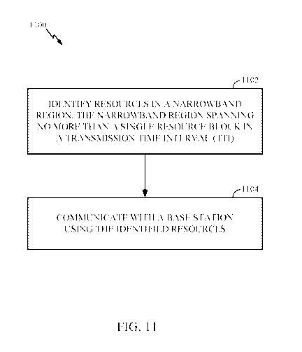
[0080] FIG. 11
illustrates example operations 1100 for LIE compatible very narrow
band design, in accordance with aspects of the present disclosure. The
operations 1100
may be performed, for example, by a UE.
[0081] The
operations 1100 begin, at 1102, where the UE identifies resources in a
narrowband region, the narrowband region spanning no more than a single
resource
block in a transmission time interval (TTI). At 1104, the UE communicates with
a base
station using the identified resources.
CA 02985239 2017-11-06
WO 2016/205449
PCT/US2016/037756
[0082] FIG. 12 illustrates example operations 1200 for LTE compatible
very narrow
band design, in accordance with aspects of the present disclosure. The
operations 1200
may be peiformed, for example, by a base station (BS). The operations 1200
begin, at
1202, where the BS identifies resources in a narrowband region, the narrowband
region
spanning no more than a single resource block in a transmission time interval
(TTI). At
1204, the BS communicates with at least one UE using the identified resources.
100831 The various operations of methods described above may be performed
by
any suitable means capable of perfonning the corresponding functions. The
means
(e.g., means for identifying, means for communicating, etc.) may include
various
hardware and/or software component(s) and/or module(s) (e.g., in connection
with UE
650 and eNB 610 of FIG. 6), including, but not limited to a circuit,
transceiver, antenna,
an application specific integrated circuit (ASIC), or processor. Generally,
where there
are operations illustrated in the Figures, those operations may be performed
by any
suitable corresponding counterpart means plus function components.
[0084] It is understood that the specific order or hierarchy of steps in
the processes
disclosed is an example of exemplary approaches. Based upon design
preferences, it is
understood that the specific order or hierarchy of steps in the processes may
be
rearranged while remaining within the scope of the present disclosure. The
accompanying method claims present elements of the various steps in a sample
order,
and are not meant to be limited to the specific order or hierarchy presented.
[0085] Those of skill in the art would understand that information and
signals may
be represented using any of a variety of different technologies and
techniques. For
example, data, instructions, commands, information, signals, bits, symbols,
and chips
that may be referenced throughout the above description may be represented by
voltages, currents, electromagnetic waves, magnetic fields or particles,
optical fields or
particles, or combinations thereof.
[0086] Those of skill would further appreciate that the various
illustrative logical
blocks, modules, circuits, and algorithm steps described in connection with
the
disclosure herein may be implemented as hardware, software, or combinations
thereof.
To clearly illustrate this interchangeability of hardware and software,
various illustrative
components, blocks, modules, circuits, and steps have been described above
generally in
terms of their functionality. Whether such functionality is implemented as
hardware or
software depends upon the particular application and design constraints
imposed on the
overall system. Skilled artisans may implement the described functionality in
varying
21
CA 02985239 2017-11-06
WO 2016/205449
PCT/US2016/037756
ways for each particular application, but such implementation decisions should
not be
interpreted as causing a departure from the scope of the present disclosure.
100871 The various illustrative logical blocks, modules, and circuits
described in
connection with the disclosure herein may be implemented or performed with a
general-
purpose processor, a digital signal processor (DSP), an application specific
integrated
circuit (ASIC), a field programmable gate array (FPGA) or other programmable
logic
device (PLD), discrete gate or transistor logic, discrete hardware components,
or any
combination thereof designed to perform the functions described herein. A
general
purpose processor may be a microprocessor, but in the alternative, the
processor may be
any conventional processor, controller, microcontroller, or state machine. A
processor
may also be implemented as a combination of computing devices, e.g., a
combination of
a DSP and a microprocessor, a plurality of microprocessors, one or more
microprocessors in conjunction with a DSP core, or any other such
configuration.
100881 The steps of a method or algorithm described in connection with
the
disclosure herein may be embodied directly in hardware, in a software module
executed
by a processor, or in a combination thereof. A software module may reside in
RAM
memory, flash memory, PCM (phase change memory), ROM memory, EPROM
memory, EEPROM memory, registers, hard disk, a removable disk, a CD ROM, or
any
other form of storage medium known in the art. An exemplary storage medium is
coupled to the processor such that the processor can read information from,
and write
information to, the storage medium. In the alternative, the storage medium may
be
integral to the processor. The processor and the storage medium may reside in
an ASIC.
The ASIC may reside in a user terminal. In the alternative, the processor and
the
storage medium may reside as discrete components in a user terminal.
100891 In one or more exemplary designs, the functions described may be
implemented in hardware, software, or combinations thereof. If implemented in
software, the functions may be stored on or transmitted over as one or more
instructions
or code on a computer-readable medium. Computer-readable media include both
computer storage media and communication media including any medium that
facilitates transfer of a computer program from one place to another. A
storage medium
may be any available medium that can be accessed by a general purpose or
special
purpose computer. By way of example, and not limitation, such computer-
readable
media can comprise RAM, ROM, EEPROM, flash memory, PCM, CD-ROM or other
optical disk storage, magnetic disk storage or other magnetic storage devices,
or any
22
CA 02985239 2017-11-06
WO 2016/205449
PCT/US2016/037756
other medium that can be used to carry or store desired program code means in
the form
of instructions or data structures and that can be accessed by a general-
purpose or
special-purpose computer, or a general-purpose or special-purpose processor.
Also, any
connection is properly termed a computer-readable medium. For example, if the
software is transmitted from a website, server, or other remote source using a
coaxial
cable, fiber optic cable, twisted pair, digital subscriber line (DSL), or
wireless
technologies such as infrared, radio, and microwave, then the coaxial cable,
fiber optic
cable, twisted pair, DSL, or wireless technologies such as infrared, radio,
and
microwave are included in the definition of medium. Disk and disc, as used
herein,
includes compact disc (CD), laser disc, optical disc, digital versatile disc
(DVD), floppy
disk and Blu-ray disc where disks usually reproduce data magnetically, while
discs
reproduce data optically with lasers. Thus, in some aspects computer-readable
media
may comprise non-transitory computer-readable media (e.g., tangible media). In
addition, for other aspects computer-readable media may comprise transitory
computer-
readable media (e.g., a signal). Combinations of the above should also be
included
within the scope of computer-readable media.
100901 As used herein, a phrase referring to "at least one of' a list of
items refers to
any combination of those items, including single members. For example, "at
least one
of: a, h, or c" is intended to cover a, b, c, a-h, a-c, b-c, and a-h-c, as
well as any
combination with multiples of the same element (e.g., a-a, a-a-a, a-a-b, a-a-
c, a-b-b, a-
c-c, b-b, b-b-b, b-b-c, c-c, and c-c-c or any other ordering of a. b, and c).
The term "or"
is intended to mean an inclusive "or" rather than an exclusive "or." That is,
unless
specified otherwise, or clear from the context, the phrase "X employs A or B"
is
intended to mean any of the natural inclusive permutations. That is, the
phrase "X
employs A or B" is satisfied by any of the following instances: X employs A; X
employs B; or X employs both A and B. The articles "a" and "an" as used in
this
application and the appended claims should generally be construed to mean "one
or
more" unless specified otherwise or clear from the context to be directed to a
singular
fonn.
100911 The previous description of the disclosure is provided to enable
any person
skilled in the art to make or use the disclosure. Various modifications to the
disclosure
will be readily apparent to those skilled in the art, and the generic
principles defined
herein may be applied to other variations without departing from the spirit or
scope of
the disclosure. Thus, the disclosure is not intended to be limited to the
examples and
23
CA 02985239 2017-11-06
WO 2016/205449
PCT/US2016/037756
designs described herein but is to be accorded the widest scope consistent
with the
principles and novel features disclosed herein.
24