Note: Descriptions are shown in the official language in which they were submitted.
SUSPENDED LAYERED ENERGY ABSORBING MATERIAL FOR
VEHICLE ARRESTING SYSTEMS
CROSS REFERENCE TO RELATED APPLICATIONS
[0001] This application claims the benefit of U.S. Provisional Application
Serial
No. 62/163,180, filed May 18, 2015, titled "Composite Layered Energy Absorbing
Material for Vehicle Arresting Systems,".
FIELD OF THE DISCLOSURE
[0002] Embodiments of the present disclosure relate generally to
vehicle arresting
systems that are designed for installation at the end of a runway or other
surface that
is subject to potential vehicle overrun. Embodiments find particular use when
installed at the end of an aircraft runway and when used to arrest light
aircraft.
BACKGROUND
[0003] Vehicle arresting systems are used as barriers at the end of
runways to
decelerate aircraft that overrun the end of the runway. These systems are
designed to
predictably and reliably crush (or otherwise deform or displace) under the
pressure of
aircraft wheels. The materials used in such a system are generally
compressible,
deformable, crushable, or otherwise able to be compressed, deformed, or
crushed
upon appropriate impact. The materials are generally designed to have a low
strength
that allows their crushing upon impact. During an arrestment, the wheels of
the
aircraft crush (or deform) the material. The depth of wheel penetration into
the
material is dependent on the vertical load applied by the material. The
deceleration of
the aircraft is dependent on the drag load applied by the material. In most
arresting
systems, the main core crushable material has isotropic properties which
provide a
fixed ratio between the wheel penetration and deceleration for each aircraft.
[0004] Due to this ratio, traditional arresting systems may not be able
to
decelerate certain lighter aircraft in the desired or available overrun area.
For
example, light aircraft may not have enough weight upon impact with the
vehicle
arresting barrier to cause the wheels of the aircraft to sink deep enough into
the barrier
material or otherwise crush enough of the barrier for arrestment.
1
CA 2985374 2020-02-04
CA 02985374 2017-11-07
WO 2016/187276
PCT/US2016/033037
BRIEF SUMMARY
[0005] Embodiments
of the invention described herein thus provide systems and
methods for arresting aircraft. In specific embodiments, the systems and
methods can
be useful in arresting light aircraft because they typically do not have the
weight to
penetrate available EMAS systems. However, it should be understood that the
discloses systems and methods may work for any type of aircraft or vehicle,
including
commercial aircraft. The system is
generally provided as a structure having a
suspended layer of energy absorbing material. A lower portion of the system
can
have a lower strength/is weaker, which can be used as a method to suspend an
upper,
stronger/more highly energy absorbent portion of the system. This results in
less
vertical resistance to penetration while still providing a large(er) force in
the
horizontal plane (drag load).
[0006] In one
example, there is provided a vehicle arresting system layered
structure that has at least one suspended upper portion of energy absorbing
material
having a first strength, and a lower base portion comprising a material of a
second,
lower strength than the material of a first strength. The lower base portion
can be a
layer of a more easily crushable material than the upper suspended portion. In
some
examples, the suspended upper portion comprises deformable material. In other
examples, the suspended upper portion comprises crushable material.
[0007] There may be
provided additional portions of material that decrease in
energy absorbing capabilities moving from the upper portion to the lower
portion.
The suspended upper portion and the lower base portion comprise gradients
within the
structure. Furtheimore, the gradients can extend between the suspended upper
portion
and the lower base portion and further extend between a foremost portion and a
rearmost portion.
[0008] In other
examples, the lower base portion includes one or more columns of
the material of a lower strength with one more voids therebetween. The
material of a
lower strength of the lower base portion can comprise one or more voids.
[0009] In use, there
is provided a method for arresting an aircraft, comprising,
installing a vehicle arresting system having any of the above features at an
end of a
2
CA 02985374 2017-11-07
WO 2016/187276
PCT/US2016/033037
runway or other overrun area. Specific examples may be installed at an airport
or on
a runway that is accessed by lightweight aircraft.
BRIEF DESCRIPTION OF THE DRAWINGS
[0010] FIG. 1 shows a schematic view of an aircraft wheel deforming a
layered
structure arresting system.
100111 FIG. 2 shows a schematic view of an aircraft wheel crushing a
layered
structure arresting system.
[0012] FIG. 3 shows a schematic illustrating layers of high to low
strength
materials.
[0013] FIG. 4 shows a schematic illustrating an alternate embodiment of
layers of
high to low strength materials.
[0014] FIG. 5 shows a schematic of a structure having a gradient of
strength
therethrough.
[0015] FIG. 6 shows a schematic of a structure having further gradients
of
material strengths.
[0016] FIG. 7 shows a schematic illustrating an upper layer of high-
strength
material and lower layer made of a combination of low strength material and
voids.
[0017] FIG. 8 shows a schematic illustrating a lower portion material
having
voids therein.
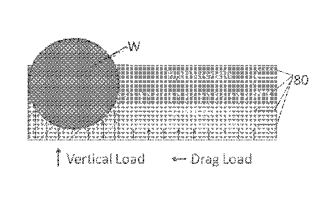
[0018] FIG. 9A shows a schematic of an example of a typical EMAS high-
strength material.
[0019] FIG. 9B shows a schematic of a layered structure and loads applied
in use.
DETAILED DESCRIPTION
[0020] Embodiments of the present invention provide a suspended layer of
energy absorbing material used for vehicle arresting systems. The composite
material
is particularly designed for arresting light aircraft in an overrun event. As
used
herein, "light aircraft" generally means aircraft that are lighter than
traditional wide-
3
CA 02985374 2017-11-07
WO 2016/187276
PCT/US2016/033037
body or twin-aisle aircraft used for long haul flights. The term "light
aircraft"
includes but is not limited to business jets, microjets, cessnas, regional
airliners,
commuter aircraft, short-haul aircraft, or civil aviation aircraft. Light
aircraft are
generally lighter than traditional commercial passenger aircraft.
[0021] In a overrun situation, the wheels of an aircraft may not have a
load that
can penetrate a traditional arresting system in the vertical load direction in
the way
that the heavy load of a larger aircraft would. Wheels of light aircraft may
not sink
deep enough in a traditional vehicle arresting barrier system. Additionally,
effective
arresting of an overrun light aircraft may benefit from a shallow arresting
system,
which can help avoid propeller strikes.
[0022] Accordingly, the suspended layer of energy absorbent material
described
herein is designed to provide additional drag load in the horizontal
direction. The
general intent is to accommodate/apply- a larger horizontal component of force
in the
arresting process, while eliminating some of the required vertical load
required for
crushing of the barrier material. The result is that wheels of a light
aircraft are
allowed to sink deeper into the lower layer of the arresting system, but an
appropriate
drag load is still provided by the upper layer.
[0023] The inventors have thus provided an arresting system that has the
ability to
vary the drag and vertical load of the system. This can allow for better
arresting in a
shorter overrun distance. This can also allow for using the same area to
arrest
vehicles overrunning the runway at higher speeds (e.g., current engineered
materials
arresting systems (EMAS) are designed for exit speeds up to 70 knots).
[0024] The improved system 10 is generally provided with a suspended
layer,
resulting in more than one layer of varied material strength. A lower base
portion of
the system generally has a lower strength/is weaker than an upper portion of
the
system. By providing a lower strength material at the lower portion of the
system,
there is less vertical resistance to penetration. The practical effect of this
design is that
vehicle wheels, upon penetration of the upper/stronger portion,
penetrate/crush/can be
stopped by the drag load applied by the upper portion. A schematic of this
effect is
.. provided by Figure 9B, described in more detail below. As shown in this and
other
figures, because of the low strength lower portion, the amount of wheel
penetration is
4
CA 02985374 2017-11-07
WO 2016/187276
PCT/US2016/033037
such that application of the drag load from the upper layer (illustrated by
horizontal
arrows 80) can be in line with the aircraft axle. Only the upper layer(s)
apply/applies
the drag load in line with the aircraft axel. The lower base layer is simply
present in
order to suspend the upper layer; it is not intended to add any strength/drag
load to the
system.
[0025] Other EMAS systems that have experimented with different strengths
of
materials have provided the denser/stronger material at the bottom and a
lighter/weaker material as the upper/top layer. The general theory behind such
systems is that they must be capable of stopping large, heavy aircraft and
need to have
the majority of the system made of the high-strength material. However, the
wheels of
light aircraft do not always penetrate deep enough into the denser/stronger
material at
the bottom. The present inventors thus sought to provide a system that is
capable of
stopping light aircraft of lower weight up to large commercial aircraft within
a shorter
EMAS bed. The prior art systems of providing lighter material on top have only
allowed lightweight aircraft to penetrate the top layer, but not penetrate
deeply
enough into the high-strength lower layer. The system described herein, with a
lower
layer suspending an upper layer of higher strength/higher energy absorbent
characteristics, allows for the wheel of an aircraft to penetrate the EMAS
system with
the vertical load typically required by a lower strength material but still
providing the
drag load of a higher strength material.
[0026] In general, the vehicle arresting systems described herein provide
at least
one suspended upper portion/laver of a compressible material that is supported
by a
lower base portion or area. The lower base layer or portion of material
generally has
lower energy absorption characteristics than the suspended layer. In other
words, the
suspended layer is a more highly energy absorbent material that is suspended
by a
lower material of a lesser or lower energy absorption capability than the
layer directly
above or vertically adjacent thereto. The vehicle arresting system may be an
elevated
panel or plane of compressible material, with the compressible material having
a
plurality of layers with energy absorption capabilities that decrease relative
to the
panel or layer directly above said panel (when moving down the vertical axis
from the
upper to lower most layer).
5
CA 02985374 2017-11-07
WO 2016/187276
PCT/US2016/033037
[0027] In one example, the system 10 provides two or more horizontal
layers 12,
14 of crushable (or deformable) material. The upper suspended layer 12 is
designed
as having a higher strength than the lower base layer 14. The layers may be
horizontal panels of crushable (or deformable) material(s). Multiple layers
are
illustrated by figures 1-4. In other examples, the system 10 may provide a
gradient 16
of strengths formed within a single structure 18 of material. The structure 18
may be
a block, a gradient system, or any other appropriate compilation of material.
Various
types of gradients are possible within the material, as described in more
detail below.
Gradients are illustrated by figures 5-6. In another example, the system 10
may
provide a higher strength upper suspended layer 12 with support columns 20
forming
the lower base layer, having voids 22 positioned therebetween. An example of
this
embodiment is shown by FIG. 7. In a further example, a lower portion 24 of the
material may be provided with varying sized voids 26, rendering the material
at the
lower portion 24 weaker than the material at the upper portion 28. An example
of this
is illustrated by Figure 8. All of these options are described in more detail
below.
Any of the materials described herein may be used for any of the layers,
gradients, or
portions. The layers, gradient, or portions of the material may all be
referred to as a
-layered structure," even if distinct and separate layers are not specifically
provided.
[0028] Each of these layers, gradients, or portions of the layered
structure material
is designed for the arresting performance of the system, but they may provide
protection in addition to arresting performance. For example, a stronger more
dense
upper layer may permit vehicles/personnel to traverse the EMAS system, whereas
if
the system was made of only of the lower strength material, such travel would
not be
possible.
[0029] Examples of materials that may be used for any of the layers,
portions, or
gradients described herein include but are not limited to cellular cement,
cellular
cementitious material, polymeric foam, honeycomb, metal honeycomb, macro
particles, vermiculite, perlite, ceramics, foam glass and other isotropic or
anisotropic
crushable/deformable materials, or combinations thereof Each material can have
different mechanical and physical properties and geometry. Each material can
be
selected to tune the desired properties of the overall structure.
6
CA 02985374 2017-11-07
WO 2016/187276
PCT/US2016/033037
[0030] One specific example of materials forming the layered structures
may be a
combination of a polymeric foam forming the lower layer and a metallic
honeycomb
forming the upper layer. The polymeric foam may have its density/strength
varied
based on foam formation methods. In another specific example, a low strength
honeycomb layer may support a layer of cellular cement or polymeric foam. In a
further example, a low strength/density polymeric foam may be used to support
an
upper layer of cellular cement. Other combinations of materials and strengths
are
possible and considered within the scope of this disclosure.
[0031] The materials may be selected to provide the desired strength
ratios. In one
example, a drag to vertical load ratio may reach 1:1. It may be possible to
get the
ratio even higher than 1:1, and higher drag to vertical loads are desirable.
For
example, the ratio may be 2:1, 5:1, or 10:1. The general goal is that for
every pound
of drag, there be a equal or smaller amount of vertical load required to
penetrate into
the system. It is desirable that the resistance of the aircraft wheel required
to travel
through the high strength material in the vertical direction be minimized, and
that
horizontal resistance (drag) being applied to the wheel be great.
[0032] The layered structure may be comprised of different materials. For
example, Figures 1 and 2 show a lower layer 14 of weaker material positioned
under
an upper layer 12 of a higher strength material. The material itself may be
the same
material with different physical/mechanical properties. Alternatively,
different types
of material may be provided to form each layer 12, 14. In Figure 1, the upper
layer 12
is a deformable, strong material. The lower layer 14 is weaker, crushable
material. In
this example, the lower portion is thicker (or otherwise forms more of the
bulk of the
system) than the upper portion.
[0033] The system (both upper and lower layers) may be coated in a coating,
film
or shell, collectively referred to as a "shell." This shell can be provided to
protect the
core energy absorbing material from the effects of weathering/jet. blast. The
shell may
be designed to shear and/or tear, allowing the wheel to penetrate into the
core
material. The shell may be elastic in nature, allowing it to deform and
elongate (but
not tear or shear) such that it deforms enough to allow the wheel to
crush/deform the
core material. The core can be crushed and pressed and moved upon pressure,
and the
shell can elongate and deform to allow the wheel to move through the material,
while
7
CA 02985374 2017-11-07
WO 2016/187276
PCT/US2016/033037
containing the upper and lower layers, and preventing them from fracturing
into
pieces. In another example, the upper layer 12 may function like an elastic
coating.
For example, it may be an elastic sprayable polymer. The upper layer 12 can
deform
upon touch but does not lose its integrity. The lower layer 14, however, can
be
caused to crush or otherwise deform beneath the upper layer 12. In use, the
wheel
"W" penetrates the lower layer 14 without actually contacting the lower layer
directly.
The coating 12 in this example functions to contain the core of the
lower/upper layers
14.
[0034] In Figure 2, the upper layer 12 is a laver of a strong, crushable
material
and the lower layer 14 is a layer of a weaker, crushable material. These
materials may
be the same materials, modified separately as described below in order to
alter their
respective strengths. Alternatively, these materials may be completely
different
materials having different strengths that are layered upon one another. As
illustrated,
the aircraft wheels W are allowed to crush both layers 12, 14 during contact
and the
arrestment process.
[0035] For example, if the material used is polymeric foam, it is
possible to alter
the density/strength of the foam. This may done by varying cell alignment for
different portions of the structure. In another example, this may be done by
injecting
voids into the foam in the form of air bubbles in order to weaken the lower
portion
areas of the foam.
[0036] Additionally or alternatively, one or more chunks of lighter
material may
be mixed into the foam or other material that forms the lower portion of the
system.
Additionally or alternatively, particle sizes of various materials used may be
varied to
change densities of the players/portions.
[0037] Figure 3 illustrates a structure comprised of multiple layers, each
with
differing energy absorption characteristics. Each layer, plane or zone has a
specified
strength that generally differs from one or more layers, planes or zones
thereabove.
The upper most layer 50 has the highest strength, with the layers therebelow
decreasing in strength. For example, the next layer 52 has a high strength (as
compared to layer 50). The next layer 54 has a medium strength (again,
comparatively). The next layer, the lowermost layer 56, has a comparatively
low
8
CA 02985374 2017-11-07
WO 2016/187276
PCT/US2016/033037
strength. Although an example with four layers is shown, it should be
understood that
more or fewer layers may be provided. It is also possible that the layer
strengths need
not vary greatly or substantially with respect one another. Small strength
steps are
possible and considered within the scope of this disclosure.
[0038] Additionally, an alternate example may be a high/low/high/low
embodiment. In this example, the upper most layer may have a high strength,
the next
layer may have a low strength, the next layer down may have a high strength,
and the
lowermost layer may have a low strength. The general concept is providing
alternating of layer strengths.
[0039] In any of the layer examples, it is possible for the layers to be
bonded or
adhered to one another using any appropriate EMAS technique. Adhesive or high
friction are examples only. In another example, it is possible for the layers
to be
stepped or laid on top of one another. In any option, the layers may then be
contained
by a separate containment system. Exemplary containment systems are shown and
described by many of the present assignee's pending applications and issued
patents.
Alternatively, the containment system could be a sprayable covering, a flame-
resistant
coating, a weather-resistant coating or any other appropriate outer layer.
These
securement,'containment system options may be used in any of the examples
described herein.
[0040] Figure 4 illustrates an alternate embodiment in which the specified
strength layers have varying heights. In the example shown, the uppermost,
highest
strength layer 50 is shown as thicker than the lower layers. Alternatively, it
is
possible for the uppermost, highest strength layer 50 to be thinner than the
lower
layers, such that the high, medium, and/or low strength materials provide a
larger
portion of the barrier material.
[0041] Figure 5 illustrates a gradient material 16 formed as a structure
18. As
discussed above, the structure may be a block, a gradient system, or any other
appropriate compilation of materials. Rather than having two or more separate
layers
bonded, this embodiment provides a single structure 18 that has an increasing
density
moving upwards from the bottom towards the top face 40 of the structure or
block,
and the direction of arrow 70. Considered a different way, there is a
decreasing
9
CA 02985374 2017-11-07
WO 2016/187276
PCT/US2016/033037
density moving down through the structure or block, from the top towards the
bottom
face 42. The gradient of energy absorbing ability decreases from the upper
most
plane to the lower most plane. This gradient of energy absorbing ability may
be
provided by any of the above-described modifications to a material. It may be
referred to as a top-to-bottom gradient.
[0042] Figure 6 illustrates a gradient material 30 formed as a structure
18. As
discussed above, the structure may be a block, a gradient system, or any other
appropriate compilation of materials. In this example. sections of material
are
oriented to have a gradient of energy absorbing capabilities that increases
from lower
most to uppermost, as well as from foremost to rear most of the system. More
specifically, a lower strength material is provided at a front portion 32 of
the structure.
A higher strength material is provided at a rear portion 34 of the structure.
The
material therebetween 36 is generally formed as a gradient of gradually
increasing
strength. The gradually increasing strength of this section moves from a lower
portion of the structure to an upper portion of the structure, as well as from
a front
portion to a rear portion. This example provides an energy absorbent material
with
the internal energy absorbing characteristics varying from the lowest point to
the
uppermost point and varying from the frontmost point to the rearmost point.
[0043] Although shown as a gradient, it is also possible to provide this
effect
using various structures, blocks, or layers. For example, the frontmost
portion,
structure or block may be provided having a lower energy absorption ability
(i.e., a
weaker strength) and rear most and higher portions, structures, or blocks may
be
provided having a higher energy absorption ability (i.e., a stronger
strength).
[0044] Figure 7 illustrates an embodiment having an upper layer 12 of a
high
strength and a lower portion 60 that is formed of support columns 20 of low
strength
material with voids 22 interspersed therebetween. The voids 22 may be actual
openings in which no material is present. In other examples, the voids 22 may
be
formed of material having an even lower strength than the low strength support
columns 20. The result is that a highly energy absorbent material forms the
uppermost layer and is supported by columns of lower energy absorbent material
with
voids between the columns.
CA 02985374 2017-11-07
WO 2016/187276
PCT/US2016/033037
[0045] Figure 8 illustrates a schematic of a configuration in which the
lower
portion 24 is made to have lower energy absorption abilities through the
introduction
of voids 26. The voids 26 are illustrated as having varying sizes and shapes.
It should
be understood however that the voids may all be similarly sized and shaped.
The
voids may be formed using any of the above-described methods or materials.
Additionally, although the voids are shown as circular, it should be
understood that
the shapes would greatly vary depending upon the way that the voids are
formed. The
general effect of voids 26 is that the lower portion 24 of the material has a
lower
energy absorption capability.
[0046] This perfomiance of the systems described herein is different than
traditional EMAS systems, which have isotropic material and system properties.
A
traditional EMAS system is illustrated by FIG. 9A. This example is entirely a
single
strength material. By contrast, the suspended layer structures disclosed can
be
designed to have a higher ratio of drag load to vertical load. This is
illustrated by
FIG. 9B. Once the aircraft wheel W has penetrated into the system by
deformation,
crushing or by other method, the upper layer(s) would provide higher drag load
than a
typical EMAS system with similar wheel penetration, leading to a more rapid
deceleration of the aircraft during an arrestment. One purpose of this system
is to be
able to provide the drag load of a high strength material, but only require
the vertical
load of a low strength material to penetrate into it. One benefit provided
(vs. a
typical EMAS) is that given the same vertical load, the aircraft will be able
to
penetrate deeper into a suspended layer structure due to the low strength
lower layer,
but receive the same amount of drag load as if the wheel had penetrated (the
same
depth) into the higher strength material.
[0047] Once the wheel has penetrated into the system by deformation,
crushing,
or by other method, the upper layer(s) provide a higher drag load than a
typical
EMAS system would for a similar weight aircraft, leading to a more rapid
deceleration of the aircraft during an arrestment
[0048] Some light aircraft have propellers or generally have limited
ground
clearance below, such that their wheels cannot penetrate certain depths.
Accordingly,
the structures described herein may be designed having upper and lower layers
of
various heights, depending upon needs of the particular runway or aircraft to
be
11
CA 02985374 2017-11-07
WO 2016/187276
PCT/US2016/033037
stopped. One non-limiting example includes 5 to 12 inches of the material
forming
the barrier, In one specific example, a 7 inch barrier may work with certain
aircraft.
The barriers described herein may include a ramp up portion, they may be
installed
directly above ground, and/or they may be installed slightly or greatly below
ground.
[0049] The varying strength layers allow the aircraft wheels W to penetrate
into
the system with the force required by a low strength material, but to
encounter the
drag load that would typically be produced by a higher strength material. The
layer
structure may be arranged in height and positioning and strength/energy
absorption
based upon the desired degree of penetration and resulting drag load for a
specific
size/weight of a specific fleet mix. The drag and vertical loads can be tuned
or
modified to allow for better arresting in a shorter overrun distance and/or to
allow for
the same area to arrest vehicles overrunning the runway at higher speeds. Each
layer
can have different mechanical/physical properties and geometry and will be
selected
to tune to the desired properties of the overall structure.
[0050] Changes and modifications, additions and deletions may be made to
the
structures and methods recited above and shown in the drawings without
departing
from the scope or spirit of the disclosure or the following claims.
12