Note: Descriptions are shown in the official language in which they were submitted.
ELECTRICAL EQUIPMENT WITH ADDITIONAL COMPARTMENT AND WIRING TO ACCOUNT
FOR TEMPERATURE LIMITATIONS OF CONNECTED CONDUCTORS
TECHNICAL FIELD
[0001] This document relates to electrical equipment with an additional
compartment and wiring to
account for temperature limitations of connected electrical equipment
conductors, and in some cases this
document relates to electrical distribution panels.
BACKGROUND
[0002] Electrical distribution panels are being modified for use with
current transformers for
metering purposes; however, such an installation may be a breach of the local
building code, such as in
Alberta, Canada. The Canadian Electrical Code does not allow the splicing of
wires in a breaker compartment
or the use of the distribution panel as a wire way, trough or tap point.
Existing panels use a breaker
temperature rating of 60/75 degrees Celsius for copper and or aluminum
connected wires, which is typically
about two thirds the temperature capacity of the installed conductor, thus
creating inefficiencies in circuit
design and capabilities. The relatively lower temperature rating of the
breaker also increases the cost of
connecting conductors that supply circuits as such are typically required to
have an increased overall diameter
to account for the lower temperature rating connection at the breaker
terminal.
SUMMARY
[0003] A pre-fabricated electrical apparatus comprising: a main housing
configured to enclose
electrical equipment in use; a splice compartment mounted, or integrally
formed, external to and adjacent the
main housing; a conductor passage defined between the main housing and the
splice compartment; and in
which the main housing and splice compartment are configured to, in use,
permit a conductor to extend from
a first conductor termination point, defined within the main housing, to a
second conductor termination point,
defined within the splice compartment, with the second termination point
having a temperature rating that is
higher than a temperature rating of the electrical equipment.
[0004] A method is also disclosed comprising: prefabricating, at a
prefabrication facility, an
electrical apparatus by mounting or integrally forming a splice compartment
adjacent an external part of a
main housing; and installing the electrical apparatus at an end user facility,
which is remote from the
prefabrication facility.
[0005] A distribution panel is also provided including a first compartment
containing a breaker, and
a second compartment separated from the first compartment.
[0006] In various embodiments, there may be included any one or more of the
following features: A
connector lug electrically connected to the conductor at the second
termination point. A conductor that
extends between and defines both the first termination point and the second
termination point. An external
CA 2986409 2017-11-22
circuit conductor extends from outside both the splice compartment and main
housing, and into electrical
contact with the second termination point, the external circuit conductor
having a temperature rating that is
higher than the temperature rating of the electrical equipment in use. .A
cross-sectional diameter of the
external circuit conductor is smaller than a cross-sectional diameter of the
conductor. The splice compartment
comprises a plurality of conductors that define respective first termination
points and second termination
points. The external circuit conductor comprises a plurality of respective
external circuit conductors, each
electrically connected between a respective conductor, of the plurality of
conductors, and each forming part
of a respective independent external circuit of a plurality of independent
external circuits. Electrical
equipment enclosed by the main housing, in which at least some of the
plurality of conductors are pre-wired
out-of-electrical contact with the electrical equipment. The external circuit
conductor comprises an aluminum
conductor, and in some cases the conductor comprises a non-aluminum conductor.
The conductor and / or
external circuit conductor comprises a copper conductor. The conductor has a
length of 1.2 meters or greater.
The conductor has a length of 1.2 to 1.8 meters. Electrical equipment enclosed
by the main housing. The
electrical equipment carries out one or more of the following electrical
functions: distribution, switching,
voltage modifying, current modifying, energy conversion, energy generation,
light generation, or overcurrent
protection. The electrical equipment comprises a distribution panel. The
conductor forms part of a branch
circuit, which includes a branch circuit breaker located within the main
housing. A main overcurrent
protection device connected one or both of upstream of the distribution panel
or within the distribution panel,
in which the second termination point has a temperature rating that is higher
than a temperature rating of the
main overcurrent protection device. The splice compartment comprises a
plurality of splice compartments
each containing respective conductors. The plurality of splice compartments
comprise a primary splice
compartment and a secondary splice compartment. The primary splice compartment
is configured to supply
electricity to the electrical equipment in use, and the secondary compartment
is configured to receive
electricity from the electrical equipment in use. The second termination point
of the conductor of the primary
splice compartment has a temperature rating that is higher than the
temperature rating of the electrical
equipment. Electrical equipment enclosed by the main housing, in which the
electrical equipment comprises
one or more of switchgear, a transformer, a motor control panel, a motor, a
motor starter, a generator, a light
fixture, a fused disconnect switch, an unfused disconnect switch, a power
monitor, and a motor disconnect
switch. The electrical equipment is rated to carry a maximum voltage of up to
and including 600 V, although
higher or lower voltages may be used. The splice compartment comprises a power
metering device. The
conductor passage is defined by a raceway that connects the main housing and
splice compartment. Enclosing
electrical equipment within the main housing. Extending a conductor between a
first termination point,
within the main housing, and a second termination point within the splice
compartment, with the second
termination point having a temperature rating that is higher than a
temperature rating of the electrical
2
CA 2986409 2017-11-22
equipment. The enclosing and extending stages are carried out during the
prefabricating stage at the
prefabrication facility. After installing, the electrical equipment carries
out one or more of the following
electrical functions: distribution, switching, voltage modifying, current
modifying, energy conversion, energy
generation, light generation, or overcurrent protection. The prefabrication
facility is at least five kilometers
away from the end user facility. The second compartment contains a terminal
connection point having a
higher than breaker temperature rating for branch circuit wires. The second
compartment contains a current
transformer configured to meter power. The second compartment contains a
termination point configured to
be part of an aluminum or copper conductor connection. The second compartment
contains a wire way. The
second compartment contains a wire splice connection point.
[0007] These and other aspects of the device and method are set out in the
claims, which are
incorporated here by reference.
BRIEF DESCRIPTION OF THE FIGURES
[0008] Embodiments will now be described with reference to the figures, in
which like reference
characters denote like elements, by way of example, and in which:
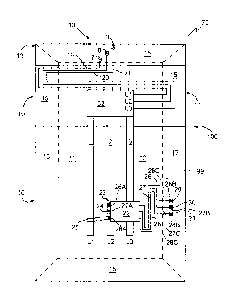
[0009] Fig. 1 is a front elevation schematic view of a distribution panel
with primary and secondary
splice compartments.
[0010] Fig. 2 is a right side elevation view of the distribution panel of
Fig. I.
[0011] Fig. 3 is a front elevation schematic view of a breaker connection
with primary and
secondary lug kits and an example of how such terminate within the secondary
compartment.
[0012] Fig. 4 is a partial front elevation schematic view of an embodiment
of a distribution panel
with primary and secondary splice compartments.
[0013] Fig. 4A is a left side elevation view of the distribution panel of
Fig. 4.
[0014] Fig. 5 is a side elevation schematic view of a fused disconnect
switch with primary and
secondary splice compartments.
[0015] Fig. 6 is a side elevation schematic view of a transformer with
primary and secondary splice
compartments connected to the main housing via raceways.
[0016] Fig. 7 is a side elevation schematic view of a motor with a splice
compartment connected to
the main housing.
DETAILED DESCRIPTION
[0017] Immaterial modifications may be made to the embodiments described
here without departing
from what is covered by the claims.
[0018] Ampacity is a portmanteau for ampere capacity defined by National
Electrical Safety Codes,
in some North American countries. Ampacity is defined as the maximum amount of
electric current a
3
CA 2986409 2017-11-22
conductor or device can carry before sustaining immediate or progressive
deterioration. Also described as
current rating or current-carrying capacity, ampacity is the RMS electric
current which a device or conductor
can continuously carry while remaining within its temperature rating.
[0019] The ampacity of a conductor depends on:
a. its insulation temperature rating;
b. the electrical resistance of the conductor material;
c. frequency of the current, in the case of alternating current;
d. ability to dissipate heat, which depends on conductor geometry and its
surroundings; and
e. ambient temperature.
[0020] All common electrical conductors have some resistance to the flow of
electricity. Electric
current flowing through such conductors may cause voltage drop and power
dissipation, which heats
conductors. Copper or aluminum can conduct a large amount of current without
damage, but long before
conductor damage, insulation would, typically, be damaged by the resultant
heat.
[0021] The ampacity for a conductor is based on physical and electrical
properties of the material
and construction of the conductor and of its insulation, ambient temperature,
and environmental conditions
adjacent to the conductor. Having a large overall surface area can dissipate
heat well if the environment can
absorb the heat.
[0022] The allowed current in a conductor generally needs to be decreased
(derated) when
conductors are in a grouping or cable, enclosed in conduit, or an enclosure
restricting heat dissipation. e.g.
The United States National Electric Code, Table 310.15(B)(16), specifies that
up to three 8 AWG copper
wires having a common insulating material (THWN) in a raceway, cable, or
direct burial has an ampacity of
50 A when the ambient air is 30 C, the conductor surface temperature allowed
to be 75 C. A single insulated
conductor in free air has 70 A rating.
[0023] Ampacity rating normally applies for continuous current, permitting
short periods of
overcurrent to occur without harm in most cabling systems. The acceptable
magnitude and duration of
overcurrent is a more complex topic than ampacity.
[0024] When designing an electrical system, one will normally need to know
the current rating for
the following:
a. Wires (conductors)
b. Printed Circuit Board traces, where included
c. Fuses
d. Circuit breakers; and
e. All or nearly all components used
4
CA 2986409 2017-11-22
[0025] Every electrical circuit, and every portion of an electrical
circuit, has an inherent temperature
rating, above which some event will happen, such as the tripping of an
adjacent overcurrent protection
device, or the degradation of the conductor or conductor insulation leading to
conductor failure. In some
cases the temperature rating is determined by the overcurrent protection
device within the environment, for
example within a distribution panel, as the overcurrent protection device will
be engaged to shut off currents
that cause local temperatures above the temperature rating of the overcurrent
protection device. An
overcurrent protective device is a device capable of providing protection for
service, feeder, and branch
circuits and equipment over the full range of overcurrent between its rated
current and its interrupting rating,
and including a fuse and a circuit breaker.
[0026] The groundwork for a better understanding of temperature rating
begins with a preliminary
discussion of several relevant subjects that include: conductor ampacity and
ambient temperature correction
factors, adjustment factors wherever more than three current-carrying
conductors are used, and conductor
overcurrent protection. Proper sizing of conductors and overcurrent protection
depends upon the application
of the requirements outlined in all of these sections, see Table I below as an
example.
[0027] Table 1: Allowable ampacities for not more than three
copper conductors, rated not more
than 5000V and unshielded, in raceway or cable (based on ambient temperature
of 30 degrees Celsius)
_____________ .. ________________________________________
Allowable ampacity ..
Size, 110C 125C 200 C
AWG or kuoil 60 C 75 C 90 C
14 15 20 25 25 30 35
12 20 25 30 30 35 40
30 35 40 45 45 60
a 40 50 55 65 65 80
6 55 65 75 go 90 110
4 70 85 95 105 115 140
3 85 100 115 125 135 165
2 95 115 130 145 155 190
1 110 130 145 165 175 215
0 125 150 i7, 190 200 245
00 145 175 195 220 235 290
000 165 200 225 255 270 330
0000 195 230 260 290 310 380
250 215 255 290 320 345 ¨
300 240 285 320 36(1 385 ¨
350 260 310 350 390 420 ¨
400 280 335 380 425 450 ¨
500 320 380 430 480 510 ¨
600 350 420 475 530 565 ¨
700 385 460 520 580 620 ¨
COL 1 Col. 2 Col. 3 C,ol. 4 Col. 5 Col, 6 Col.
7
_________________________________________ ¨
5
CA 2986409 2017-11-22
[0028] The temperature rating associated with a conductor's ampacity must
be selected and
coordinated so that the lowest temperature rating of any connected
termination, conductor, or device is not
exceeded. Conductor temperature limitations can be compared to the strength of
a chain. A chain is only as
strong as its weakest link.
[0029] For conductors, every termination (or connection) point is a
potential weak link. The fact that
a conductor's insulation has a 90 degrees C temperature rating does not mean
that the ampacity is
automatically selected from the 90 degrees C column. The lowest temperature
rating of the termination
points, along the conductor's path, determines the maximum ampacity. A
terminal is the point at which a
conductor from an electrical component, device or network comes to an end and
provides a point of
connection to external circuits. A termination point may simply be the end of
a wire or it may be fitted with a
connector or fastener.
[0030] The termination point with the lowest temperature rating may be the
determining factor for
selecting the conductor's ampacity. If the temperature rating of a termination
point is unknown, the conductor
ampacity must usually be selected from the 60 degrees C column regardless of
the insulation type. Likewise,
if any connection point has a temperature rating of 60 degrees C, the
conductor's ampacity may need to be
selected from the 60 degrees C column. Generally, where a conductor has a 90
degrees C temperature rating,
and the lowest temperature rating of the termination points is 75 degrees C
(or 60/75 degrees C), the
conductor's ampacity must be selected from the 75 degrees C column. Different
codes, such as the NEC
(National Electrical Code - U.S.) and the CEC (Canadian Electrical Code), have
different specific rules,
however, such rules are generally based on the inherent properties of the
conductor and the environment of
the conductor.
[0031] Referring to Fig. 4, a pre-fabricated electrical apparatus 75 is
disclosed, comprising a main
body / main housing 10, and one or more splice compartment, such as
compartment 15. The main housing 10
may be configured to enclose electrical equipment in use, such as a
distribution panel 100. The splice
compartment 15 may be mounted, or integrally formed, external to and adjacent
the main housing 10. A
conductor passage, such as passage 26C may be defined between the main housing
10 and the splice
compartment 15.
[0032] Referring to Fig. 4, the apparatus 75 may comprise a conductor, such
as conductor 26, that
extends between and defines both a first termination point 26A within the main
housing 10 and a second
termination point 26B within the splice compartment 15. In the example shown,
three conductors 26, 27, and
28 are shown defining respective first termination points 26A, 27A, and 28A,
and second termination points
26B, 27B, and 28B. Conductors may be bare, covered, or insulated. Conductors
include wires, cables and
other shapes and strips of electrically conductive material intended to carry
voltage.
6
CA 2986409 2017-11-22
[0033] Referring to Figs. 1 and 4, the splice compartment may comprise a
plurality of splice
compartments, such as compartments 11, 12, 13, 14, and 15. In some cases more
than one compartment
contains respective conductors. Referring to Fig. 4, in some cases plural
conductors, such as conductors 26,
27, and 28, may be positioned within a single compartment such as compartment
15, with each of the
plurality of conductors defining respective first termination points and
second termination points.
[0034] Referring to Fig. 1, the plurality of splice compartments may
comprise a primary splice
compartment, such as compartments 11, 12, 13, and 14, and a secondary splice
compartment 15. The primary
splice compartment or compartments may be configured to, in use, supply
electricity, for example from a
supply or feeder line, to the electrical equipment such as panel 100, for
example via compartment 11 and
conductor lugs 7, 8,9 and conductors 19, 20, and 21 to bus bars 1,2, and 3,
respectively. Referring to Fig. 4,
the secondary compartment may be configured to receive electricity from the
electrical equipment in use to
supply to an external load, such as an external circuit (not shown).
[0035] Referring to Fig. 4, the second termination point, for example
points 26B, 27B, and 28B, of
the conductor, in this case conductors 26, 27, and 28, respectively, of the
secondary splice compartment 15
may have a temperature rating that is higher than a temperature rating of the
electrical equipment, in this case
panel 100. Referring to Fig.1, the second termination point, for example
points 16B, 1 7 B , and 18B, of the
conductor, in this case conductors 16, 17, and 18, respectively, of the
primary splice compartment 15 may
have a temperature rating that is higher than a temperature rating of the
electrical equipment, in this case
panel 100. Thus, the additional compartments 12 and 15 may house terminals for
connecting a higher
temperature rated cable to a relatively lower temperature rated piece of
electrical equipment, such as panel
100, than would be possible if an external conductor were connected directly
to the electrical equipment.
[0036] Referring to Fig. 1A, a method may comprise prefabricating, at a
prefabrication facility 98,
an electrical apparatus 75 by mounting or integrally forming a splice
compartment, such as compartments 11
and 15, adjacent an external part of a main housing 10. An external part is
understood to include a part that
defines an outer periphery of the main housing. Mounting the splice
compartment to or outside the outer
periphery of the main housing distances the splice compartment from the heat
generation that may occur
within the main housing, for example caused by operation of an internal
breaker, and that may otherwise
contribute to a relatively low temperature rating for all conductors within
the main housing 10. The main
housing and/or splice compartments may include respective covers, for example
to provide respective
rainproof enclosures.
[0037] Referring to Fig. IA, the method may include installing the
electrical apparatus 75 at an end
user facility 96, which is remote from the prefabrication facility 98. In some
cases the prefabrication facility
98 is at least five, ten, fifteen, or more kilometers away from the end user
facility 96. The apparatus 75 may
be pre-fabricated and transported to a distribution and/or storage facility
(not shown), where the apparatus
7
CA 2986409 2017-11-22
may be sold and/or shipped out to the end user on demand. An example of an end
user facility 96 includes a
building or refinery, and installing includes permanent installation for the
purpose of running an electrical
system that incorporates the electrical equipment. At some point in the
method, for example during pre-
fabrication, electrical equipment may be enclosed within the main housing, and
a conductor may be extended
(pre-wired) between the main housing and the splice compartment. At least some
of the plurality of
conductors may be pre-wired out-of-electrical contact with the electrical
equipment, to provide an electrician
with the flexibility to decide whether or not to use the conductor if needed
during the installing stage.
[0038] The apparatus 75 may be pre-fabricated with one or more of the
electrical equipment and a
conductor 16 lacking. In some cases the main housing and splice compartment
are configured to, in use,
permit a conductor to extend from a first conductor termination point, defined
within the main housing, to a
second conductor termination point, defined within the splice compartment. In
some cases the main housing
may be configured to enclose electrical equipment in use. If the electrical
equipment and/or conductor is not
assembled with the apparatus 75 in the prefabricating stage, which may occur
in sub-stages across one, two,
or more facilities, then such may be added during an installation stage.
[0039] Electrical equipment may include any device or appliance that in
use runs a current within a
housing to perform a function at an end user facility 96. Appliances may carry
out the functions of clothes
washing, air-conditioning, food mixing, and deep frying for several examples.
In some cases, during use the
electrical equipment carries out one or more of the following electrical
functions: distribution, switching,
voltage modifying, current modifying, energy conversion, energy generation,
light generation, or overcurrent
protection. The electrical equipment may generate sufficient heat during use
such that within the main
housing and the electrical equipment, conductors are temperature rated to a
maximum of 75 degrees Celsius,
in some cases a maximum of 60 degrees Celsius.
[0040] In some cases electrical equipment may be provided with an
additional compartment which
could be internal or external separated from the main housing of the equipment
and the equipment
termination point. Provisions for wiring may be put in place from the
manufacturer or added at the time of
installation, and such conductors maybe based on the equipment temperature
rating typically 75 degrees
Celsius or less, in some cases 60 degrees Celsius. The internal conductors may
be wired from the termination
point of the equipment a minimum of 1.2 meters in length to the additional
compartment at the line and or
load conductor connection point, typical conductors used are rated at 90
degrees Celsius.
[0041] Referring to Fig. 3, an external circuit conductor, for example
conductors 91, 92, and 93,
may extend from outside both the splice compartment 15 and main housing 10,
and into electrical contact
with the second termination point, in this case points 26B, 27B,a and 28B,
respectively. The external circuit
conductor may have a temperature rating that is higher than the temperature
rating of the electrical
equipment, in this case panel 100, in use. As shown the external circuit
conductor may comprise a plurality of
8
CA 2986409 2017-11-22
respective external circuit conductors, each electrically connected between a
respective conductor, of the
plurality of conductors, and each forming part of a respective independent
external circuit of a plurality of
independent external circuits. In the example shown, the conductors 91, 92,
and 93 may extend to
independent respective external circuits. An independent circuit would be one
where one or more of
conductors 91, 92, and 93, are not associated with each other in any way, for
example if each conductor 91,
92, and 93 ran in different directions to different outlets. In other cases,
two or more of conductors 91, 92,
and 93 may be associated with each other on the same external circuit, for
example if one conductor formed a
positive lead, another conductor formed a negative lead, and the third a
neutral lead or ground.
[0042] Referring to Fig. 3, in some cases a cross-sectional diameter of the
external circuit conductor,
for example conductor 91, is smaller than a cross-sectional diameter of the
conductor, for example conductor
26. In most cases where a relatively higher temperature conductor, in this
case conductor 91, connects to a
relatively lower temperature ampacity rated conductor, in this case conductor
26, the load conductor 91
would be one size smaller. In some cases the size is more than one size
smaller, with sizes referring to wire
gauges, see Table 1 for examples of such. The use of a relatively thinner
diameter conductor 91 as an external
circuit conductor reduces the cost of materials required to complete the
external circuit, and hence reduces the
cost of the electrical work at the end user facility 96. In some cases, for a
ten panel installation a cost savings
of $35,000 or more may be realized by dropping one wire gauge from conductors
26 to conductors 91.
[0043] Referring to Fig. 4, in some cases the conductors, for example
conductors 26, 27, and 28,
may have a predetermined length selected to achieve the desired temperature
rating at the second termination
point. In some cases the conductor may have a length of 1.2 meters or greater,
for example 3.0 meters. In
some cases the conductor has a length of 1.2 to 1.8 meters. In some cases the
conductor may be oversized in
diameter to increase heat dissipation and reduce length.
[0044] Referring to Figs. 3 and 4, the electrical equipment may comprise a
distribution panel 100. A
distribution board (also known as panelboard, breaker panel, or electric
panel) is a component of an
electricity supply system that divides an electrical power feed into
subsidiary circuits, while typically
providing a protective fuse or circuit breaker for each circuit in a common
enclosure. Normally, a main
switch, and in recent boards, one or more residual-current devices (RCD) or
residual current breakers with
overcurrent protection (RCBO), are also incorporated. In a North American
distribution board, the circuit
breakers are generally positioned in two vertical columns. Circuit breaker
panelboards may be dead front, that
is, the operator of the circuit breakers is unable to contact live electrical
parts. During servicing of the
distribution board itself, though, when the cover has been removed and the
cables are visible, North
American breaker panelboards commonly have some live parts exposed. In some
cases a panel 100 includes a
panelboard - a single panel or group of panel units designed for assembly in
the form of a single panel,
including buses and automatic overcurrent devices, and equipped with or
without switches for the control of
9
CA 2986409 2017-11-22
light, heat, or power circuits, designed to be placed in a cabinet or cutout
box placed in or against a wall,
partition, or other support,
[0045] An embodiment of a distribution panel 100 is shown in Figures 1 and
2. Panel 100 may
include first second and third primary power bus bars, 1, 2 and 3 in main
compartment / housing10, which
provide connection points for respective first, second and third primary lug
kits 23, 24 and 25, and breaker
22. In electric power distribution, a busbar (also bus bar, buss bar or
bussbar) is a metallic strip or bar,
typically housed inside switchgear, panel boards, and busway enclosures for
local high current power
distribution. Busbars are also used to connect high voltage equipment at
electrical switchyards, and low
voltage equipment in battery banks. They are generally uninsulated, and have
sufficient stiffness to be
supported in air by insulated pillars. These features allow sufficient cooling
of the conductors, and the ability
to tap in at various points without creating a Previously presented joint.
[0046] Plural splice compartments may be provided to provide flexibility on
the entry and exit point
or points for power going into and out of the panel 100. In the example four
primary power in/out connection
points are provided, located in compartments 11 through 14 (although more or
fewer connections points may
be present) providing access to panel 100 from all four sides and in some
cases the rear or front of panel 100.
These primary connection points may be enclosed within the compartments and
separated from breaker 22
and/or secondary power supply points in secondary compartments 15.
[0047] Main housing 10, positioned centrally, may house a branch circuit
breaker 22 and primary
bus bars 1, 2 and 3. Compartment 11 may provide primary power in/out via
bottom or rear entry.
Compartment 12 may provide primary power in/out via a side or rear entry.
Compartment 13 may provide
primary power in/out via top or rear entry. Compartment 14 may provide primary
power in/out via a side
(opposite to that of compartment 12) or rear entry.
[0048] As shown in Figures 1 and 2 panel 100 may include first, second and
third primary power
in/out connections 4, 5, 6 positioned in primary compartment 12 on a side of
panel 100 and first second and
third primary power in/out connections, such as lugs 7, 8 and 9 in primary
compartment 11 positioned
proximate to either the top or bottom of panel 100 (shown in Figure 1
proximate to the bottom of panel 100).
Each primary panel or compartment 11 to 14 may have similar power in/out
connections. Conductor passages
(not shown) between splice compartments and the main housing may have pop-out
parts to permit
customization on location of the apparatus 75 to the facility. Each bus bar 1,
2 and 3 may have a primary
power in/out side or rear attachments 16, 17, and 18, respectively, as shown
in compartment 12, and primary
power in/out bottom, top, or rear attachment (conductors) 19, 20 and 21,
respectively, as shown in
compartment 14 to connect to respective power in/out connections. The use of
secondary compartments
allows panel 100 to have a multi-purpose design and cater to typical code
requirements. The design adds
CA 2986409 2017-11-22
convenience to installation and modification processes, accomplished through
primary compartments 11
through 14, breaker 22, and secondary compartments 15.
[0049] The primary and/or secondary splice compartments on electrical
equipment as included for in
this document, may contain secondary termination points for connected
conductors. The connected
conductor primary and secondary termination points may be pre-wired by the
manufacturer, from the primary
connection from the termination point of the electrical equipment to the
secondary connection to the
termination point in the additional compartment, which houses the connecting
conductor's secondary
termination point. This may be done with consideration given to temperature
limitation of the conductors.
[0050] Referring to Fig. 4, one or more splice compartments, such as
compartment 15, may be used
for power metering. Thus, when energized, power may flow through branch
circuits and pass meter 99, where
power use may be conveniently monitored on-panel. The separated primary and or
secondary compartments
within panel 100 may thus create an environment that allows for the
installation of one or more current
transformers for metering purposes. By contrast, in most jurisdictions a
current transformer for power
metering may not be permitted to be installed within main housing 10
containing breaker 22 due to safety and
temperature concerns.
[0051] Referring to Fig. 6, one or more splice compartment 15 may
incorporate a race way, such as
race ways 83 and 85, containing conductor lugs 29, 30, and 31, and 19, 20, and
21, between splice
compartments 15 and 13, respectively, and main housing 10. The conductor
passage may be defined by such
a raceway or raceways, which may connect the main housing and splice
compartment, in abutting
relationship, or in a spaced relationship as shown. The raceway may form part
of a rigid pre-fabricated
connection between the splice compartment and the main housing 10. The term
raceway or wire way may
mean a suitable structure for installing wires, and may be fully enclosed or
may have open access from at
least one side. The compartments may be separated from each other via grounded
metal barriers. As shown in
Figures 1 to 3, compartments 11 and 12 may be open while the other
compartments 13, 14 remain closed. In
some embodiments of panel 100, access to primary compartments 11 to 14 may
only be available through
secondary compartments 15.
[0052] Referring to Fig. 3, where the conductor, such as conductors 26,
27, and 28, form part of a
branch circuit, a branch circuit overcurrent protection device, such as a
branch circuit breaker 22, may be
used. The circuit breaker 22 may be mounted in the main housing. Because the
breaker 22, which generates
heat during use, is spaced from the splice compartment 15, the compartment 15
is still able to achieve a
relatively higher temperature rating for internal conductors. With reference
to Figure 3, a representative
circuit drawing for compartments 11 and 15 is shown. Breaker 22 for branch
circuit supply may be
connectable to primary lugs (or lug kits) 23, 24 and 25 and secondary lugs (or
lug kits) 26, 27 and 28, which
11
CA 2986409 2017-11-22
in turn may be connected to branch circuit terminal connection points (lugs)
29, 30 and 31, respectively in
compartment 12.
[0053] In some cases the apparatus 75 may permit the ability to splice or
tap conductors and typical
conductor terminal connections within the additional compartment. Splicing or
tapping may be done by using
raised insulated terminal lugs, within the compartments. Such may also create
the ability to attach additional
equipment to the primary and secondary compartments such as motor starters,
contactor panels, switches or
the like. A lug is an electrical connector, for example, a bolt on an
enclosure tied to an electric potential
within the enclosure, supporting the connection of a cable. Lugs may be
provided integrally or in the form of
lug kits that may be added or removed to the system as desired
[0054] Secondary lugs of lug kits (conductors) 26 to 28 may create
attachment points between the
breakers 22 and the branch circuit connection lugs 29, 30, 31. The secondary
branch circuit connection points
may allow for a higher circuit temperature rating at the termination point of
the branch circuits which is
located in the secondary compartments 15. Such may be accomplished in various
ways such as the length of
the secondary lugs, size of the secondary lugs, type of material used for the
secondary lugs and/or but no
limited to the type of insulation used on the secondary lug kit or conductor.
The separation of the secondary
branch connection points in a separate compartment from breaker 22 may allow
for the temperature rating of
the circuit to match the rating on a terminal block and/or the conductor
depending on which has the lowest
rating, which may be for example 90 degrees Celsius.
[0055] Referring to Figs. 1, 2, 4, and 4A, panel 100 may have a suitable
shape and configuration.
Referring to Figs. 1 and 2, splice compartment 15 may wrap around the sides
and rear of the main housing
10, to provide a full wrap around with front access point for the main housing
and splice compartments. Such
a configuration also provides access to the secondary splice compartments 15
from almost 360 degrees of
angular direction, relative to an axis 87 normal to the main housing 10.
Referring to Figs. 4 and 4A another
embodiment is shown with the main housing 10 positioned to the rear of the
panel 100, and a plurality of
secondary splice compartments arranged to the front and about the periphery of
the main housing 10, to
provide access to the splice compartments from almost 360 degrees of angular
direction. The primary splice
compartments 13 may be located at the rear of the panel 100. Secondary
compartments 15 may be able to
serve many purposes, including to provide a wire way, a wire splice connection
point for branch circuits,
secondary metering, primary metering and/or a termination compartment. The
separation from breaker 22
relieves concerns created from the heat generated by breaker 22.
[0056] Fig. 4 is an example of a Power Distribution Panel 100 that
contains the main housing 10
which houses the breakers, bus bars, primary and secondary conductors. Primary
compartment 13 may
contain the termination point for connecting conductors. Secondary compartment
15 may contain the
termination points for connecting conductors. A main overcurrent protection
device, such as breaker 32, may
12
CA 2986409 2017-11-22
be connected one or both of upstream of the distribution panel (not shown) or
within the distribution panel
(shown), in which the second termination point has a temperature rating that
is higher than a temperature
rating of the main overcurrent protection device.
[0057] Referring to Fig. 3, in some cases the splice compartment may
provide a termination point
for an aluminum conductor. For example, the external circuit conductor 91 may
comprise an aluminum
conductor, and the connecting conductor 26 may comprise a non-aluminum
conductor, such as a copper wire.
Panel 100 may thus cater to the use of aluminum wires at termination points,
which may be aluminum
connection points or a termination point configured to be part of an aluminum
conductor connection, and may
be separated from fluctuating temperatures of the breaker 22 in main housing
10. By spacing the second
termination point outside the main housing, in a relatively more thermally
stable environment than that found
in the main housing, the fluctuation in temperature at the second termination
point is reduced, thus reducing
the relatively high expansion and contraction rate of aluminum that otherwise
creates problems by loosening
lugs and connections when such connections are present in the main housing.
[0058] In some cases apparatus 75 may achieve a safety and operations
benefit to a distribution
panel with the addition of the secondary compartment. If individual
compartments were used for each circuit,
such creates a condition in which wiring and equipment can be added or removed
without having to shut
down or de-energize the entire panel. Instead, work can be done on a branch
circuit by merely locking out a
single breaker pertaining to the circuit being worked on, and such could be
done with the use of cover plates
over exposed energized terminal lugs and pre-installed breakers along with
secondary wiring to the additional
compartment. Adjustable trip breakers may be superior for some installations
where the addition and or
deletion of equipment would be likely, such as welding or fabrication
facilities. In such facilities there may be
an increased efficiency by having the panel left in operation all well meeting
safety requirements of de-
energizing equipment to be worked on.
[0059] Referring to Figs. 5-7, embodiments of apparatus 75 incorporating
electrical equipment other
than a distribution panel 100 are illustrated. Electrical equipment may
comprise one or more of switchgear, a
transformer, a motor control panel, a motor, a motor starter, a generator, a
light fixture, a fused disconnect
switch, an unfused disconnect switch, a power monitor, and a motor disconnect
switch.
[0060] Fig. 5 is an example of a fused disconnect switch 101. The switch
101 may be contained
within the main housing 10, which houses the fuses, fuse holders, disconnect
switch with external operating
handle and the equipment termination points. Primary compartment 13 may
contain the termination point for
connecting conductors. Secondary compartment 15 may contain the termination
points for connecting
conductors. Switchgear may include an assembly completely enclosed on all
sides and top with sheet metal
and containing primary power circuit switching, interrupting devices, or both,
with buses and connections.
13
CA 2986409 2017-11-22
The assembly may include control and auxiliary devices. Access to the interior
of the enclosure is provided
by doors, removable covers, or both. The enclosures / housings may have
ventilations openings.
[0061] Fig. 6 is an example of a transformer 102. Transformer 102 may be
contained within the
main housing 10, which houses coils, coil mounting brackets, internal wiring
and equipment termination
points. Primary compartment 13 may contain the termination point for
connecting conductors. Secondary
compartment 15 may contain the termination points for connecting conductors.
[0062] Fig. 7 is an example of a motor 10. The motor 10 may be enclosed by
the main housing 10,
which houses the coils, shaft, internal wiring. Compartment 45 houses the
equipment termination points and
secondary wiring to compartment 13 which houses the termination point for
connecting conductors. In a
generator embodiment, the current may flow in the reverse direction as shown.
Industrial plants may
commonly incorporate backup power generators, which may provide the reverse
energy flow of the motor
example, where the rotation of shaft 47 creates electricity that flows out of
the system via conductors 19, 20,
and 21.
[0063] There are many variations of electrical equipment wiring, including
but not limited to three
phase, single phase, hi voltage, low voltage, with or without neutral
conductors, with or without a main
breaker, with or without a grounding conductor. Such variations all consist
with this panel and are to all be
taken as part of its variations. In other alternative embodiments, wire ways
may be added and separate
compartments may be added to contain, for example, a fuse body, unfused
disconnect switches, fused
distribution panels and/or breaker panels. Panel 100 may be manufactured to
adapt to existing distribution
panels or the like for Previously presented or retrofit installations.
Although a few embodiments have been
shown and described, it will be appreciated by those skilled in the art that
various changes and modifications
can be made to these embodiments without changing or departing from their
scope, intent or functionality.
The terms and expressions used in the preceding specification have been used
herein as terms of description
and not of limitation, and there is no intention in the use of such terms and
expressions of excluding
equivalents of the features shown and described or portions thereof, it being
recognized that the disclosure of
this document is defined and limited only by the claims that follow. This
document describes electrical
equipment such as but not limited to switchgear, motor control panels,
transformers, distribution panels,
motors, generators, light fixtures, fused disconnect switches, unfused
disconnect switches, motor disconnect
switches and the like.
[0064] Electrical equipment as per this document may come with any
variation of compartments and
lug kits, such as primary compartment and conductors only, or secondary
compartment and conductors only.
Or it could include both primary and secondary compartments and conductors. In
some cases, the electrical
equipment could contain only one compartment containing both primary and
secondary conductors with their
pertaining termination points, any variation which complies with the code
requirements.
14
CA 2986409 2017-11-22
[0065] Reference numeral list
[0066] 1, 2 & 3: Primary power bus bars, the connection points for the
breakers primary lug kit 23,
24 & 25 and breakers 22.
[0067] 4, 5 & 6: Primary power in or out side connection, lugs only no main
breaker 32.
[0068] 7, 8 & 9: Primary power conductor termination point.
[0069] 10: Main housing of the pertaining electrical equipment and the
equipment termination point.
It includes but not limited to; breakers, bus bars, fuses, coils, disconnect
switches, motors, generators and the
like.
[0070] 11: Primary power in and or out compartment and conductor
termination point.
[0071] 12: Primary power in and or out compartment and conductor
termination point.
[0072] 13: Primary power in and or out compartment and conductor
termination point.
[0073] 14: Primary power in and or out compartment and conductor
termination point.
[0074] 15: Secondary compartment and conductor termination point.
[0075] 16, 17 & 18: Primary power conductors, wired from equipment
termination point in main
housing 10 to compartment 12.
[0076] 19, 20 & 21: Primary power conductors, wired from equipment
termination point in main
housing 10 to compartment 11, 12, 13 & 14 respectively.
[0077] 22: Secondary breaker for connected loads.
[0078] 23, 24 & 25: Primary lugs or lug kit for breaker 22 which connect
the breaker to the bus bars
1,2 & 3.
[0079] 26, 27 & 28: Secondary lugs or lug kit for breaker 22 which connect
the equipment
termination point to the conductor termination point. 29, 30 & 31.
[0080] 29, 30 & 31: Conductor termination point in the secondary
compartment 15.
[0081] 32: Main or primary breaker for incoming power supply.
[0082] 33: Fuses.
[0083] 34: Transformer coils.
[0084] 35: Neutral Conductor.
[0085] 36: Neutral termination point for connecting conductor.
[0086] 37, 38 & 39: Disconnect switches.
[0087] 40: Mechanical link from switches 37, 38 & 39 to operating external
handle 41.
[0088] 41: Operating handle for disconnect switches 37, 38 & 39.
[0089] 75: pre-fabricated electrical apparatus
[0090] 96: end user facility
CA 2986409 2017-11-22
[0091] 98: prefabricating facility
[0092] 99: power metering device / transformer
[0093] 100: Example of an electrical distribution panel.
[0094] 101: Example of an electrical fused disconnect switch.
[0095] 102: Example of an electrical transformer.
[0096] 103: Example of an electrical motor or generator.
[0097] It is to be noted that the primary and secondary compartments and
conductors could be
manufactured to adapt to existing electrical equipment or manufactured
complete for Previously presented
installations. Compartments disclosed within this document are separated from
the main body of the electrical
equipment using a barrier or by attaching externally connected compartments to
the main body respectively.
Connecting the splice compartment and the housing 10 may be achieved by a
suitable mechanism such as via
a wire way, fastener, weld, adhesive, or other mechanisms. Integral formation
may be achieved by the sharing
of a common barrier wall, between the housing 10 and splice compartment. The
diagrams are examples only
and could be manufactured in many ways for all applicable voltages, amperages,
phases, neutral and or
grounding requirements. Cross sectional diameters may refer to average cross
sectional diameters along an
axial length of the conductor. As will be apparent to those skilled in the
art, the various embodiments
described above can be combined to provide further embodiments. Aspects of the
present systems, methods
and components can be modified, if necessary, to employ systems, methods,
components and concepts to
provide yet further embodiments as disclosed in this document. For example,
the various methods described
above may omit some acts, include other acts, and/or execute acts in a
different order than set out in the
illustrated embodiments. Further, in the methods taught herein, the various
acts may be performed in a
different order than that illustrated and described. Additionally, the methods
can omit some acts, and/or
employ additional acts.
[0098] These and other changes can be made to the present systems, methods
and articles in light of
the above description. In general, in the following claims, the terms used
should not be construed to limit the
disclosure of this document to the specific embodiments disclosed in the
specification and the claims, but
should be construed to include all possible embodiments along with the full
scope of equivalents to which
such claims are entitled. Accordingly, the subject matter of this document is
not limited by the disclosure, but
instead its scope is to be determined entirely by the following claims.
[0099] In the claims, the word "comprising" is used in its inclusive sense
and does not exclude other
elements being present. The indefinite articles "a" and "an" before a claim
feature do not exclude more than
one of the feature being present. Each one of the individual features
described here may be used in one or
more embodiments and is not, by virtue only of being described here, to be
construed as essential to all
embodiments as defined by the claims.
16
CA 2986409 2017-11-22