Note: Descriptions are shown in the official language in which they were submitted.
CA 02986619 2017-11-21
WO 2016/188857 PCT/EP2016/061292
-1-
THREADED COUPLING END FOR A PERCUSSION DRILL STRING COMPONENT
15
Field of invention
The present invention relates to a threaded coupling for a drill string
component and in
particular, although not exclusively, to one half of a threaded joint in which
a depth of the
thread at a first and/or second end decreases to strengthen the coupling
against bending
forces and to reduce stress concentrations.
Background art
Drilling, used to create long boreholes, typically involves a plurality of
elongate drill string
rods coupled together end-to-end by interconnected male and female threaded
ends. As
will be appreciated, the threads of both the male and female ends are subject
to stress
concentrations which results in material fatigue and a reduction in the
service life of the
drill string component. In general, the stress concentrations tended to be
highest at one or
both of the axial ends of the thread particularly as a result of bending
moments imparted to
the coupling due to large lateral shifts of the drill string during boring and
potentially
CA 02986619 2017-11-21
WO 2016/188857 PCT/EP2016/061292
-2-
during retrieval preparations. Attempts to improve the threaded joints are
described in WO
2007/133145 and WO 2008/150207.
EP 1066448 describes a threaded coupling for percussive drilling in which a
cylindrical
external thread has at least one thread end in which the thread depth
decreases in an
attempt to reduce the likelihood of damage to the thread. However, existing
threaded
joints are still susceptible to stress concentrations and fatigue during use
and there exists a
need for a threaded coupling that offers enhanced strength and durability over
existing
configurations.
Summary of the Invention
It is an objective of the present invention to provide a drill string
component having a
threaded coupling end to form part of a drill string in which the coupling end
is configured
to withstand non-symmetrical loading forces acting on the drill string, to
reduce stress and
fatigue at the threaded section and to minimise the risk of failure of the
coupling. It is a
further objective to provide a male and/or female part of the coupling
configured for
shoulder or bottom contact in which the threads are specifically configured to
minimise
stress concentrations at the axial ends of the thread.
The objectives are achieved by providing a male and/or female coupling end of
a drill
string component suitable for shoulder or bottom contact in which at least one
axial end of
the thread is adapted with a profile that is different from a main length of
the thread axially
intermediate the thread ends. In particular, the present coupling comprises a
thread depth
that is tapered to decrease in a circumferential path of the thread towards
the thread end.
Accordingly, the ends of the thread are devoid of any sharp or sudden changes
in the
thread depth. Such a configuration has been found to minimise stress
concentrations at the
thread ends whilst still providing a thread of a female and a male end that
may be coupled
and disconnected conveniently and reliably. The resistance to bending forces
is achieved
by minimising the axial length of an endmost helical turn of the thread and
specifically by
configuring the shape profile of the axially endmost flaffl( that at least
partially defines the
crest or root of the thread within the final helical turn. That is, according
to the subject
CA 02986619 2017-11-21
WO 2016/188857 PCT/EP2016/061292
-3-
invention, an axial length of the endmost flank of the crest or root of the
endmost helical
turn decreases at a rate that is greater than any change in the axial length
of the
neighbouring flank at the alternate side of the same crest or root within an
axial end
transition region of the thread where the thread depth decreases.
According to one aspect of the present invention there is provided a threaded
coupling of a
drill string component for drilling comprising: a body having a portion with a
longitudinal
axis around which extends a thread to form one half of a threaded joint; the
thread formed
by at least one ridge extending circumferentially and axially along the body
as helical turns
having crests and roots separated axially by respective flanks, the thread
having axially
spaced apart first and second thread ends; wherein a depth of the thread at
the first and/or
second end in the radial direction is tapered to decrease along the
circumferential path of
the thread in an axial direction towards the end of the thread; characterised
in that: an axial
length of an axially endmost flank of the crest or root of an axially endmost
helical turn
decreases at a rate greater than the neighbouring flank at the alternate axial
side of said
crest or root of the axially endmost helical turn.
Accordingly, a circumferential path of the endmost flank is angled or curved
in the
circumferential path of the thread towards the crest or root of the axially
endmost helical
turn relative to the circumferential path of the neighbouring flank such that
an axial length
of the endmost flank is less than the axial length of the neighbouring flank
within an end
transition region of the thread within which the depth of the thread
decreases. The
transition region at the axial end(s) of the thread accordingly comprises a
'transition start'
corresponding to the position (within the circumferential path of the endmost
helical turn)
where the depth of the thread is equal to the depth at the axially inner
region of the thread
and a 'transition end' corresponding to the position where the thread depth is
equal or
approximately equal to zero. That is, the transition region, having a
decreasing thread
depth extends circumferentially over a portion of the endmost helical turn.
Such a
configuration is advantageous to minimise stress concentrations at the thread
end(s) and to
minimise the axial distance over which the transitional region extends. This
has the effect
of increasing the axial distance of a non-threaded region of the body axially
adjacent the
threaded section. The present invention has been found to be advantageous for
shoulder
CA 02986619 2017-11-21
WO 2016/188857 PCT/EP2016/061292
-4-
contact configurations so as to maximise the axial separation distance between
the end/start
of the thread and the radial shoulder that provides the shoulder contact.
Axially separating
the shoulder and the thread acts to minimise the stress and resistance to
bending moments.
Reference within the specification to 'flank' encompasses the region in the
axial direction
between a neighbouring crest and a root being a component part of the axially
extending
helical ridge. Accordingly, the flank at each axial side of a crest and root
may be the same
and comprise the same axial length where the thread is uniform. Additionally,
the surface
at the flanks may define sections of a cone so as to be generally linear in a
cross sectional
plane extending axially through the coupling.
Optionally, the depth of the thread of the axially endmost helical turn
decreases to zero in
the range 0.1 to 0.8 (approximately 30 to 290 degrees and in particular 36 to
288 degrees)
or more preferably 0.2 to 0.6 (approximately 70 to 220 degrees and in
particular 72 to 216
degrees) of a full helical turn.
Optionally, the portion of the body on which the thread is formed is generally
cylindrical.
According to further optional configurations, the portion on which the thread
is formed
may be conical. The present thread is according compatible with existing
thread
configurations.
Preferably, an axial length of the neighbouring flank is approximately equal
to the axial
length of any one of the flanks of helical turns positioned axially between
the endmost
helical turns. Such a configuration is advantageous to maintain the pitch of
the thread at
the thread ends to avoid problems with coupling and decoupling the threaded
joint.
Optionally, the thread is formed externally at the portion of the body to
represent a male
coupling end. Alternatively, the thread may be formed internally at the
portion of the body
to represent a female coupling end. Optionally, the subject invention may be
applied to
both ends of the thread or to a single end only being an axially inner end
(positioned
axially adjacent a shoulder or main length of the drill string component) or
an outer end
CA 02986619 2017-11-21
WO 2016/188857
PCT/EP2016/061292
-5-
(positioned axially adjacent one end of the drill string component being
either a male or
female coupling end).
Where the subject invention is provided at a male coupling, the body may
comprise a non-
threaded shank into which the depth of the thread decreases along the
circumferential path
of the thread. Optionally, the body may comprise an annular side surface
projecting
radially from one axial end of the non-threaded shank, the side surface being
aligned
transverse or generally perpendicular to the longitudinal axis. Such a
configuration
provides the shoulder contact configuration of the threaded coupling.
Preferably, the
subject invention is provided at the end of the thread axially closest to the
annular side
surface so as to maximise the axial separation distance between the start of
the thread and
the annular side surface.
Preferably, the respective flanks of the crests comprise a generally equal
axial length over
the axial length of the thread excluding the axially endmost helical turns.
The axially
endmost flank of the crest or root of the axially endmost helical turn is
accordingly less
than the axial length of the respective flanks of the thread of the axially
inner crests
(extending between the endmost helical turns). Accordingly, the thread is
substantially
uniform over its full axial length excluding the end transition region(s).
Accordingly, the
subject invention is compatible with existing male or female ends of
conventional drill
string components and comprises a thread profile and configuration being
consistent with
existing standards for both helical and conical threaded sections forming part
of a drill
string component.
As the axial length of the endmost flank decreases at a rate greater than
neighbouring
flank, a circumferential path of the endmost flank may be considered to be
aligned
transverse to a circumferential path of the neighbouring flank with the effect
that the
axially endmost part of the thread appears to bend axially inward towards the
axially inner
region of the thread. Such a configuration avoids the end transition region(s)
of the thread
projecting axially outward from the main body of the thread so as to provide a
threaded
section that is axially compact.
CA 02986619 2017-11-21
WO 2016/188857 PCT/EP2016/061292
-6-
Optionally, a diameter of the thread at a radial position of the crests is
equal to or greater
than a diameter of the body axially to one side of the thread. Alternatively,
a diameter of
the thread at a radial position of the crests is equal to or less than a
diameter of the body
axially to one side of the thread. Accordingly, the thread may be considered
to stand proud
of the main body or to be recessed into the body.
Within this specification reference to Dy corresponds to the diametric
distance between the
radial positions at the crests (of the helical ridge) on diametrically
opposite sides of the
threaded section to represent a maximum diameter of the threaded section.
Where the
threaded section is generally conical, Dy corresponds to the diametric
distance of the
axially endmost crest having the largest radius/diameter. Within this
specification
reference to Ds corresponds to a minimum (smallest) diameter of the non-
threaded shank
and Dm corresponds to a diameter of the main length section. Additionally,
within this
specification, reference to Di corresponds to the diametric distance between
the radial
positions at the roots (of the helical ridge) on diametrically opposite sides
of the threaded
section to represent a minimum diameter of the threaded section. Where the
threaded
section is generally conical, Di corresponds to the diametric distance of the
axially
endmost root having the largest radius/diameter.
Within this specification, reference to Ls corresponds to an axial length of
the non-
threaded shank defined between an axially inner end of the threaded section
and the side
surface of the shoulder or main length section and Lt corresponds to an axial
length of the
threaded section between the thread exit ends.
Preferably, Ls is less than an axial length Lt of the threaded section.
Optionally, the
diameter (Ds) of the non-threaded shank is approximately equal to or less than
a diameter
of (Dm) of the main length section. Optionally, Ds may be approximately equal
to Dy.
Preferably, Ds is less than Dy. Preferably, Ds is less than a diametric
distance (Di)
between the radial positions of the roots (between the helical ridges) on
diametrically
opposed sides of the threaded section. More preferably, Ds may be in the range
(Di minus
Td) to (Di minus 4Td), where Td is the thread depth perpendicular to the
longitudinal axis
CA 02986619 2017-11-21
WO 2016/188857 PCT/EP2016/061292
-7-
between the radial positions of a crest and a root. More preferably, Ds is in
the range (Di
minus Td) to (Di minus 3Td). Most preferably, Ds is equal to Di minus 2Td. The
spigot,
comprising a Ds configuration as detailed herein, is advantageous to allow
optimisation of
the transition region adjacent to the annular side surface of the shoulder or
end of the main
length section. In particular, a Ds that is less than Di enables an axially
longer transition
region and a greater radii of curvature at the transition between the non-
threaded shank and
the annular side surface (of the shoulder or main length section).
Accordingly, the present
configuration of Ds minimises stress concentrations at the base of the spigot
(at its junction
with the main length or shoulder section). The present configuration of Ds in
combination
with Ls is accordingly advantageous to provide a percussion component that is
resistant to
bending stresses and also configured to withstand the stresses resultant from
transmission
of the percussive shock wave through the spigot both when the components of
the drill
string are perfectly aligned axially and also when deflected (being aligned
slightly
transverse to one another) in use.
Preferably, the curvature of the transition region axially closest to the side
surface
comprises at least three or four radii of curvature. Optionally, the curvature
of the
transition region comprises three to six or three to four radii of curvature.
Preferably, the
radii at the transition region increase in an axial direction from the side
surface (of the
shoulder or main length) towards a minimum diameter (Ds) of the non-threaded
shank.
Preferably, the transition region comprises three or four different radii of
curvature.
Optionally, a first radius of curvature R1 is approximately half a second
radius of curvature
R1 z R2/2; optionally R2 is approximately half a third radius of curvature R2
z R3/2;
optionally, R3 is approximately a third of a fourth radius of curvature R3 z
R4/3
respectively at the transition region where R1 is positioned closest to the
side surface and
R4 is located at and defines the minimum diameter Ds of the non-threaded
shank.
The subject invention is configured specifically as a threaded spigot for a
percussion drill
component. The elongate component and in particular the male spigot via a
configuration
of the threads and the non-threaded shank (as detailed herein) is adapted to
withstand
bending forces and stress concentrations resultant from transmission of the
percussive
shock whilst minimising any reduction in the magnitude of the shock wave
during
CA 02986619 2017-11-21
WO 2016/188857 PCT/EP2016/061292
-8-
transmission. The thread profile of the spigot is adapted for percussion
drilling and
preferably the threads comprise a uniform diameter along the axial length of
the threaded
section Lt. That is, the threaded section is formed preferably as a generally
cylindrical
section. As such the thread profile is appreciably robust to withstand the
shock wave
transmission and hence high loading forces. In particular, the subject
invention comprises
a thread having a pitch length in the range 5 to 50 mm for drill components
with increasing
respective outside diameters. Additionally, a pitch angle of the thread of the
subject
invention may be in a range 5 to 100 for a component with a respective pitch
length and
outside diameter, where the pitch angle is the angle 0 extending between the
path of the
helical thread path and the tangent perpendicular to the longitudinal axis of
the elongate
component. Additionally, the diameter Dy of the threaded section (the thread
crest-to-crest
distance) according to aspects of the present invention may be in a range 15
to 120 mm for
respective pitch lengths and pitch angles. Accordingly, the subject invention
may
comprise a thread configuration in which the quotient of pitch length/thread
diameter is in
a range 0.3 to 0.6; 0.35 to 0.55 and optionally 0.4 to 0.46.
According to a second aspect of the present invention there is provided a
drill string
component comprising the threaded coupling as claimed herein wherein the
component
comprises any one of the following: a drill rod; a drill tube; a shank
adaptor; a drill bit.
Brief description of drawings
A specific implementation of the present invention will now be described, by
way of
example only, and with reference to the accompanying drawings in which:
Figure 1 is an external perspective view of a part of a drill string
comprising a shank
adaptor coupled axially via one end to a drill rod via a male and female
coupling joint;
Figure 2 is a perspective view of the shank adaptor of figure 1 according to a
specific
implementation of the present invention;
Figure 3 is a perspective view of the male end of the shank adaptor of figure
2;
CA 02986619 2017-11-21
WO 2016/188857 PCT/EP2016/061292
-9-
Figure 4 is a perspective view of the female coupling end of the drill rod of
figure 1;
Figure 5 is an elongate cross sectional view through the male threaded end of
figure 3;
Figure 6 is a cross sectional perspective view through the male threaded end
of figure 3;
Figure 7 is a further external perspective view of the threaded male end of
figure 3;
Figure 8 is a magnified external perspective view of an axial innermost end of
the male
threaded section of figure 7;
Figure 9 is an external perspective view of the male spigot coupling end of
the shank
adaptor of figure 8 according to a further specific implementation of the
present invention.
Detailed description of preferred embodiment of the invention
The subject invention will be described by way of example with reference to a
shank
adaptor being a drill string component to form part of a drill string. It will
be appreciated
that the subject invention is applicable to any elongate component of a drill
string adapted
for either shoulder or bottom contact configurations of coupling joint in
which a male and
female threaded component are mated together axially. Accordingly, the subject
invention
may be applied to a drill rod, drill tubing, a shank, a shank adaptor, a drill
bit, a shaft or
adaptor mounted at the driving end of the drill string or at the bit end of
the drill string.
Referring to figure 1, a drill string comprises an elongate shank adaptor 100
coupled
axially to an endmost drill rod 101 via a threaded coupling 104 formed by a
male threaded
end of the shank adaptor 100 and a female threaded end of the drill rod 101.
Both drill
string components 100, 101 are coupled via 'shoulder contact' in which an
annular side
surface 102 of the male coupling of adaptor 100 is engaged in touching contact
with a
corresponding annular side surface 103 of the female sleeve of the drill rod
101.
CA 02986619 2017-11-21
WO 2016/188857 PCT/EP2016/061292
-10-
Referring to figure 2, the shank adaptor 100 comprises a main length section
202 having a
first end 200 and a second end 201 and is configured for mounting, via second
end 201, at
a driving end of the drill string adjacent the percussive hammer. A flushing
hole 206 is
formed within main length section 202 to allow the introduction of a flushing
fluid into a
central bore 205 extending axially through the axially forward length part of
adaptor 100
between flushing hole 206 and first end 200. Main length section 202 is
terminated
towards first end 200 by an annular shoulder 207 that projects radially from a
male spigot
208 comprising an external diameter being less than a corresponding external
diameter of
shoulder 207 and main length section 202. Accordingly, the annular side
surface 102 is
provided at the axial junction between spigot 208 and shoulder 207 to provide
the shoulder
contact surface for abutment against an annular side surface 103 of the
threaded female
coupling. Spigot 208 is divided axially into a threaded section 204 extending
axially
towards first end 200 and a non-threaded shank 203 positioned axially
intermediate
threaded section 204 and shoulder 207.
Referring to figure 3, threaded section 204 extends axially between non-
threaded shank
203 and an endmost conical section 303 positioned at adaptor first end 200.
Threaded
section 204 comprises a first thread end 301 that terminates at conical
section 303 and a
second thread end 300 that terminates at non-threaded shank 203. The threaded
section
204 is formed by a single start helical thread in which a single ridge 302
follows a helical
path extending circumferentially around spigot 208 between conical section 303
and non-
threaded shank 203. Referring to figure 4, threaded male spigot 208 is
configured to be
received within a female sleeve 404 comprising a corresponding threaded
section 400
provided at an internal facing surface 405 of the sleeve 404. Threaded section
400 extends
axially between a first axial end 401 and second axial end 402 of the hollow
cylinder and
comprises a first thread end 403 and a second thread end (not shown)
positioned axially
towards sleeve second end 402. The present invention is described with
reference to the
male spigot 208 but as will be appreciated may be applied also to the thread
400 formed
internally within sleeve 404.
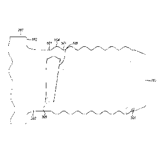
Referring to figures 3 to 6, thread ridge 302 of spigot 208 may be considered
to comprise a
plurality of helical turns each turn extending 360 externally over spigot 208
around a
CA 02986619 2017-11-21
WO 2016/188857 PCT/EP2016/061292
-11-
central axis 304 of the adaptor 100. Accordingly, each turn may be considered
to comprise
an axial and circumferential start 601 and a corresponding axial and
circumferential end
602 as illustrated in figure 6. Each of the helical turns comprise a crest 500
and a
corresponding root 501 with the crest and roots 500, 501 separated by
respective flaffl(s
502a, 502b. Each flaffl( 502a, 502b extends axially between a crest 500 and an
adjacent
root 501 being aligned generally transverse to axis 304. Accordingly, each
flaffl( 502a,
502b is formed as an inclined and declined curved surface 600a, 600b that
provides a
smooth transition between each of the crests 500 and the axially neighbouring
roots 501.
Referring to figure 5, threaded section 204 comprises a plurality of axially
inner helical
turns 505, a first axially endmost turn 503 (that terminates at conical
section 303) and a
second endmost turn 504 (that terminates at non-threaded shank 203). According
to the
specific implementation, the shape, dimensions and/or configurations of the
endmost
helical turns 503, 504 are different to the axial inner helical turns 505 and
are configured
specifically to reduce stress concentrations at the threaded section 204
resultant from
bending forces. In particular a depth 506 of the thread, corresponding to the
radial distance
between root 501 and crest 500, diminishes at each endmost helical turn 503,
504 relative
to the depth 506 at the innermost helical turns 505. Referring to figure 7,
the axially inner
endmost helical turn 504 comprises a transition region indicated generally be
reference 700
within which the thread depth 506 of the ridge 302 decreases from the level of
the axially
inner helical turns 505 to zero. Transition region 700, according to the
specific
implementation, extends circumferentially over a distance in a range 0.2 to
0.3 (90
degrees) of a full helical turn as defined between the turn start and end 601,
602.
Transition region 700 is defined circumferentially by a transition start 802
and a transition
end 803. Region 700 is defined axially so as to encompass the axially endmost
flank 502c
positioned axially closest to non-threaded shank 203 and an axially innermost
flank 502d
positioned axially closest to the axially inner helical turns 505.
Accordingly, transition
region 700 extends axially between axial neighbouring roots 501.
Referring to figure 8, thread depth 506 decreases from transition start 802 to
transition end
803 whilst the pitch of the thread (as defined between axially neighbouring
crests 500) is
maintained constant over the full axial length of threaded section 204. The
thread depth at
CA 02986619 2017-11-21
WO 2016/188857 PCT/EP2016/061292
-12-
transition start 802 is approximately equal to the thread depth 506 at the
axially inner
helical turns 505 and a thread depth 506 at transition end 803 is zero (or
substantially
zero). The axially endmost helical turn 504 within the transition region 700
comprises a
crest 500 bordered at each axial side by two asymmetric flaffl(s 502c, 502d.
In particular,
inner flaffl( 502d comprises an axial length 801 that is generally greater
than a
corresponding axial length 800 of the endmost flaffl( 502c, with this relative
difference
extending over the full circumferential length of the transition region 700
between start
802 and end 803. In particular, the circumferential path of the endmost
flaffl( 502c is
angled or curved in the circumferential path of the thread towards crest 500
such that the
axial length 800 of the endmost flaffl( 502c decreases at a rate that is
greater than that of the
inner flank 502d as the thread depth decreases from transition start 802 to
transition end
803. Accordingly, a region 804 is created to the innermost axial side of inner
flank 502c
that comprises an external diameter being approximately equal to the external
diameter of
non-threaded shank 203. As such, it may be considered that the non-threaded
shank 203 is
extended axially into the threaded section 204 as the thread, at end 300, is
truncated by the
change in the shape profile and the orientation of the endmost flank 502c.
According to
the specific implementation, an axial length of flank 502c at a mid-
circumferential point of
transition region 700 (midpoint between start 802 and end 803) is
approximately 0.4 to 0.7
of the corresponding axial length of inner flank 502d. Accordingly, a
circumferential path
of axially endmost flank 502c of the endmost helical turn 504 is aligned non-
parallel or
transverse to i) the circumferential path of inner flank 502d within the
transition region 700
and ii) the corresponding flanks 502a, 502b of the axially inner helical turns
505.
A further specific implementation of the male spigot 208 is detailed with
reference to
figure 9. Figure 9 differs from the embodiment shown and described with
reference to
figures 1 to 8 in that the non-threaded shank 203 comprises a continuously
curved shape
profile in the axial direction between side face 102 and the thread end 300.
However, the
configuration of the threaded section 204 described below according to the
embodiment of
figure 9 is applicable also to the embodiment of figures 1 to 8.
Referring to figure 9 and to optimise the strength of the spigot 208 for
resistance to
bending forces encountered by the drill string during percussive drilling, the
quotient
CA 02986619 2017-11-21
WO 2016/188857 PCT/EP2016/061292
-13-
Ls/Dy is in a range 0.4 to 1.0 and according to the specific implementation is
0.5 to 0.7,
where Ls corresponds to an axial length of the non-threaded shank 203 defined
between an
axially inner end of the threaded section 300 and side surface 102; and Dy
corresponds to
the diametric distance between the radial positions of the crests 500 on
diametrically
opposite sides of the threaded section 204. Additionally and as detailed
herein, Lt
corresponds to an axial length of threaded section 204 and Di corresponds to
the diametric
distance between the radial positions of the roots 501 (between each helical
ridge) on
diametrically opposite sides of the threaded section 204. Moreover, Td
corresponds to a
depth of the thread between crests 500 and roots 501 in a plane perpendicular
to
longitudinal axis 309.
The strengthening of the spigot 208 may be expressed as the quotient Ls/L
being in the
range 0.25 to 0.5 and in particular 0.28 to 0.32. Additionally, enhancing the
axial length
Ls of the non-threaded shank 103 such that Lt is greater than Ls is
advantageous to
separate axially the threaded section 204 from annular side surface 102 that
has been found
through simulation investigations to minimise the stress at the helical turns
and in
particular the crests 500, roots 501 and flanks 502a, 502b for shoulder
contact threaded
couplings. Accordingly, the risk of failure of the coupling joint is minimised
and the
operational lifetime of the drill string components enhanced.
Threaded section 204 is formed as a generally cylindrical end section at
spigot 208 such
that the diameter Dy of the thread between crest 500 is generally uniform
along the axial
length of threaded section 204. Additionally, a diameter Di is also
substantially uniform
along the full axial length of the threaded section 204 between thread ends
300, 301. The
subject invention is specifically adapted for percussion (or hammer)
components forming
part of a drilling apparatus and in particular a drill string by virtue of the
configuration of
the thread at the spigot 208. In particular, a pitch length of the thread may
be in the range
5 to 50 mm depending upon the size (i.e., radius) of the elongate component.
To optimise
the thread for percussion drilling, a pitch angle 0 may be in the range 5 to
100 for
respective sizes of component. Such a configuration is to be contrasted with
component
threaded ends for rotary or exploration that may typically comprise API type
threads
having a much reduced pitch angle being of the order of 10. In some
implementations, an
CA 02986619 2017-11-21
WO 2016/188857 PCT/EP2016/061292
-14-
average thread diameter (crest-to-crest distance) may be in the range 15 to
120 mm being
dependent upon the size (i.e., radius) of the elongate component.
Accordingly, the thread at the male spigot preferably comprises a quotient of
pitch (crest to
crest axial distance)/average thread diameter of 0.35 to 0.55 where the
average thread
diameter is the average of diameter of the male and female threaded ends.
The present male spigot is also configured to minimise stress concentrations
at transition
regions 900, 901, 902, 904 where such transition regions are positioned
axially between
threaded section 204 and shoulder 207 and in particular represent an axial
portion of the
non-threaded shank 203 that transitions from side surface 102 at shoulder 207.
According
to the specific implementation, non-threaded shank 203 comprises a transition
region 900
to 904 at the junction with side surface 102 that increases in diameter from a
minimum
diameter Ds (of the non-threaded shank 203) according to a curved shaped
profile.
Additionally, the stress concentrations at the region around non-threaded
shank 203 and
threaded section 204 are further minimised by virtue of the relative
dimensions of Ds, Di
and Td. In particular, the stress concentrations at transition region 900 to
904 are
minimised as far as possible where Ds is less than Dy and Ds is less than Di.
In particular,
a maximum diameter Ds may be equal to Di ¨ Td and a minimum diameter Ds may be
equal to Di - 4Td. Preferably, Ds is approximately equal to Di - 2Td.
The relative dimensions of Ds and Ls as described herein maximise the axial
and radial
distances over which the transition region 900 to 904 may extend. In
particular, and
according to the configuration of figure 9, the non-threaded shank 203
comprises a
transition region having a first radius of curvature R1 at section 900 that is
less than a
second axially adjacent radius of curvature R2 at section 901 that is in turn
less than an
axially adjacent third radius of curvature R3 at section 902 that is in turn
less than an
axially adjacent fourth radius of curvature R4 at section 904. In particular,
the radius R1 at
section 900 is approximately equal to half the radius R2 at section 901; the
radius R2 at
section 901 is approximately half the radius R3 at section 902 and the radius
R3 at section
902 is approximately one third of the radius R4 at section 904. As illustrated
in figure 9,
section 900 is positioned axially closest to side surface 102, section 901 is
positioned
second closest to side surface 102, section 902 is positioned third closest to
side surface
CA 02986619 2017-11-21
WO 2016/188857
PCT/EP2016/061292
-15-
102 and section 904 is positioned furthest from side surface 102. A minimised
Ds and a
maximised Ls accordingly enable a smooth transition between the non-threaded
shank 203
and the shoulder 207. As such, spigot 208 is strengthened against bending
induced stress
and the stresses resultant from transmission of the percussive shock wave.