Note: Descriptions are shown in the official language in which they were submitted.
CA 02987012 2017-11-23
WO 2016/189459 PCT/1B2016/053032
1
APPARATUS FOR SELECTING HORTICULTURAL PRODUCTS
The present invention relates to an apparatus for selecting
horticultural products.
As is known, large companies dedicated to the distribution and
marketing of horticultural products are often equipped with lines that are at
least partially automated and are capable of transporting, checking and/or
packaging a large number of products of interest in the unit time.
Known lines are therefore already capable of performing several
activities, such as for example washing, defect checking (and/or rejection or
reprocessing of defective units), packaging and calibration, a term used to
reference the selection of the horticultural products as a function of their
dimensions.
It should be noted in this regard that calibration has a primary role in
the automatic lines outlined so far, since even when they are intended for a
single specific horticultural product (be it fruit or vegetable) they receive
the
goods to be processed directly from the harvesting fields and are therefore
fed with indiscriminate masses of mutually heterogeneous products.
Along the lines, therefore, there are stations capable of selecting
automatically the products as a function of the dimensions, in order to
assign them to different downstream stations (which are thus fed with
mutually homogeneous products) and/or package them in different packages
as a function of their size.
Indeed due to the importance of this function (performed by stations
that perform the desired selection mechanically or electronically), and due
to the heterogeneous nature of the goods, the most modern lines have,
upstream of the calibration station, an additional ("pre-calibration")
station,
which performs a preliminary selection of the horticultural products.
In greater detail, and with specific reference to lines dedicated to
cherries, in the pre-calibration stations a stream of water that entrains with
it
the cherries to be selected affects a plurality of suspended cylinders, which
CA 02987012 2017-11-23
WO 2016/189459 PCT/1B2016/053032
2
are mutually parallel and rotate about their own axis.
The cylinders are inclined (downstream) and appropriately mutually
spaced and contoured, so that a longitudinally oriented slot is formed
between each pair of adjacent cylinders.
In this manner, as soon as as the stream strikes the cylinders, the
water, any leaves, sterns and other debris fall directly below; minimum-size
cherries (i.e., the only ones which, due to their small dimensions, are able
to
pass through the slot) may further fall slightly further on. Vice versa, the
largest cherries continue their travel, sliding along the lateral surfaces of
the
cylinders (which rotate indeed to facilitate advancement) until they fall
downstream of said cylinders.
Thus, in addition to removing leaves and other debris, the station
performs a first division of the cherries into two groups (indeed as a
function of dimensions), each of which is collected in a respective tank
filled with water, which is of course arranged below the cylinders and
makes the respective cherries available to the actual calibration stations.
However, this constructive solution is not devoid of drawbacks.
It should in fact be noted that in known pre-calibration stations the
rotation of the cylinders is entrusted to a motor that actuates a series of
gears, with which respective pins which protrude coaxially from the end
directed downstream of the cylinders.
This configuration forces the need to keep the cylinders at a vertical
level that is significantly higher than the level at which the upper edge of
the collection tanks is located.
Only in this manner the motor and the gears that are responsible for
the movement of the cylinders (indeed located below the lower ends of said
cylinders) can find an adequate placement without having to be themselves
immersed in the water of the tanks (an obviously unacceptable condition).
However, this entails a considerable leap for the cherries, when they
fall from the slot or from the lower end of the cylinders into said tanks.
CA 02987012 2017-11-23
WO 2016/189459 PCT/1B2016/053032
3
Although this usually is not a problem (due to the low weight) for the
smallest cherries, the excessive leap is instead a highly unwelcome
drawback for larger ones (which, as shown, slide along the entire length of
the cylinders and fall beyond).
Larger cherries can in fact fall onto other cherries that are floating in
the tank, bruising each other or otherwise becoming damaged, causing in
any case a degree of defectiveness that is now unacceptable.
The aim of the present invention is to solve the problems described
above, by providing an apparatus that allows optimum preliminary selection
(pre-calibration) of cherries or other horticultural products.
Within this aim, an object of the invention is to provide an apparatus
that is capable of performing the preliminary selection (pre-calibration)
without damaging or deteriorating the treated horticultural products, be they
cherries or others.
Another object of the invention is to provide an apparatus that is
capable of performing the preliminary selection (pre-calibration) without
forcing leaps of excessive extent on the treated horticultural products, be
they cherries or others.
Another object of the invention is to provide an apparatus that ensures
high reliability in operation.
Another object of the invention is to provide an apparatus that can be
obtained easily starting from commonly commercially available elements
and materials.
Another object of the invention is to provide an apparatus that has
low costs and is safe in application.
This aim, as well as these and other objects that will become better
apparent hereinafter, are achieved by an apparatus for selecting horticultural
products, comprising an intake section for horticultural products, which
leads to at least one passage lane defined by a pair of mutually close stems
that are supported rotatably by a respective support and movement assembly
CA 02987012 2017-11-23
WO 2016/189459 PCT/1B2016/053032
4
and are interposed longitudinally between said intake section and a
discharge Section, between said at least one pair of sterns, kept inclined
downward from said intake section to said discharge section, there being a
longitudinal slot that can be crossed exclusively by debris and horticultural
products having dimensions that are smaller than the width of said slot,
characterized in that said assembly comprises a drive unit which meshes,
optionally indirectly, with a first end portion of each one of said stems that
is proximate to said intake section, and respective elements for the free
support of a second end portion of each one of said sterns that is proximate
to said discharge section.
Further characteristics and advantages of the invention will become
better apparent from the description of a preferred but not exclusive
embodiment of the apparatus according to the invention, illustrated by way
of nonlimiting example in the accompanying drawings, wherein:
Figure 1 is a top view of an apparatus according to the invention;
Figure 2 is a side elevation view of the apparatus according to the
invention;
Figure 3 is a sectional view of Figure 1, taken along the line
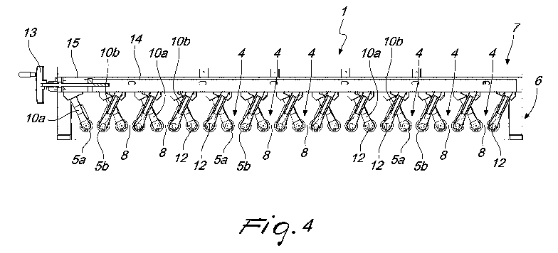
Figure 4 is a sectional view of Figure 2, taken along the line IV-IV.
With particular reference to the cited figures, the reference numeral 1
generally designates an apparatus for selecting horticultural products, which
comprises first of all an intake section 2 for said horticultural products.
It is specified that the apparatus I can find application in any point of
lines for the processing of horticultural products (of any type), where indeed
the need arises to divide them into at least two subgroups (indeed select
them) as a function of their dimensions.
It should be noted, further, that the transport of the horticultural
products along the path defined by the apparatus 1 can be entrusted
exclusively to the force of gravity or be obtained in other manners, but in
the preferred application these products are propelled by a fluid under
CA 02987012 2017-11-23
WO 2016/189459 PCT/1B2016/053032
pressure (preferably water) (which therefore cooperates with the force of
gravity).
In the accompanying figures, for example, a constructive solution is
proposed in which at the intake section 2 the products are in practice
5 delivered from a distribution and conveyance tank 3 (which divides the
horticultural products on a plurality of uniform rows indeed to facilitate the
correct operation of the apparatus 1).
It is specified further right now that in the preferred application, to
which reference shall be made often in the continuation of the present
description, the horticultural products treated (selected) by the apparatus 1
are cherries, but it is useful to specify again that this does not exclude the
use of said apparatus 1 in relation to different types of fruit or vegetable.
In any case, the intake section 2 leads in an upward region to at least
one passage lane 4 that is defined by a pair of mutually close stems 5a, 5b.
The sterns 5a, 5b are supported rotatably by a respective support and
movement assembly 6 and are interposed longitudinally between the intake
section 2 and a discharge section 7 (which substantially corresponds to the
section of Figure 4).
Furthermore, between the pair of stems 5a, 5b, which are kept
inclined downward from the intake section 2 to the discharge section 7
(therefore from upstream to downstream), there is a longitudinal slot 8 that
can be crossed only by debris and horticultural products that have
dimensions that are smaller than the width of such slot 8.
Vice versa, therefore, larger cherries are forced to travel along the
entire lane 4 (or in any case to continue until they reach a point of the slot
8
that has a greater width) and therefore fall further downstream.
It should be noted that the components and the operation outlined
above therefore allow to perform the desired selection: as soon as the stream
of water and cherries strikes the sterns 5a, 5b, the leaves, sterns and other
small debris fall immediately through the slot 8; the smaller cherries also
CA 02987012 2017-11-23
WO 2016/189459 PCT/1B2016/053032
6
fall with them (or directly after) and thus fall, for example, into a first
collection tank.
On the other hand, the larger cherries continue their travel and fall
further downstream into a second collection tank.
From the two collection tanks the cherries can then be picked up by
different devices and/or be intended for different treatments, as a function
of
the different dimensions.
The apparatus 1 in practice preferably performs a pre-calibration
function, understood indeed as a first preliminary division of a chaotic mass
of cherries into two at least partially homogeneous subgroups.
According to the invention, the assembly 6 comprises a drive unit 9
which meshes, optionally indirectly (i.e., by means of respective
transmission elements), with a first end portion of each stern 5a, 5b
proximate to the intake section 2.
Furthermore, the assembly 6 comprises respective elements 10a, 10b
for the free support of a second end portion of each stem 5a, 5b directed
toward the discharge section 7.
It should be noted that the methods for movement and support of the
stems 5a, 5b indicated above allow right now to achieve the intended aim:
the (bulky) elements that are responsible for moving the sterns 5a, 5b are in
fact now arranged proximate to the intake section 2, at which the sterns 5a,
5b (with their first end portion, to which indeed said elements are
connected) have a higher vertical elevation.
Vice versa, at the second end portion, arranged at a lower vertical
height, the sterns 5a, 5b are simply supported by the elements 10a, 10b
having a reduced space occupation and besides, as will become apparent
hereinafter, they can be arranged above said stems 5a, 5b.
Therefore, in the apparatus 1 according to the invention a free space
of considerable extent is not required below the lower flap of the sterns 5a,
5b, which can thus be kept proximate to the underlying collection tanks,
CA 02987012 2017-11-23
WO 2016/189459 PCT/1B2016/053032
7
thus effectively reducing the leap that is imposed on the cherries and indeed
achieving the intended aim.
In particular, the apparatus 1 comprises a plurality of lanes 4, which
are defined by respective pairs of adjacent sterns 5a, 5b, which are
supported rotatably by the assembly 6 and are interposed longitudinally
between the sections 2, 7 (from upstream to downstream). As can be
deduced also from the accompanying figures, respective longitudinal slots 8
are therefore defined between pairs of adjacent stems 5a, 5b.
As clearly shown by Figures 1 and 4, in the configuration that is
proposed (by way of nonlimiting example) each stern designated by 5a is
alternated with a respective stern, designated by 5b, and for an observer
located downstream (Figure 4) the lanes 4 and the slots 8 are defined
exclusively to the right of each stern 5a (and correspondingly to the left of
each stem 5b), while the space directly to the left of each stem 5a is unused.
It is useful to specify again in any case that use in different manner of
the various interspaces defined between the stems 5a, 5b as a function of the
specific requirement is not excluded.
In the preferred embodiment, shown in the accompanying figures by
way of example of the invention, an output shaft 9a of the drive unit 9 (for
example an electric motor) is connected, optionally by means of respective
Gears to a motion transmission shaft 11.
The transmission shaft 11 in turn is coupled, optionally indirectly
(therefore optionally by means of additional gears), to each first end portion
of the sterns 5a, 5b, so as to indeed give them the desired rotary motion
about their own axis (which is required to facilitate the sliding of the
largest
cherries along the respective lateral surfaces and thus make them fall
downstream).
In an embodiment of considerable practical interest, mentioned by
way of nonlimiting example, each element 10a, 10b for free support is
constituted substantially by a respective arm, which is indeed adapted to
CA 02987012 2017-11-23
WO 2016/189459 PCT/1B2016/053032
8
support the respective stem 5a, 5b from above.
As clearly shown for example by Figure 4, each arm is in fact
anchored in an upward region to the support and movement assembly 6 and
is provided in a downward region with a seat 12 for rotary accommodation
for the respective second end portion of a corresponding stem 5a, 5b.
Furthermore, usefully each arm (each element 10a, 10b) is inclined
with respect to the vertical: as can be deduced also from Figure 3, with this
configuration each arm remains spaced from the respective (end) portion of
the passage lane 4, which in practice corresponds substantially to the region
of space that is interposed between the corresponding lateral surfaces of the
second end portions of the stems 5a, 5b.
In this manner the danger that the cherries in transit might strike the
arms, becoming damaged and/or diverting from the preset trajectory, is
avoided.
Conveniently, the apparatus 1 according to the invention comprises
means for the adjustment of the position of at least one stem 5b, so as to be
able to vary selectively the shape and/or width of the respective slot 8.
It should be noted that this possibility increases significantly the
versatility of the apparatus 1 according to the invention, since by acting on
the adjustment means (for example in the manners that will be described
hereinafter) it is possible to change the dimensional limit (the width of the
slots 8) that discriminates between the cherries that are able to pass through
said slots 8 and the ones that instead travel along the entire lane 4.
Besides,
by way of the adjustment means and thanks to the possibility to vary the
shape and dimensions of the slots 8 it is also possible to reconfigure such
apparatus 1 according to the invention to select a different type of fruit (or
other horticultural product in general) to be divided according to different
dimensional criteria.
In particular, in the constructive solution proposed therefore in the
accompanying figures by way of example, the means comprise a first
CA 02987012 2017-11-23
WO 2016/189459 PCT/1B2016/053032
9
actuation unit 13 (a first knob that can be operated by the user) for
actuating
the transverse movement of a slider 14 that is integral with at least one
supporting arm of the second end of a corresponding stern 5b.
By means of the transverse movement (i.e., substantially horizontally
and at right angles to the longitudinal extension of the sterns 5a, 5b) it is
thus possible to change (albeit slightly) the inclination of the stems 5b and
therefore achieve the consequent variation of the shape and/or width of the
respective slot 8 (for example keeping the corresponding adjacent stern 5a
fixed).
In particular, each pair of stems 5a, 5b that defines a respective slot 8
is composed of a first stem 5a (on the left, for an observer located
downstream) and a second stem 5b (on the right for a downstream
observer). The first stern 5a is therefore supported in the corresponding
second end by a corresponding arm (element 10a) that is anchored in an
upward region to a fixed cross-member 15 defined by the support and
movement assembly 6. Vice versa, the second stern 5b is supported in the
corresponding second end by a corresponding arm (element 10b) that is
anchored in an upward region to the slider 14 and is guided slidingly by said
cross-member 15 (or by another fixed element of the support and movement
assembly 6).
It should be noted therefore that by acting exclusively on the second
end portions of the sterns 5b it is possible to vary the shape of the
respective
slot 8, increasing or decreasing the width of the upstream portion with
respect to the width of the downstream portion, as a function of the specific
requirements.
The means may further comprise a second actuation unit 16 (a second
knob), which can be activated by a user for the transverse movement of the
first end of a respective stem 5a, 5b and the consequent variation of the
shape and/or width of the respective slot 8.
It should be noted first of all that the provision of apparatuses 1
CA 02987012 2017-11-23
WO 2016/189459 PCT/1B2016/053032
lo
according to the invention provided with adjustment means that act
exclusively on the first end portions (or also on others as well) as a
function
of the specific requirements is not excluded.
However, in the embodiment proposed in the accompanying figures,
the adjustment means comprise both the first actuation unit 13 and the
second actuation unit 16: this evidently ensures maximum versatility to the
apparatus 1.
The manners in which the second actuation unit 16 adjusts the
movement of the first end portions of the sterns 5a, 5b may be similar to the
ones described in relation to the first actuation unit 13 or may be different
according to the specific requirements.
Usefully, each stem 5a, 5b has a cylindrical shape, although it is not
excluded to adopt different shapes and contours, for example conical ones,
to define slots 8 having different shapes.
If therefore the stems 5a, 5b have such cylindrical shape (and
mutually parallel axes) they may define slots 8 that have a constant width:
by imposing the same displacement to the first and second end portions (by
means of the units 13, 16), it is therefore possible to vary uniformly such
width along its entire longitudinal extension. Vice versa, with displacements
of different extent, or by acting on just one of the units 13, 16, it is
possible
to shape the slots 8 differently, so that for example they widen downstream.
Operation of the apparatus according to the invention is as follows.
Upstream of the apparatus 1, the cherries are redistributed in various
channels by way of the distribution and conveyance tank 3, from which
therefor the cherries fall in tidy rows into the passage lanes 4,
substantially
at the intake section 2.
As shown, each passage lane 4 is affected, along the entire length, by
a respective slot 8 that is delimited by adjacent stems 5a, 5b: debris of
various kinds, optionally entrained by the water together with the cherries,
can thus fall immediately through the slot 8.
CA 02987012 2017-11-23
WO 2016/189459 PCT/1B2016/053032
I I
The smallest cherries also fall together with the debris (or shortly
thereafter), while the larger cherries advance along the lane 4 to fall
further
downstream, at an optional widening of the slot 8 or .simply beyond the
discharge section 7 and the stems 5a, 5b. The apparatus 1, in other words,
performs selection by making cherries of different sizes fall automatically in
different points of the line.
By way of the choice to connect the drive unit 9 to the first end
portion (arranged at a higher level) of each stem 5a, 5b, and by resorting to
simple supporting elements 10a, 10b for the second end portions, in
particular the latter and in general the entire stems 5a, 5b can be kept
proximate to the free surface of the water that fills the underlying
collection
tanks.
This positive effect is increased by the preferred choice of supporting
from above the second portions by means of elements 10a, 10b, which in
turn are fixed in an upward region to the support and movement assembly 6
(to the cross-member 15 or to the slider 14).
In this configuration the second portions of the stems 5a, 5b in fact
can be kept even closer to the collection tanks, until they almost skim them,
without compromising in any way the correct operation of the apparatus 1.
Moreover, a very small leap (from the slot 8 to the collection tank) is
imposed on the cherries, its value being however particulary modest for
larger fruits (the ones for which the risk of bruising is higher), which
indeed
fall proximate to the discharge section 7 (of the second end portions of the
stems 5a, 5b), kept at the lowest vertical height.
The configuration obtained above therefore allows to perform the
selection (calibration) without subjecting the treated horticultural products,
be they cherries or others, to the risk of impacts, bruising or damage in
general and therefore without deteriorating them in any way (as instead
occurs with known apparatuses due to the excessive leap that is imposed).
Moreover, it is stressed that the adjustment means can provide further
CA 02987012 2017-11-23
WO 2016/189459 PCT/1B2016/053032
1")
functionalities to the apparatus 1 according to the invention, ensuring in
fact
the possibility to vary at will the selection parameters (the discriminating
dimensional limit for the division of the cherries into dimensionally uniform
subgroups).
Finally, it is specified again that the apparatus 1 according to the
invention ensures the preservation of the quality of the treated horticultural
products (without causing damage or bruising) also by way of the choice to
arrange at an angle (in a V-shaped configuration) the sterns 5a, 5b that
define the slots 8 and the lanes 4, since in this configuration they do not
hinder the advancement of the cherries.
In practice it has been found that the apparatus according to the
invention achieves fully the intended aim, since resorting to a support and
movement assembly that comprises a drive unit that meshes with a first end
portion of the sterns that define the slots, proximate to the input section,
and
respective elements for the free support of a second end portion of such
sterns that is proximate to the discharge section allows to perform the
optimum preliminary selection (pre-calibration) of cherries or other
horticultural products.
The invention thus conceived is susceptible of numerous
modifications and variations, all of which are within the scope of the
appended claims; all the details may further be replaced with other
technically equivalent elements.
In the examples of embodiment shown, individual characteristics,
given in relation to specific examples, may actually be interchanged with
other different characteristics that exist in other exemplary embodiments.
In practice, the materials used, as well as the dimensions, may be any
according to requirements and to the state of the art.
The disclosures in Italian Patent Application no. 102015000018551
(UB2015A001233), from which this application claims priority, are
incorporated herein by reference.
CA 02987012 2017-11-23
WO 2016/189459 PCT/1B2016/053032
13
Where technical features mentioned in any claim are followed by
reference signs, those reference signs have been included for the sole
= ,purpose of increasing the intelligibility of the claims and accordingly
such
reference signs do not have any limiting effect on the interpretation of each
element identified by way of example by such reference signs.