Language selection

Search

Patent 2987694 Summary

Third-party information liability

Some of the information on this Web page has been provided by external sources. The Government of Canada is not responsible for the accuracy, reliability or currency of the information supplied by external sources. Users wishing to rely upon this information should consult directly with the source of the information. Content provided by external sources is not subject to official languages, privacy and accessibility requirements.

Claims and Abstract availability

Any discrepancies in the text and image of the Claims and Abstract are due to differing posting times. Text of the Claims and Abstract are posted:

  • At the time the application is open to public inspection;
  • At the time of issue of the patent (grant).
(12) Patent Application: (11) CA 2987694
(54) English Title: DRIVE FOR A TRACK-GUIDED VEHICLE
(54) French Title: ENTRAINEMENT POUR UN VEHICULE GUIDE
Status: Deemed Abandoned and Beyond the Period of Reinstatement - Pending Response to Notice of Disregarded Communication
Bibliographic Data
(51) International Patent Classification (IPC):
  • B61B 13/04 (2006.01)
(72) Inventors :
  • CLAAS, DIX (Germany)
  • CLAAS, BENEDIKT (Germany)
(73) Owners :
  • DIX CLAAS
  • BENEDIKT CLAAS
(71) Applicants :
  • DIX CLAAS (Germany)
  • BENEDIKT CLAAS (Germany)
(74) Agent: KIRBY EADES GALE BAKER
(74) Associate agent:
(45) Issued:
(86) PCT Filing Date: 2015-06-23
(87) Open to Public Inspection: 2016-12-29
Availability of licence: N/A
Dedicated to the Public: N/A
(25) Language of filing: English

Patent Cooperation Treaty (PCT): Yes
(86) PCT Filing Number: PCT/EP2015/064119
(87) International Publication Number: WO 2016206727
(85) National Entry: 2017-11-29

(30) Application Priority Data: None

Abstracts

English Abstract

The invention relates to a drive for a vehicle which is track-guided on a track section (3), said vehicle being supported on the track section (3) by track rollers (6) when at a standstill or when moving slowly. Lift-causing elements (11) are mounted on the vehicle and lift the vehicle off the track section (3) during fast travel, and drive rollers (2) of the vehicle act laterally on the track section (3).


French Abstract

La présente invention concerne un entraînement pour un véhicule guidé sur une voie (3), qui repose sur la voie (3) à l'aide de galets de roulement (6) lorsqu'il est à l'arrêt ou qu'il roule lentement. Selon l'invention, ledit véhicule comporte des éléments de portance (11) qui soulèvent le véhicule de la voie (3) lorsque le véhicule roule à grande vitesse, et des galets d'entraînement (2) qui viennent en contact latéralement avec la voie (3).

Claims

Note: Claims are shown in the official language in which they were submitted.

7
Claims:
1. Drive for a vehicle which is track-guided on a track section (3), which at
a standstill and
when traveling slowly is supported by track rollers (6) on the track section
(3),
characterized in that
buoyancy elements (11) are mounted on the vehicle which lift the vehicle above
the track
section (3) during fast travel, and drive rollers (2) of the vehicle laterally
act on the track
section (3).
2. Drive according to claim 1, characterized in that the track section (3)
comprises at least
one rail (4).
3. Drive according to claim 2, characterized in that in the raised position,
the track roller (6)
is farther pressed against the associated rail (4).
4. Drive according to claim 1, characterized in that the track section (3) is
an upright track
section of rectangular cross section.
5. Drive according to claim 1, characterized in that the buoyancy elements
(11) are wings
that are connected to the housing (1) of the vehicle.
6. Drive according to claim 5, characterized in that the wings (11) are
extendable.
7. Drive according to claim 5, characterized in that the wings (11) are
mounted in
air conduits of the housing (1).
8. Drive according to claim 1, characterized in that the drive wheels (2) are
pressed against
the track section (3) by a pressure cylinder (7).
9. Drive according to claim 8, characterized in that on each side of the track
section (3), the
drive wheels are in duplicate, positioned one above the other.

8
10. Drive according to claim 1, characterized in that limiting profiles (5)
are mounted on the
track section (3) which limit upward movement of the vehicle.
11. Drive according to claim 1, characterized in that the drive wheels (2) are
mounted in a
lower tunnel (10) of the housing (1), through which the track section (3)
runs.
12. Drive according to claim 1, characterized in that the drive wheels are
mounted on a
chassis on which the adjacent housings (1) of the railroad cars of an
articulate train are
supported.

Description

Note: Descriptions are shown in the official language in which they were submitted.


CA 02987694 2017-11-29
W02016/206727 1
PCT/EP2015/064119
Drive for a track-guided vehicle
The invention relates to a drive for a vehicle which is track-guided on a
track section, said
vehicle being supported on the track section by track rollers when at a
standstill and when
traveling slowly.
The movement of track-guided vehicles, such as railroad cars, is opposed by
different forces.
These include the frictional forces of a wheel / rail system. To deliver the
driving forces to the
rail via non-positive friction, the vehicles must be heavy. It has therefore
long been a desire to
provide a modified drive without power transmission via non-positive friction.
This has led to
the development of the magnetic levitation train, in which the railroad cars
float over the track
section contact-free and are driven by a linear motor. The technology of the
magnetic levitation
train is very energy-consuming since large electromagnets constantly have to
be energized. Also,
production of the track section is very expensive.
From the automotive industry it is known to optimize the aerodynamic
properties of a vehicle in
order to save driving power. To this end, spoilers and similar components are
used.
It is the object of the invention to propose a drive for a track-guided
vehicle, in which the energy
required, as compared to conventional vehicles, is significantly reduced and
thus allows for
easier construction of the vehicle and a single track section.
This object is achieved by a drive according to claim 1. Advantageous
embodiments are
specified in the dependent claims.
A drive for a track-guided vehicle, in particular a railroad car, is proposed,
which is guided on a
track section. The vehicle is supported on the track section by track rollers
when at a standstill
and when traveling slowly.

CA 02987694 2017-11-29
W02016/206727 2
PCT/EP2015/064119
The vehicle is characterized in that attached thereto are buoyancy elements
that raise the vehicle
above the track section during fast travel, and drive rollers of the vehicle
act laterally on the track
section.
By means of the buoyancy elements, the vehicle experiences an upward force
that raises it a bit
above the track section. This way, the driving force required for the
propulsion of the vehicle is
significantly reduced.
The vehicle is guided on the track section by the drive wheels acting
laterally on the track
section. These act both when traveling slowly, when the vehicle is supported
by the track rollers,
as well as in the raised position.
The track section is designed such that it has at least one rail.
In one embodiment, a single rail itself may be the track section and the drive
wheels are pressed
against it by means of actuating cylinders. If the drive wheels are in
duplicate on each side of the
track section, the necessary force can be applied for lateral stabilization.
Guidance of the vehicle on the rail is further improved when even in the
raised state, the track
roller is pressed against the rail with a spring.
In another embodiment, the track section is an upright track of rectangular
cross section, on
which two parallel rails are provided. On said rails, the vehicle is supported
by track rollers when
at a standstill and or when traveling slowly.
In this embodiment also, the driving force is applied via drive wheels that
act laterally on the
track section.
During fast travel, the buoyancy force is applied via buoyancy elements, such
as wings, that are
connected to the housing of the vehicle. These can be firmly attached to the
housing of the
vehicle, such as to the roof However, wings that are extended only when the
vehicle travels fast
are also possible.
Another possibility is that air conduits are incorporated in the housing of
the vehicle, in which
the buoyancy elements are positioned.

CA 02987694 2017-11-29
W02016/206727 3
PCT/EP2015/064119
In order to reduce the frictional forces of the vehicle, only a small lifting
of the housing from the
rail is required. However, for the drive wheels not to lose contact with the
track section due to
excess lifting, a height limitation is provided at the track section by means
of limiting profiles.
The housing of the vehicle advantageously clasps around a part of the track
section. To this end,
a tunnel is provided in the bottom of the housing, which is so wide that even
a track section that
is flexed for curves can fit.
The drive proposed herein is also suitable for an articulated train, in which
in each case adjacent
housings of railroad cars rest on a common chassis. On the chassis, the
clutches of the adjacent
cars are attached, which must also ensure the lateral stability of the
housing.
In the figures, an embodiment of the drive is exemplified. The drawing show:
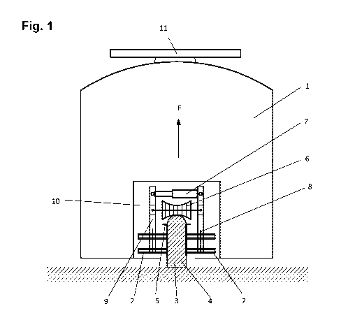
FIG. 1 a schematic cross section through a vehicle with a drive;
FIG. 2 a schematic view of a vehicle on a track section;
FIG. 3 a view of the vehicle from below with the tunnel for the track section;
FIG. 4 a detail of the drive;
FIG. 5 a drive with guide bracket;
FIG. 6 a schematic cross section through a vehicle on a track section having
two rails;
FIG. 7 a schematic view of an articulated train on a track section.
FIG. 1 shows a schematic cross section through a vehicle with its drive. The
track section 3 and
the drive wheels 2 are located in the tunnel 10 in the bottom of the housing
1.
At a standstill of the track roller 6, the housing 1 is held on the track
section 3 which is formed in
this embodiment as a rail 4. On top of the housing, the buoyancy elements 11
are mounted which
generate the buoyancy force F during fast travel. With a sufficiently high
buoyancy force F, the
housing 1 lifts up from the rail 4 by its track roller 6.
On both sides of the track section 3, the drive wheels 2 press on the limiting
profile 5, which
prevent a higher lifting upwards of the housing 1 and thus of the drive wheels
2. The pressure of

CA 02987694 2017-11-29
W02016/206727 4
PCT/EP2015/064119
the drive wheels 2 is provided by the actuating cylinder 7, said wheels
delivering their pressing
force via the push rods 9 and the wheel axles 8 against the drive wheels 2.
FIG. 2 shows a schematic view of a vehicle with its housing 1 on a track
section 3. The track
section 3 passes through the tunnel 10 of the housing 1. Laterally, buoyancy
elements 11 extend
from the housing 11. Furthermore, air inlets 13 are provided, through which
air flows within air
conduits of the housing 1 with buoyancy elements (not shown).
FIG. 3 shows a bottom view of the vehicle with its tunnel 10, through which
the track section 3
extends. The tunnel 10 is kept wide enough for a curved track section to have
sufficient
space. The vehicle is driven by the drive wheels 2, which are laterally
pressed against the track
section 3. The track rollers 6 are positioned over the track section 3 for
support.
FIG. 4 shows a detail of an embodiment of the drive. The drive wheels 2 are
pressed against the
track section 3 via the actuating cylinders 7. They are held by the push rods
9, which are
hingedly connected to the housing 1.
FIG. 5 shows an embodiment of the drive having a guide bracket 14. The guide
bracket 14 is
mounted via the pivot rods 15 on the vehicle and thus can execute a limited
pivoting movement
B. In this way, the drive wheels 2 pressed against the track section 3 can
also bring about an
upward or downward movement A.
The driving force of the vehicle on the track section 3 is applied via the
drive wheels 2, which
are pressed against the track section 3 via the pressure cylinders between the
pressure rods 9 and
the counter supports 16.
FIG. 6 shows a schematic cross section through a vehicle on a wide track
section 3 having two
rails 4, which are guided in parallel. The two track rollers 6 are in the
tunnel 10 of the housing 1,
with which the housing 1 can be supported on the rails 4. The drive wheels 2
are laterally pressed
against the track section 3 via the push rods 9.
In this embodiment, the buoyancy elements 11 are mounted on the roof of the
housing I.

CA 02987694 2017-11-29
W02016/206727 5
PCT/EP2015/064119
FIG. 7 shows a schematic view of an articulated train on a track section 3. In
this case, the by
couplings 12 of the housing 1 of adjacent railroad cars are supported on a
common chassis,
which contains the drive wheels 2.
In this embodiment, the buoyancy elements 11 are fixed on the roofs of the
housing 1.

CA 02987694 2017-11-29
WO 2016/206727 6
PCT/EP2015/064119
Reference numbers
1 housing
2 drive wheel
3 track section
4 rail of the track section
limiting profile
6 track roller
7 pressure cylinder
8 wheel axle
9 push rod
tunnel
11 buoyancy element
12 coupling
13 air inlet
14 guide bracket
pivot rod
16 counter support
A upward and downward movement
pivoting movement

Representative Drawing
A single figure which represents the drawing illustrating the invention.
Administrative Status

2024-08-01:As part of the Next Generation Patents (NGP) transition, the Canadian Patents Database (CPD) now contains a more detailed Event History, which replicates the Event Log of our new back-office solution.

Please note that "Inactive:" events refers to events no longer in use in our new back-office solution.

For a clearer understanding of the status of the application/patent presented on this page, the site Disclaimer , as well as the definitions for Patent , Event History , Maintenance Fee  and Payment History  should be consulted.

Event History

Description Date
Time Limit for Reversal Expired 2020-08-31
Application Not Reinstated by Deadline 2020-08-31
Inactive: COVID 19 - Deadline extended 2020-08-19
Inactive: COVID 19 - Deadline extended 2020-08-06
Inactive: COVID 19 - Deadline extended 2020-07-16
Inactive: COVID 19 - Deadline extended 2020-07-02
Inactive: COVID 19 - Deadline extended 2020-06-10
Common Representative Appointed 2019-10-30
Deemed Abandoned - Failure to Respond to Maintenance Fee Notice 2019-06-25
Change of Address or Method of Correspondence Request Received 2018-01-09
Inactive: Cover page published 2017-12-19
Inactive: Correspondence - PCT 2017-12-15
Inactive: Notice - National entry - No RFE 2017-12-14
Inactive: First IPC assigned 2017-12-11
Inactive: IPC assigned 2017-12-08
Application Received - PCT 2017-12-08
National Entry Requirements Determined Compliant 2017-11-29
Application Published (Open to Public Inspection) 2016-12-29

Abandonment History

Abandonment Date Reason Reinstatement Date
2019-06-25

Maintenance Fee

The last payment was received on 2018-06-13

Note : If the full payment has not been received on or before the date indicated, a further fee may be required which may be one of the following

  • the reinstatement fee;
  • the late payment fee; or
  • additional fee to reverse deemed expiry.

Patent fees are adjusted on the 1st of January every year. The amounts above are the current amounts if received by December 31 of the current year.
Please refer to the CIPO Patent Fees web page to see all current fee amounts.

Fee History

Fee Type Anniversary Year Due Date Paid Date
MF (application, 2nd anniv.) - standard 02 2017-06-23 2017-11-29
Basic national fee - standard 2017-11-29
MF (application, 3rd anniv.) - standard 03 2018-06-26 2018-06-13
Owners on Record

Note: Records showing the ownership history in alphabetical order.

Current Owners on Record
DIX CLAAS
BENEDIKT CLAAS
Past Owners on Record
None
Past Owners that do not appear in the "Owners on Record" listing will appear in other documentation within the application.
Documents

To view selected files, please enter reCAPTCHA code :


To view images, click a link in the Document Description column. To download the documents, select one or more checkboxes in the first column and then click the "Download Selected in PDF format (Zip Archive)" or the "Download Selected as Single PDF" button.

List of published and non-published patent-specific documents on the CPD .

If you have any difficulty accessing content, you can call the Client Service Centre at 1-866-997-1936 or send them an e-mail at CIPO Client Service Centre.


Document
Description 
Date
(yyyy-mm-dd) 
Number of pages   Size of Image (KB) 
Abstract 2017-11-28 1 10
Claims 2017-11-28 2 43
Description 2017-11-28 6 182
Drawings 2017-11-28 5 61
Representative drawing 2017-11-28 1 20
Notice of National Entry 2017-12-13 1 193
Courtesy - Abandonment Letter (Maintenance Fee) 2019-08-05 1 174
International search report 2017-11-28 4 112
National entry request 2017-11-28 3 75
Patent cooperation treaty (PCT) 2017-11-28 1 40
Amendment - Abstract 2017-11-28 1 68
PCT Correspondence 2017-12-14 2 77