Note: Descriptions are shown in the official language in which they were submitted.
MOUNTING SYSTEM FOR LIGHT FIXTURE
FIELD OF THE INVENTION
100011 Embodiments of the invention relate to a light fixture, and more
specifically a
mounting mechanism and method for mounting the light fixture to a wall or
ceiling.
BACKGROUND
[0002] Light emitting diode (LED) light fixtures generally include a
housing, a LED printed
circuit board (PCB) (that includes at least one LED) provided within the
housing, and an optic
coupled to the housing to disperse light generated by the at least one LED as
desired. LEDs are
typically (but not always) driven with direct current (DC) and circuitry can
be provided on the
PCB to convert the incoming alternating current (AC) into DC. Because
installation of the
fixture oftentimes can require access to the compartment of the fixture in
which the PCB resides,
protective barriers are often required on such fixtures to reduce the risk of
inadvertent contact
with the circuitry by an installer.
SUMMARY
100031 The subject matter of examples of the present invention is described
here with
specificity to meet statutory requirements, but this description is not
necessarily intended to limit
the scope of the claims. The claimed subject matter may be embodied in other
ways, may include
different elements or steps, and may be used in conjunction with other
existing or future
technologies. This description should not be interpreted as implying any
particular order or
arrangement among or between various steps or elements except when the order
of individual
steps or arrangement of elements is explicitly described.
[0004] The terms "invention," "the invention," "this invention" and "the
present invention"
used in this patent are intended to refer broadly to all of the subject matter
of this patent and the
patent claims below. Statements containing these terms should be understood
not to limit the
subject matter described herein or to limit the meaning or scope of the patent
claims below.
Embodiments of the invention covered by this patent are defined by the claims
below, not this
summary. This summary is a high-level overview of various embodiments of the
invention and
1
CA 2988325 2017-12-07
introduces some of the concepts that are further described in the Detailed
Description section
below. This summary is not intended to identify key or essential features of
the claimed subject
matter, nor is it intended to be used in isolation to determine the scope of
the claimed subject
matter. The subject matter should be understood by reference to appropriate
portions of the entire
specification of this patent, any or all drawings, and each claim.
[0005] According to some embodiments, a mounting system includes a housing,
a mounting
bracket, and a mounting plate for retaining the housing on a mounting surface,
such as a wall or
ceiling. The housing includes an inner surface and an outer surface. The inner
surface defines a
mounting feature having a flange aperture and a locking feature having a set
screw aperture. The
mounting system includes a mounting bracket and a mounting plate. The mounting
bracket
includes a body, a mounting portion, and a locking portion. The mounting
portion extends from a
first end of the body and is inserted within the flange aperture. The locking
portion extends from
the second, opposing end of the body and engages a set screw extending within
the set screw
aperture.
[0006] According to various embodiments, a method of installing the housing
on a surface
includes securing the mounting system to the surface and mounting the housing
on the mounting
system. Mounting the housing on the mounting system includes: aligning the
distal flange of the
mounting bracket with the flange aperture of the mounting feature defined by
the inner surface of
the housing; inserting the distal flange into the flange aperture; pivoting
the housing towards the
surface and positioning the locking portion of the mounting bracket adjacent
the locking feature
defined by the inner surface of the housing; and securing the housing to the
mounting bracket.
[0007] Various implementations described in the present disclosure can
include additional
systems, methods, features, and advantages, which can not necessarily be
expressly disclosed
herein but will be apparent to one of ordinary skill in the art upon
examination of the following
detailed description and accompanying drawings. It is intended that all such
systems, methods,
features, and advantages be included within the present disclosure and
protected by the
accompanying claims.
BRIEF DESCRIPTION OF THE DRAWINGS
[0008] The features and components of the following figures are illustrated
to emphasize the
general principles of the present disclosure. Corresponding features and
components throughout
2
CA 2988325 2017-12-07
the figures can be designated by matching reference characters for the sake of
consistency and
clarity.
[0009] Figure 1 is a top perspective view of an LED light fixture according
to various
embodiments.
[0010] Figure 2 is a side elevation view of the LED light fixture of Figure
1.
[0011] Figure 3 is a top plan view of the LED light fixture of Figure 1.
[0012] Figure 4 is a cross-sectional view taken along the line Fig. 4- Fig.
4 in Figure 3.
[0013] Figure 5 is a partially exploded perspective view of a mounting
system according to
various embodiments, the mounting system including a mounting plate and a
mounting bracket.
[0014] Figure 6 is a top perspective view of the mounting bracket of the
mounting system of
Figure 5.
[0015] Figure 7 is another top perspective view of the mounting bracket of
the mounting
system of Figure 5.
[0016] Figure 8 is a top plan view of the mounting bracket of the mounting
system of Figure
5.
[0017] Figure 9 is a partially exploded assembly view of the light fixture
of Figure 1 and the
mounting system of Figure 5.
[0018] Figure 10 is a top perspective view of the light fixture of Figure 1
mounted on the
mounting system of Figure 5.
[0019] Figure 11 is a bottom plan view of the light fixture of Figure 1
mounted on the
mounting system of Figure 5.
DETAILED DESCRIPTION
[0020] The subject matter of examples of the present invention is described
here with
specificity to meet statutory requirements, but this description is not
necessarily intended to limit
the scope of the claims. The claimed subject matter may be embodied in other
ways, may include
different elements or steps, and may be used in conjunction with other
existing or future
technologies. This description should not be interpreted as implying any
particular order or
arrangement among or between various steps or elements except when the order
of individual
steps or arrangement of elements is explicitly described.
3
CA 2988325 2017-12-07
[0021] The terms "invention," "the invention," "this invention" and "the
present invention"
used in this patent are intended to refer broadly to all of the subject matter
of this patent and the
patent claims below. Statements containing these terms should be understood
not to limit the
subject matter described herein or to limit the meaning or scope of the patent
claims below.
Examples of the invention covered by this patent are defined by the claims
below, not this
summary. This summary is a high-level overview of various aspects of the
invention and
introduces some of the concepts that are further described in the Detailed
Description section
below. This summary is not intended to identify key or essential features of
the claimed subject
matter, nor is it intended to be used in isolation to determine the scope of
the claimed subject
matter. The subject matter should be understood by reference to appropriate
portions of the entire
specification of this patent, any or all drawings, and each claim.
[0022] Embodiments of the present invention are directed to a mounting
system for light
fixtures and methods of employing the mounting system to align and secure the
light fixture for
wall or ceiling installation. Such mounting systems reduce the risk of injury
due to contact with
the PCB and eliminate the need for the additional barrier by forgoing the need
to access the
compartment of the LED light fixture containing the PCB or any other
electrically charged
components during installation. It should be understood, however, that while
LED light fixtures
are discussed herein, the mounting system disclosed herein is not limited for
use with only LED
light fixtures. Rather, it can be used with any type of surface mounted
fixture, regardless of the
light source within the fixture.
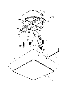
[0023] Figures 1-11 illustrate embodiments of a light fixture 10 with a
mounting system 12
(see Figure 5) for aligning and securing the light fixture 10 on a surface,
such as a wall or a
ceiling, during installation. Although the mounting system 12 is described
below with the light
fixture 10, it will be appreciated that the mounting system 12 are not limited
to use with light
fixtures. In other examples, the mounting system 12 may be used with various
other non-lighting
or non-illuminating components or housings of any kind that are to be mounted
on a surface. For
example, in some embodiments, the mounting system 12 may be used to support a
non-
illuminating component of a lighting system. In some of these embodiments, the
mounting
system 12 may indirectly support the light fixture 10 if the light fixture 10
is attached to the non-
illuminating component, although it need not. As one non-limiting example, the
mounting
system 12 may support an emergency battery backup unit on a surface, and the
light fixture 10
4
CA 2988325 2017-12-07
may be attached to the emergency battery backup unit. In other embodiments,
the mounting
system 12 may be used with various other types of housings or non-illuminating
parts, which
may or may not be part of a lighting system, that are mounted to a surface,
such as emergency
battery backup units, controls, etc. that are mounted on a surface.
[0024] The light fixture 10 includes a housing 14, which may be cast,
molded, or otherwise
formed to have any desired shape. Embodiments of the mounting system 12
described herein are
particularly suitable for use with square fixtures (i.e., the housing 14 is
square). The housing 14
includes an inner surface 20 and an outer surface 22.
[0025] The inner surface 20 of the housing 14 defines a mounting feature 24
and a locking
feature 26 opposite the mounting feature 24. The mounting feature 24 includes
a flange aperture
28, which is dimensioned and configured to accommodate an end of a flange 62
of a mounting
bracket 40 of the mounting system 12, as described in detail below. The
locking feature 26
defines a set screw aperture 30, which is dimensioned to accommodate a set
screw 70 (see
Figures 4 and 9), as described in detail below. In some cases, the set screw
aperture 30 includes
internal threads for interdigitating with the threads on the set screw 70. In
some cases, the set
screw aperture 30 extends from the inner surface 20 to the outer surface 22 of
the housing 14.
[0026] The LEDs 35 are mounted on a support plate 36. The support plate 36
may be
coupled to the housing 14 (such as via fasteners 88 such as screws, bolts,
pins, adhesives, clips,
clasps, snap-fitting, etc.) or may be formed integrally with the housing 14.
Necessary wiring
(incoming power, ground, etc.) may be attached or extend through the support
plate 36.
[0027] The LEDs 35 may be provided on a PCB 18, which is mounted to the
support plate 36
(such as via fasteners 32, such as screws, bolts, pins, etc.). Alternatively,
the LEDs 35 may be
chip-on-board LEDs 35 that are provided directly on the support plate 36. Any
number of PCBs
18 and/or leds 35 may be provided. The LEDs 35 may be single-die or multi-die
leds 35, DC or
AC, or can be organic leds 35. White, color, or multicolor LEDs 35 may be
used. Moreover, the
leds 35 need not be all the same color; rather, mixtures of LEDs 35 may be
used.
[0028] An optic 34 is provided over the LEDs 35 to control the distribution
of light emitted
from the LEDs 35. Any number or type of optic 34 may be used, including, but
not limited to,
extruded or molded lenses, diffusers, collimators, etc. The optic 34 can be
made of any non-
metallic material that permits light to exit through the optic 34, such as,
but not limited to,
polymeric materials, silicone, etc. In various examples, the optic 34 is
coupled to the housing 14
CA 2988325 2017-12-07
through snap-fitting. However, in various other embodiments, the optic 34 may
be secured to the
housing 14 through various other suitable mounting mechanisms including, but
not limited to,
screws, nuts and bolts, adhesives, pins, clips, clasps, etc. By way only of
example, in the
illustrated embodiment (see Figure 4), the optic 34 is secured to the housing
14 via the same
fasteners 88 that secure the support plate 36 to the housing 14.
100291 Referring to Figures 5-8, the mounting system 12 includes a mounting
plate 38 and a
mounting bracket 40. In the present example, the mounting plate 38 and the
mounting bracket 40
are separate components that are coupled together. However, in various other
examples, the
mounting plate 38 and the mounting bracket 40 may be integrally formed as a
monolithic
component through molding, casting, or various other suitable forming
techniques. The
mounting plate 38 includes securing apertures 42 that are dimensioned to
accommodate fasteners
44, such as bolts, screws, pins, clasps, clips, etc., which couple the
mounting bracket 40 to the
mounting plate 38. The securing apertures 42 may be circular in shape or may
be other
geometrical shapes, such as arcs, that expand the relative positions in which
the mounting
bracket 40 and the mounting plate 38 can be secured together. The mounting
plate 38 also
includes mounting apertures 46 that are dimensioned to accommodate fasteners
48 to mount the
mounting plate 38 (and attached mounting bracket 40) to a junction box 50 (see
Figure 9).
Similar to the securing apertures 42, the apertures 46 may be circular in
shape or may be other
geometrical shapes, such as arcs, that expand the relative positions in which
the mounting plate
38 and mounting bracket 40 can be secured to the junction box 50 or other
mounting surface
(wall, ceiling, etc.). In various cases, the mounting plate 38 may have any
suitable shape for
attachment to the mounting surface.
[0030] The mounting bracket 40 includes a body 52 having securing apertures
54 that are
dimensioned to accommodate the fasteners 44. The securing apertures 54 may be
circular in
shape or may be other geometrical shapes. For example and without limitation,
in the present
example, one or more of the securing apertures 54 has an elongated shape that
permits minor
relative movement between the mounting bracket 40 and mounting plate 38. When
the mounting
system 12 is assembled, the securing apertures 54 may align with the securing
apertures 42. In
some embodiments, the body 52 includes a mounting surface 56 that abuts the
mounting plate 38
when the mounting system 12 is assembled. In some embodiments, the mounting
surface 56 is
substantially planar, although it need not be. In some embodiments, the
mounting bracket 40
6
CA 2988325 2017-12-07
includes opposing side portions 58 extending from the body 52. In some cases,
the side portions
58 extend substantially perpendicular to the mounting surface 56, although
they need not be.
[0031] The mounting bracket 40 includes a mounting portion 60 extending
from one end of
the body 52. The mounting portion 60 extends at an angle from the body 52
relative to the
mounting surface 56. In some embodiments, the mounting portion 60 may extend
at a non-zero
angle such that the mounting portion 60 and mounting surface 56 are not
coplanar. In other
embodiments, the mounting portion 60 and the mounting surface 56 are
substantially parallel. As
best illustrated in Figure 7, the mounting portion 60 includes a distal flange
62. In some cases,
the distal flange 62 and the mounting surface 56 extend in substantially
parallel planes, although
they need not. The distal flange 62 is configured for insertion within the
flange aperture 28 of the
mounting feature 24, as described in detail below. In some cases, the mounting
portion 60 also
includes a strengthening embossment 64, although it need not. In some cases,
at least a portion of
the body 52 of the mounting bracket 40 may also define a portion of the
strengthening
embossment 64.
[0032] The mounting bracket 40 also includes a locking portion 66 extending
from the
opposing end of the body 52. Similar to the mounting portion 60, the locking
portion 66 extends
from the body 52 at a zero or non-zero angle relative to the mounting surface
56. In some cases,
the locking portion 66 and the mounting portion 60 extend at the same angle
relative to the
mounting surface 56, although they need not. The locking portion 66 is
configured to engage
with a set screw 70 that is positioned within the set screw aperture 30 of the
locking feature 26.
In some cases, similar to the mounting portion 60, the locking portion 66
defines a strengthening
embossment 68. In various examples, at least a portion of the body 52 of the
mounting bracket
40 may also defined a portion of the strengthening embossment 68.
[0033] Referring to Figures 10-12, to install the light fixture 10 with the
mounting system 12,
an installer secures the mounting bracket 40 to the mounting plate 38 with the
fasteners 44. The
assembled mounting system 12 is oriented at a desired configuration relative
to the junction box
50, and the mounting system 12 is secured to the junction box 50 with
fasteners 48. In some
cases, a single set of fasteners (e.g. the fasteners 44) may both secure the
mounting bracket 40 to
the mounting plate 38 and the mounting plate 38 to the junction box 50. In
some cases, the
wiring 76 for the light fixture 10, which may include power supply wiring,
ground wiring, etc., is
7
CA 2988325 2017-12-07
connected to corresponding wiring 78 of the junction box 50 through connectors
80 or other
suitable connectors before the light fixture 10 is mounted on the mounting
system 12.
[0034] To attach the light fixture 10 to the mounting system 12, the set
screw 70 is inserted
into the set screw aperture 30 to a certain extent. In some cases, a tool 72
(such as a screwdriver,
Allen wrench, etc.) may optionally be used to insert the set screw 70 into the
set screw aperture
30. The distal flange 62 of the mounting portion 60 of the mounting bracket 40
is aligned with
the flange aperture 28 of the mounting feature 24, and the flange 62 is
inserted into the flange
aperture 28. After the flange 62 is inserted into the flange aperture 28, the
light fixture 10 is
pivoted towards the junction box 50 as far as possible such that the set screw
aperture 30 of the
locking feature 26 is adjacent the locking portion 66 of the mounting bracket
40. After the light
fixture 10 is positioned, the set screw 70 is further installed such that an
end of the set screw 70
engages the locking portion 66 of the mounting bracket 40 (more specifically,
embossment 68 of
locking portion 66) to secure the light fixture 10 to the mounting bracket 40
and draw the light
fixture 10 towards the mounting surface (e.g., ceiling, wall, etc.)
[0035] The mounting system 12 disclosed herein may be particularly suitable
for use with
rectangular, square or other rectilinear fixtures. Unlike circular fixtures
that appear the same
when mounted in any rotational orientation on a mounting surface, more care
often must be
given when installing rectilinear fixtures. More specifically, it is often
necessary or desirable to
align the edges of rectilinear fixtures with other straight edges in the
installation environment.
For example, the edges of a square fixture mounted on a ceiling or a wall
often must be aligned
with the straight edges formed between adjacent walls and/or between the
ceiling and the walls.
Embodiments of the mounting system 12 disclosed herein permit such alignment
with relative
ease. The mounting bracket 40 can be secured at a position on the mounting
plate 38 that will
ensure that the light fixture 10, when mounted on the mounting bracket 40,
will be oriented as
desired on the mounting surface. Adjustments may be made to the orientation of
the light fixture
by simply disengaging the light fixture 10 from the mounting bracket 40,
adjusting the
orientation of the mounting bracket 40, and then re-mounting the light fixture
10 on the
mounting bracket 40. All of this can be accomplished without having to access
the interior of the
light fixture 10 and thus without exposing the installer to the perils that
lie therein. However,
while the mounting system 12 is particularly useful with rectilinear fixtures,
it can be used with
fixtures of any shape.
8
CA 2988325 2017-12-07
[0036]
Different arrangements of the components depicted in the drawings or described
above, as well as components and steps not shown or described are possible.
Similarly, some
features and sub-combinations are useful and may be employed without reference
to other
features and sub-combinations. Examples of the invention have been described
for illustrative
and not restrictive purposes, and alternative examples will become apparent to
readers of this
patent. Accordingly, the present invention is not limited to the examples
described above or
depicted in the drawings, and various examples and modifications may be made
without
departing from the scope of the claims below.
9
CA 2988325 2017-12-07