Note: Descriptions are shown in the official language in which they were submitted.
CA 02988345 2017-12-05
WO 2015/185939 PCT/GB2015/051645
1
Barrier
Field of Invention
The invention relates to a barrier and a method of opening and closing a
barrier, and in
particular, but not exclusively, to a barrier for use in loading bays.
Background to the Invention:
When loading goods to and from a freight transportation vehicle, such as a
lorry, a
forklift truck is commonly used. Usually, the forklift truck is driven along a
loading bay and up
to or onto the lorry, as required. The loading bay is therefore usually raised
above the ground
so that the loading bay and the vehicle are level in order to allow the smooth
transfer of goods.
However, a raised loading bay is hazardous when not in use. Any personnel
operating within
the loading bay area, in or out of a forklift truck, may be unaware of the
edge of the loading
bay. Overstepping the edge is likely to cause injury to the personnel and/or
damage to the
forklift truck. Furthermore, any forklift trucks travelling at speed may not
be able to stop in time
before reaching the edge of the loading bay. Permanent barriers are sometimes
used to
prevent injury or damage caused by overstepping the edge. However, these
barriers are
usually fixed in place and limit access from the forklift truck and to the
lorry. Fixed barriers
increase the loading time and require further manual intervention in order to
load the lorry.
There is a need to improve the safety and practicality of loading bays so that
loading
bays are safe when not in use but can be used efficiently when loading freight
transportation
vehicles.
It is an object of the present invention to attempt to overcome at least one
of the above
or other identified problems.
It is a further object of the present invention to reduce the risk of damage
to machinery
operating in loading bays whilst providing the convenience of good access. It
is a further
object to provide a barrier for temporarily opening a barrier that is easily
manufactured and
looks and functions like a barrier when closed.
Summary of the Invention
According to the present invention, there is provided a barrier and a method
of opening
and closing a barrier as set forth in the appended claims. Other features of
the invention will
be apparent from the dependent claims and the description which follows.
CA 02988345 2017-12-05
WO 2015/185939 PCT/GB2015/051645
2
According to an exemplary embodiment, a barrier is provided. The barrier is
particularly
suited for loading bays, raised platforms, overhanging extensions, and the
like, although the
barrier may not be limited to such applications. The barrier comprises a first
arm and a second
arm, each arm being moveable about a first support and a second support,
respectively. The
barrier further comprises at least one coupling. The first and second supports
are arranged to
be spaced across an opening. The barrier is arranged between an open position
and a closed
position. In the closed position, the first arm and second arm are arranged in
combination to
traverse the opening. This means that when the arms are arranged in the closed
position, the
combination of the first and second arms substantially block the opening. The
barrier is further
arranged in a locked position, such that each coupling is slidably coupled to
the first and
second arms. Each coupling allows the barrier to be easily locked and unlocked
by sliding
each coupling away from locked position. Each coupling reinforces the strength
of the barrier
because each coupling provides a subsequent layer to each arm when in the
locked position.
This layering helps to strengthen the barrier and provide for better
absorption of any impact
with the barrier is in use. Each coupling can be easily replaced if damaged
because each
coupling is slidably attached to the barrier and therefore not fixed to the
barrier.
Preferably, the arms have a similar external shape. The external shape of each
coupling is preferably similar to the arms, if not the same. For instance, the
arms may be
cylindrical and the coupling may also be cylindrical. Typically the arms and
coupling are
extruded to have a constant cross section. The extrusions are suitably hollow
with a constant
wall thickness. The shape of the arms or each coupling may be varied to
improve the contact
area of peripheral objects on impact. Furthermore, each coupling may be made
from a
material that has improved deflection qualities. For instance the arms,
coupling and support
may be formed from extruded plastic.
Preferably, at least one coupling is hollow. A hollow coupling allows the arms
to be
partially enclosed. The coupling may be thin walled. However, the coupling may
have
substantially the same thickness as either one, or both of the arms.
Preferably, the coupling is
disposed on the outside of the arms when the barrier is arranged in the locked
position. The
coupling may partially cover the circumference of the arm or may fully cover
the circumference.
Further, the coupling may have cut-out portions or slots. Furthermore, the
coupling may be
multi-layered. Different layers may have different deflection qualities. For
instance, an outer
layer may easily deflect in order to cushion an impact, whereas an inner layer
may deflect less
to provide strength.
In the exemplary embodiments, the coupling is a sleeve. The sleeve is fitted
to one of
the arms so as to be able to slide relative to said arm. When the arms are
closed, the arms
substantially align so that the sleeve can be slid to cover the other of the
arms and to
CA 02988345 2017-12-05
WO 2015/185939 PCT/GB2015/051645
3
substantially lock the two arms to form a single length of barrier.
Advantageously, the barrier
is formed using similar components to known barriers so that when closed, the
barrier has an
appearance of a known barrier. Typically, a central axis of the sleeve is
coincident with a
central axis of the arm.
Preferably, each arm comprises at least one hollow section. For instance, each
arm
may be tubular. A hollow arm helps to reduce the mass of each arm and
therefore helps to
remove unnecessary forces distributed through the barrier. The
hollow section may
accommodate the coupling, so that the coupling is disposed on the inside of
the arms when
arranged in the locked position. The coupling and arm arrangement may be a
piston and
cylinder arrangement. When in the open position, the coupling is recessed into
the arm. The
coupling may be solid in order to improve the ability to absorb an impact. The
coupling may be
composed of several layers, each layer offering improved strength or
deflection qualities. For
instance, the coupling may be composed of two or three layers. Each layer may
have a
different density in order to improve absorption but prevent plastic
distortion. For instance, an
outer layer may be more easily distorted on impact and therefore have
absorption qualities, as
opposed to an inner layer or core layer. The inner core may be solid to
improve strength.
Preferably, the barrier further comprises a first retaining means. The first
retaining
means may be arranged to impede movement of each coupling when arranged in the
locked
position. This helps to provide positive engagement and clearly identify how
far the coupling
needs to slide to be sufficiently locked.
Preferably, the barrier further comprises a second retaining means. The second
retaining means may be arranged to impede movement of each coupling when not
arranged in
the locked position. This helps to provide positive engagement so that the
barrier can be
quickly opened. The second retaining means also helps to keep the coupling a
set distance
on the arm and help retain the coupling when in the open position.
Preferably, at least one of the first or second retaining means is located on
each
coupling. This allows the retaining means to be concealed by the coupling.
Preferably, the first and second retaining means are located on the same arm.
This
helps to retain the coupling on one arm so that the coupling is not easily
removed from the
barrier.
Preferably, the first and second retaining means are located on different
arms. This
allows each retaining means to be sedately inspected for damage or replaced if
necessary. It
also allows the coupling to be slidably removed from the barrier if necessary.
CA 02988345 2017-12-05
WO 2015/185939 PCT/GB2015/051645
4
Preferably, at least one of the first or second retaining means is a
projection. Such a
projection may exist around the whole circumference of either the coupling or
the first or
second arm. The projection may be on the underside of the barrier to improve
maintenance
access when the barrier is in the open position and to further prevent damage
when the barrier
is in the closed or locked position. More than one projection may be used to
achieve the
impeding function of the first or second retaining means. Either or both the
first or second
retaining means may be a ramped section whereby a tightening force exists.
Either or both
the first or second retaining means may be removable, such as a pin, a bolt or
a screw. Either
or both the first or second retaining means may further include a slot or
recess so that the
projection can be concealed when the barrier is in use.
Preferably, the barrier further comprises a counterweight. The counterweight
may be
arranged on the first and second arm whereby the counterweight is outside the
opening when
the barrier is arranged in the closed position. The counterweight is a
counterbalance which
may be set according to the mass of the arm. The counterweight may be
variable. The
counterweight may be set higher to accommodate the retention of the coupling
on one arm.
The counterweight may be removable which helps to improve variability and
allow the effect of
the counterbalance to be effected. The counterweights help to reduce the
footprint of the first
and second supports because the moments generated by the arms when in the
closed
position are dramatically reduced. Furthermore, the effort required to raise
the arms of the
barrier is reduced.
The arms may be arranged to move in a side-to-side direction. That is, the
arms pivot
relative to the supports about a substantially vertical axis. Here, when the
supports are
elongate along an axis, the pivot is provided parallel to said axis. When in
the open position,
the arms act as a further barrier to prevent side impacts to personnel or
machines operating in
the loading bay area. Sideways movement also protect the user because the user
can stand
behind the barrier when opening the barrier. Such
side-to-side movement is also
advantageous when the height is restricted.
In the exemplary embodiments, the arms are arranged to move in an up-and-down
direction. That is, the arms pivot relative to the supports about a
substantially horizontal axis.
Here, when the supports are elongate along an axis, the pivot is provided
orthogonal to said
axis. This allows the arms to be easily stowed within side walls of a building
where the barrier
is installed when arranged in the open position. This allows the barrier to
maximise access to
the loading bay area from in and around the opening. Up-
and-down movement is
advantageous when the loading area is more confined.
CA 02988345 2017-12-05
WO 2015/185939 PCT/GB2015/051645
Preferably, the arms rotate relative to the supports about a central shaft.
However, the
central shaft may be located on the respective arms and the central shaft may
thus rotate
about the supports. Bearings may be provided on either the arm or supports as
required.
However, the arms may pivot through a system of linkage arms in order to
provide a varied
5
direction of travel of the arms. For instance, the arms of the barrier may be
moved by a four-
bar linkage system.
Preferably, the barrier can be arranged toward the open position by manually
operating
the barrier. However, a motor may also be used to power the barrier.
Preferably, the arms are substantially collinear when arranged in the closed
position.
This allows the coupling to be easily slid on to the opposed arm and helps the
barrier to take
up less floor space when in the closed position.
A distance of traverse of each arm, that is, the distance that each arm
extends into and
across the opening when in the closed position, may be unequal. This allows a
central gap
between first and second supports to be off-centre. This may be beneficial
when the access
varies on either side of the barrier. An unequal distance of traverse allows
one arm to act as a
gate for personnel to use temporarily when the whole barrier does not need to
be in the open
position. An unequal distance of traverse may be achieved by a variable length
of first or
second arm. For instance, either or both of the first or second arms may be
telescopic so that
the length of each arm can be varied accordingly. Furthermore, each arm may
have modular
pieces so that each arm can be extended or retracted as required to achieve an
off-centre gap
or an unequal distance of traverse across the opening.
The barrier may further include a second locking member used to lock the first
and
second arms when in the open position. Each locking member may be located on
each arm or
each respective support. Two locking members may be provided on each arm or
support to
improve the locking ability. The locking members may be pins that protrude
across or from
each arm or toward each respective support or arm in order to prevent rotation
of each arm
and hold the arm in a further locked position. The locking members may be
spring loaded in
order to retract when not in use. The locking members may be pins that are
positioned
manually. Furthermore, the locking members may be bolted or screwed into
position.
Preferably, the arms, coupling and supports of the barrier are extruded. For
instance,
each arm or coupling may be extruded. Each extrusion may be a plastic
extrusion.
The exemplary embodiments show one coupling. However, it will be appreciated
that
multiple couplings may be used. For instance, two or more couplings may be
used. The
CA 02988345 2017-12-05
WO 2015/185939 PCT/GB2015/051645
6
advantage of two or more couplings is that the coupling arrangement is
reinforced in order to
better absorb any impact on the barrier when in use.
According to a further exemplary embodiment, a method of opening and closing a
barrier is provided. The method comprises moving a first arm about a first
support from an
__ open position and moving a second arm about a second support from an open
position. The
first and second arms are moved into a closed position by arranging the arms
in combination
to traverse an opening. The opening is spaced across the first and second
supports to allow
access through the barrier when the arms are open. Finally, the method
comprises the step of
locking the barrier in a locked position by slidably coupling at least one
coupling to the first and
__ second arms. This method allows the quick transformation of a barrier
blocking an opening to
provide access through the barrier. Each slidable coupling provides a further
layer of
reinforcement to the arms in order to improve the ability of the arms to
absorb an impact. The
contact area of each coupling is increased because each coupling is spread out
over both the
first and second arms when in the locked position.
Preferably, the method further comprises the step of impeding each coupling
against a
first retaining means. This provides positive alignment of each coupling when
in the locked
position. The method may further include the step of securing each coupling to
the first
retaining means using a bolt, a pin or a screw. Therefore, the method may
therefore include
pinning, bolting or screwing the first retaining means. Furthermore, the first
retaining means
__ may be removed as and when required.
Preferably, the method further comprises the step of retracting the coupling
towards and
abutting a second retaining means when moving from the locked position to the
closed
position. This provides positive alignment of each coupling when in the closed
position. The
method may further include the step of securing each coupling to the second
retaining means
__ using a bolt, a pin or a screw. Therefore, the method may therefore include
pinning, bolting or
screwing in the second retaining means. Furthermore, the second retaining
means may be
removed as and when required.
Preferably, each coupling is retained by one arm when the barrier moves to and
from an
open position and closed position. This advantageously allows the first
retaining means to be
__ concealed by the arm.
Preferably, a counterweight is arranged on the first and second arm to assist
the
movement of the first and second arms. This provides the advantage that the
movement of
the arms can be controlled and smooth to provide improved safety for the user.
CA 02988345 2017-12-05
WO 2015/185939 PCT/GB2015/051645
7
Preferably, the first and second arms are moved in a side-to-side direction
when moving
to and from the open position and closed position. This allows the barrier to
be installed in
areas where the height is restricted.
Preferably, the first and second arms are moved in an up-and-down direction
when
moving to and from the open position and closed position. This allows the arms
to not impede
the area around the barrier. It also improves the ability to inspect the arms
when in the open
position.
Preferably, the movement of the first and second arms may be motorised and
controlled
by a control means, such as a motor. A gearing system may also be used as
required.
Furthermore, the movement of the first and second arms may be non-linear and
defined by a
linkage system.
Brief Description of the Drawings
For a better understanding of the invention, and to show how embodiments of
the same
may be carried into effect, reference will now be made, by way of example, to
the
accompanying diagrammatic drawings in which:
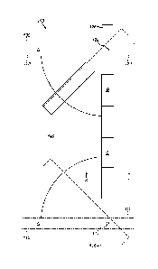
Figure 1 is a front view of a barrier showing the full range of movement from
the open
position to the closed position and finally to the locked position;
Figure 2 is a bottom view showing the underside of the barrier in the locked
position (the
dashed lines of the coupling show the closed position);
Figure 3 is a cross-sectional side view of the barrier showing the view
towards the
second support; and
Figure 4 is an enlarged view of Figure 3 showing the coupling and first
retaining means
arranged on the first arm.
Detailed Description of the Invention
Referring to Figure 1, a barrier 100 is shown. The barrier 100 comprises a
first arm 110
moveable about a first support 112 by means of rotation. A central shaft 114
supports the first
arm 110 and allows the first arm 110 to rotate. Although not shown, bearings
are provided on
the first support 112 to promote smooth rotation of the first arm 110. A
second arm 120 is also
shown. The second arm 120 is also rotatable about a corresponding second
support 122 and
CA 02988345 2017-12-05
WO 2015/185939 PCT/GB2015/051645
8
suitable bearings are provided. The barrier 100 further comprises a coupling
130 mounted on
the second arm 120 whilst in an open position A. The first 112 and second 122
supports are
spaced across an opening 140. The barrier 100 is moveably arranged between the
open
position A and closed position B. In the open position A, the arms 110,120 are
upwardly
facing and rest in a substantially vertical orientation. This is the limit of
rotation about the
central shaft 114. In the closed position B, the arms 110,120 are rotated in a
downwards
direction to be arranged in combination to traverse the opening 140. The range
of movement
is balanced by counterweights 116,126 arranged in each arm 110,112 in order to
allow the
rotation of the barrier 100 to be controlled and smooth and reduce any bending
moments
whilst generated in the closed B position. This helps to give an assured
quality to the rotation
of the arms 110,120 and helps to avoid acceleration of the arms 110,120 when
moving
towards or away from the closed position B. The barrier 100 is further
arranged in a locked
position C, whereby the coupling 130 is slidably coupled to the first 110 and
second 120 arms.
The coupling 130 acts like a sleeve. The coupling 130 is hollow and arranged
on the exterior
surface of the arms 110,120. When in the open position A, the coupling 130 is
attached to the
second arm 120. Accordingly, the counterweight 126 arranged on the second arm
120 is
designed to accommodate the additional weight of the coupling 130 carried by
the second arm
120 in order to maintain equal ease of lifting to the first arm 110.
Further referring to Figure 2, a first retaining means 150 is disposed on the
first arm 110.
The first retaining means 150 is shown as a protrusion which impedes movement
of the
coupling 130 whilst the barrier 100 is in the locked position C. The first
retaining means 150 is
shown on the underside of the first arm 110 so that when in the closed B and
locked C
positions, the first retaining means 150 is not exposed and is therefore
better protected from
damage. Furthermore, a second retaining means 160 is shown on the second arm
120, once
again on the underside, for similar reasons. A further benefit of locating the
first and second
retaining means 150,160 on the underside of the first and second arms 110,120
is that visual
inspection and repair can be easily established when the barrier 100 is in the
open position A.
This allows the retaining means 150,160 to be easily assessed at a
comfortable, high level, as
opposed to an awkward, low level.
The coupling 130 is shown to travel a distance S when sliding the coupling 130
to
operate the barrier 100 from the closed position B (as shown by the dashed
lines) to the
locked position C. Distance S may be at least 25% or at least 30 `)/0 of the
length of the arm
from the distal end to the support. In the locked position C, the coupling 100
abuts the first
retaining means 150 on the first arm 110 and partially covers both arms
110,120 in order to
bridge the gap G between the arms 110,120. The coupling 130 can be used to
partially lock
the barrier 100 by sliding the coupling 130 partly along the first arm 110 but
not up to the first
retaining means 150. However, the effectiveness of the barrier 100 to lock the
arms 110,120
CA 02988345 2017-12-05
WO 2015/185939 PCT/GB2015/051645
9
and prevent distortion of the barrier 100 on impact is reduced. When the
coupling 130 is
retracted, the coupling abuts the second retaining means 160 on the second arm
120. This
helps to provide positive feedback so that the user knows that the barrier 100
is safe to open.
The first and second supports 112,122 are provided on a first and second base
118,128
respectively. Several bolts 119 are shown that are used to secure the first
and second bases
118,128 to the ground. The first and second base 118,128 accommodates the
first and
second supports 112,122 in that the first and second supports 112,122 are
stable and secure.
Although not shown, the bolts 119 are suitably long to prevent lateral
movement of the first and
second base 118,128.
Further referring to Figure 3, the barrier 100 is shown in the open position
A. In this
upright position, the second arm 120 is shown to be substantially vertical and
the coupling 130
is prevented from sliding along the second arm 120 by the second retaining
means 160. The
coupling 130 is shown to fully cover the circumference of the second arm 120
whilst in the
open position A and helps to protect the integrity of the second arm 120. The
second arm 120
is locked in the open position A by a locking member 180. Two locking members
180 are
shown as pins that protrude across the second arm 120 and prevent rotation of
the second
arm 120. Although not shown, these locking members 180 are spring loaded so
that when the
second arm 120 moves past the locking members 180 and towards the open
position A, the
locking members 180 retract and then spring outwardly locking the second arm
120 in place.
The locking members 180 are manually depressed to allow the second arm 120 to
be lowered
towards the closed and locked positions B,C.
The second support 122 is shown to comprise two support members either side of
the
arm. This allows the central shaft 124 to be fully supported in order to carry
the load of the
second arm 120 and coupling 130. The two support members allow the load to be
distributed
towards the base 128 which is shown to be relatively wide compared to one
support member.
This helps to reduce the pressure on the ground in order to prevent localised
sinking or
cracking.
It is appreciated from the discussion of the second arm 120 and the
corresponding
features of the second arm 120 as shown in Figure 3 that similar technical
features and
variations can be equally applied to the first arm 110 and the corresponding
features of the first
arm 120.
Finally referring to Figure 4, an enlarged view of the cross-section through
the first arm
110 of the barrier 100 is shown. This view shows the coupling 130 abutting the
first retaining
means 150 in the locked position C. The coupling 130 is a hollow member that
wraps around
CA 02988345 2017-12-05
WO 2015/185939 PCT/GB2015/051645
the first and second arms 110,120 when in the locked position C. The coupling
130 and the
first arm 110 are substantially circular. The coupling 130 and the first arm
110 are produced
from an extrusion process and form an extruded plastic. The first arm 110 is
also shown as a
hollow member in order to allow the first arm 110 to have reduced weight so
that the
5
respective counterweight 126 can have reduced mass and thus save material and
cost. The
first retaining means 150 is shown to have at least the same thickness as the
coupling 130.
The industrial application of the invention will be readily appreciated from
the description
herein. In particular, the barrier is capable of being made and used in
industry, especially in
the designated loading bays or 'goods in' or 'goods out' areas of a
manufacturing site.
10 Although
preferred embodiment(s) of the present invention have been shown and
described, it will be appreciated by those skilled in the art that changes may
be made without
departing from the scope of the invention as defined in the claims.