Note: Descriptions are shown in the official language in which they were submitted.
SINGLE AXLE, SEMI-LEVERED LANDING GEAR WITH SHORTENING
MECHANISM
BACKGROUND
1. Field
The exemplary embodiments generally relate to aircraft landing gear
systems and aircraft incorporating those landing gear systems and in
particular to
landing gear assemblies having a shortened length for stowing the landing gear
after retraction while being able to provide the aircraft with increased
rotation on
takeoff.
2. Brief Description of Related Developments
An aircraft generally includes landing gear to facilitate takeoff, landing and
taxi. For takeoff and landing of the aircraft, a taller landing gear is
desired to
generate a greater angle of rotation (e.g., angle of attack) of the aircraft.
The
landing gear of some aircraft includes a multi-axle truck beam pivotally
coupled to
.. a shock strut at, for example, a distal or lower end of the shock strut to
achieve
taller takeoff heights; however, multi-axle landing gear increases weight and
complexity of the landing gear.
For single axle landing gear, additional ground clearance for rotation of the
aircraft during takeoff is achieved by increasing the height of landing gear.
However, in order to increase the takeoff height using a single axle landing
gear,
the increased length results in the landing gear being moved further outboard,
from the aircraft fuselage, along the wing to compensate for the increased
length
of the landing gear on stowage. Further, increasing the length of the single
axle
landing gear increases the static height of the aircraft resulting in the need
for
new sill waterlines, longer and higher exit slides, a landing gear actuation
mechanism redesign, the need for off wing exit slides, landing gear stowage
compartment redesign, etc.
CA 2988558 2017-12-11 Page 1
=
SUMMARY
The following is a non-exhaustive list of examples, which may or may not
be claimed, of the subject matter according to the present disclosure.
One example of the subject matter according to the present disclosure
relates to a semi-levered landing gear including a shock strut, having an
inner
cylinder and an outer cylinder, the shock strut configured for coupling to an
airframe of an aircraft, a truck lever having a truck lever first end and a
truck lever
second end longitudinally spaced from the truck lever first end, the truck
lever
being rotatably coupled to the shock strut about a truck pivot axis of
rotation that
is disposed between the truck lever first end and the truck lever second end,
a
tension link assembly having a tension link assembly first end, a tension link
assembly second end, and at least one tension link assembly rotation axis
disposed between the tension link assembly first end and the tension link
assembly second end, the tension link assembly first end being coupled to the
shock strut outer cylinder, and the tension link assembly second end being
coupled to the truck lever second end, and a positioning mechanism being
configured for coupling to one or more of the airframe and the shock strut and
being coupled to the tension link assembly proximate the tension link assembly
first end, wherein the tension link assembly is configured to rotate the truck
lever
about the truck pivot axis of rotation between a truck lever extended position
and
a truck lever stowed position.
Another example of the subject matter according to the present disclosure
relates to an aircraft including an airframe, and a semi-levered landing gear
including a shock strut coupled to the airframe, a truck lever having a truck
lever
first end and a truck lever second end longitudinally spaced from the truck
lever
first end, the truck lever being rotatably coupled to the shock strut about a
truck
pivot axis of rotation that is disposed between the truck lever first end and
the
truck lever second end, a tension link assembly having a tension link assembly
first end, a tension link assembly second end and at least one tension link
assembly rotation axis disposed between the tension link assembly first end
and
CA 2988558 2017-12-11 Page 2
the tension link assembly second end, the tension link assembly first end
coupled
to the shock strut, and the tension link assembly second end being coupled to
the
truck lever second end, a positioning mechanism coupled to one or more of the
airframe and the shock strut and being coupled to the tension link assembly
proximate the tension link assembly first end, wherein the tension link
assembly
is configured to rotate the truck lever about the truck pivot axis of rotation
between
a truck lever extended position and a truck lever stowed position.
Still another example of the subject matter according to the present
disclosure relates to a semi-levered landing gear including a shock strut
coupled
to an airframe of an aircraft about a trunnion axis of rotation, a retraction
mechanism coupled to the airframe, a truck lever having a truck lever first
end and
a truck lever second end longitudinally spaced from the truck lever first end,
the
truck lever being rotatably coupled to the shock strut about a truck pivot
axis of
rotation that is disposed between the truck lever first end and the truck
lever
second end, a tension link assembly having a tension link assembly first end,
a
tension link assembly second end and at least one tension link assembly
rotation
axis disposed between the tension link assembly first end and the tension link
assembly second end, the tension link assembly first end being coupled to the
shock strut, and the tension link assembly second end being coupled to the
truck
lever second end, and a positioning mechanism configured for coupling to one
or
more of the airframe and the shock strut and being coupled to the tension link
assembly proximate the tension link assembly first end, wherein rotation of
the
truck lever about the truck pivot axis of rotation between a truck lever
extended
position and a truck lever stowed position is mechanically slaved to rotation
of the
shock strut about the trunnion axis of rotation.
Still another example of the subject matter according to the present
disclosure relates to a semi-levered landing gear including: a shock strut
having
an inner cylinder and an outer cylinder, the shock strut configured for
coupling to
an airframe of an aircraft; a truck lever having a truck lever first end and a
truck
lever second end longitudinally spaced from the truck lever first end, the
truck
Page 3
Date Recue/Date Received 2021-06-03
lever being rotatably coupled to the shock strut about a truck pivot axis of
rotation that is disposed between the truck lever first end and the truck
lever
second end; a tension link assembly having a tension link assembly first end,
a
tension link assembly second end, and at least one tension link assembly
rotation axis disposed between the tension link assembly first end and the
tension link assembly second end, the tension link assembly first end being
coupled to the shock strut outer cylinder, and the tension link assembly
second
end being coupled to the truck lever second end, the tension link assembly
including: an over-center link having an over-center link first end and an
over-
center link second end longitudinally spaced from the over-center link first
end,
the over-center link first end defining the tension link assembly first end
and
being rotatably coupled to the shock strut about an over-center pivot axis;
and a
truck link having a truck link first end and a truck link second end
longitudinally
spaced from the truck link first end, the truck link first end being rotatably
coupled to the over-center link second end about the tension link assembly
rotation axis and the truck link second end defining the tension link assembly
second end and being rotatably coupled to the truck lever second end; and a
positioning mechanism configured for coupling to one or more of the airframe
and the shock strut and being coupled to the tension link assembly proximate
the
.. tension link assembly first end, wherein the tension link assembly is
configured
to rotate the truck lever about the truck pivot axis of rotation between a
truck
lever extended position and a truck lever stowed position.
Still another example of the subject matter according to the present
disclosure relates to an aircraft including: an airframe; and a semi-levered
.. landing gear including: a shock strut coupled to the airframe; a truck
lever having
a truck lever first end and a truck lever second end longitudinally spaced
from
the truck lever first end, the truck lever being rotatably coupled to the
shock strut
about a truck pivot axis of rotation that is disposed between the truck lever
first
end and the truck lever second end; a tension link assembly having a tension
link assembly first end, a tension link assembly second end and at least one
tension link assembly rotation axis disposed between the tension link assembly
first end and the tension link assembly second end, the tension link assembly
Page 3a
Date Recue/Date Received 2021-06-03
first end coupled to the shock strut, and the tension link assembly second end
being coupled to the truck lever second end, the tension link assembly
including:
an over-center link having an over-center link first end and an over-center
link
second end longitudinally spaced from the over-center link first end, the over-
center link first end defining the tension link assembly first end and being
rotatably coupled to the shock strut about an over-center pivot axis; and a
truck
link having a truck link first end and a truck link second end longitudinally
spaced
from the truck link first end, the truck link first end being rotatably
coupled to the
over-center link second end about the tension link assembly rotation axis and
the
truck link second end defining the tension link assembly second end and being
rotatably coupled to the truck lever second end; and a positioning mechanism
coupled to one or more of the airframe and the shock strut and being coupled
to
the tension link assembly proximate the tension link assembly first end,
wherein
the tension link assembly is configured to rotate the truck lever about the
truck
pivot axis of rotation between a truck lever extended position and a truck
lever
stowed position.
Still another example of the subject matter according to the present
disclosure relates to a semi-levered landing gear including: a shock strut
coupled
to an airframe of an aircraft about a trunnion axis of rotation; a retraction
mechanism coupled to the airframe; a truck lever having a truck lever first
end
and a truck lever second end longitudinally spaced from the truck lever first
end,
the truck lever being rotatably coupled to the shock strut about a truck pivot
axis
of rotation that is disposed between the truck lever first end and the truck
lever
second end; a tension link assembly having a tension link assembly first end,
a
tension link assembly second end and at least one tension link assembly
rotation
axis disposed between the tension link assembly first end and the tension link
assembly second end, the tension link assembly first end being coupled to the
shock strut, and the tension link assembly second end being coupled to the
truck
lever second end, the tension link assembly including: an over-center link
having
an over-center link first end and an over-center link second end
longitudinally
spaced from the over-center link first end, the over-center link first end
defining
the tension link assembly first end and being rotatably coupled to the shock
strut
about an over-center pivot axis; and a truck link having a truck link first
end and
Page 3b
Date Recue/Date Received 2021-06-03
a truck link second end longitudinally spaced from the truck link first end,
the
truck link first end being rotatably coupled to the over-center link second
end
about the tension link assembly rotation axis and the truck link second end
defining the tension link assembly second end and being rotatably coupled to
the
truck lever second end; and a positioning mechanism configured for coupling to
one or more of the airframe and the shock strut and being coupled to the
tension
link assembly proximate the tension link assembly first end, wherein rotation
of
the truck lever about the truck pivot axis of rotation between a truck lever
extended position and a truck lever stowed position is mechanically slaved to
lo rotation of the shock strut about the trunnion axis of rotation.
BRIEF DESCRIPTION OF THE DRAWINGS
Having thus described examples of the present disclosure in general terms,
reference will now be made to the accompanying drawings, which are not
necessarily drawn to scale, and wherein like reference characters designate
the
same or similar parts throughout the several views, and wherein:
Page 3c
Date Recue/Date Received 2021-06-03
=
Figs. 1A-1C are schematic illustrations of an aircraft and semi-levered
landing gear in accordance with one or more aspects of the present disclosure;
Fig. 2 is a schematic illustration of the semi-levered landing gear in
accordance with one or more aspects of the present disclosure;
Fig. 3 is a schematic illustration of a portion of the semi-levered landing
gear in accordance with one or more aspects of the present disclosure;
Fig. 4 is a schematic illustration of a portion of the semi-levered landing
gear in accordance with one or more aspects of the present disclosure;
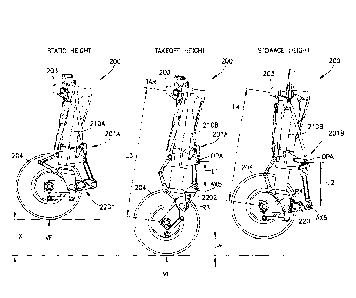
Fig. 5 is a schematic illustration of the semi-levered landing gear in a
static
height configuration, a takeoff height configuration and a stowage
configuration in
accordance with one or more aspects of the present disclosure;
Fig. 6 is a schematic illustration of a portion of the semi-levered landing
gear in accordance with one or more aspects of the present disclosure;
Fig. 7 is a schematic illustration of a portion of the semi-levered landing
gear in accordance with one or more aspects of the present disclosure;
Fig. 8 is a schematic illustration of the aircraft and the semi-levered
landing gear in accordance with one or more aspects of the present disclosure;
Fig. 9 is graph illustrating the ground contact vertical load of the semi-
levered landing gear versus the shock strut stroke of the semi-levered landing
zo gear in accordance with one or more aspects of the present disclosure;
and
Fig. 10 is a flowchart of a method for operating the semi-levered landing
gear shown in Figs. 1 to 8.
DETAILED DESCRIPTION
In order to achieve a greater angle of attack/rotation of the aircraft on
.. takeoff and/or landing, maintain current static ride heights and current
attachment
locations of a conventional landing gear, without having to redesign the
aircraft,
CA 2988558 2017-12-11 Page 4
the semi-levered landing gear described herein can increase height of the
aircraft
during takeoff and shorten a length of the landing gear in a stowing position
following takeoff for stowage in the current landing gear bay with little to
no
modification of the aircraft. In particular, the semi-levered landing gear
described
herein is both weight and cost efficient and is not overly complex, while
still
satisfying the static height, takeoff and/or landing height and stowage
requirements of the semi-levered landing gear.
The embodiments described herein provide a single axle, semi-levered
landing gear with a pivoting truck link and a landing gear length shortening
mechanism which generally has a simple configuration that can provide a low
static ride height of the aircraft, a tall takeoff height of the aircraft and
a shortened
landing gear length for stowage of the landing gear within the aircraft.
Illustrative, non-exhaustive examples, which may or may not be claimed,
of the subject matter according to the present disclosure are provided below.
Referring to Figs. 1A-1C and 2 an exemplary aircraft 100 and semi-levered
landing gear 200 with a shortening mechanism 201 is illustrated incorporating
aspects of the present disclosure.
In one aspect, while the semi-levered landing gear 200 described herein is
described with respect to a commercial passenger jet, referred to herein as
the
aircraft 100, in other aspects the aircraft may be any suitable aircraft
having a
fixed wing or variable sweep wing The semi-levered landing gear 200 may also
be used in landing gear having any suitable position on the aircraft 100, such
as
landing gear 200A, which may be a main landing gear, located towards a
longitudinal center of the aircraft 100, or in other aspects a nose landing
gear
200B located towards a longitudinal front of the aircraft 100. As will be
described
herein, the semi-levered landing gear 200 is configured to couple to one or
more
of the airframe 101 and the landing gear components (e.g., a landing gear
hydraulic actuator, landing gear extension/retraction mechanisms/linkages,
etc.)
of the aircraft 100 for providing the low static ride height, the tall take-
off height
and the shortened length for retraction of the semi-levered landing gear 200.
CA 2988558 2017-12-11 Page 5
Referring to Figs. 1B and 10, the semi-levered landing gear 200 is
illustrated in an extended and stowed position. A conventional single axle
landing gear 102 is also illustrated for comparison of the landing gear
attachment
locations relative to the airframe 101 of the aircraft 100. In one aspect, the
semi-
levered landing gear 200 provides the same static ride height A (e.g., the
distance from the ground to the lowest point on the aircraft 100 such as the
bottom of the fuselage 100F) as the conventional single axle landing gear 102
while being coupled to the airframe 101 further inboard, relative to the
centerline
CL of the fuselage 100F, by a predetermined distance B. As can be seen best in
Fig. 1B, upon retraction, the location of the landing gear wheel(s) 204 and
wheel
axis WA are located at a common location (e.g., within the wheel compartment
of
the aircraft 100 with little to no modification of the wheel bay) as
illustrated by the
retraction path 102A of the conventional single axle landing gear 102 and the
retraction path 200R of the semi-levered landing gear 200. As such, the semi-
levered landing gear 200 may be fit to an aircraft while maintaining the
existing
conventional landing gear bay of the aircraft, sill waterlines, etc., (i.e.,
the aircraft
100 does not have to be redesigned in order to accommodate the semi-levered
landing gear 200 and receive the increased takeoff and/or landing height and
aircraft rotation benefits of the semi-levered landing gear 200).
The semi-levered landing gear 200 in accordance with the aspects of the
present disclosure can provide for a landing gear system with less complexity
when compared to other, conventional landing gear shortening designs (such as
hydraulics that compress the shock strut upon retraction and stowage of the
landing gear), reduced weight compared to conventional landing gear shortening
designs, and/or contains less stored energy than conventional landing gear
shortening designs that perform the same or similar function (e.g., shortening
the
landing gear for retraction into the aircraft). For example, the semi-levered
landing gear 200 can be shortened for stowage within the aircraft without
compression of the shock strut 210 of the semi-levered landing gear 200.
Referring to Figs. 2 and 3, in one aspect and as noted above, the semi-
levered landing gear 200 is a single axle landing gear that includes a shock
strut
CA 2988558 2017-12-11 Page 6
' .
,
210, a truck lever 220, a tension link assembly 230, and a positioning
mechanism
240 (the tension link assembly 230 coupled to the positioning mechanism 240 is
also referred to hereinafter as a shortening mechanism 201). In one aspect,
the
semi-levered landing gear 200 includes at least one wheel 204. In one aspect,
the at least one wheel 204 is disposed on a common (e.g., single) axle of the
semi-levered landing gear. For example, in one aspect, the at least one wheel
204 includes two or more wheels disposed on the common axle. In one aspect,
the semi-levered landing gear 200 also includes a trunnion 203 coupled to the
shock strut 210 where the trunnion 203 is pivotally coupled to the airframe
101
(see Fig. 10) so that the semi-levered landing gear 200 pivots about a
trunnion
axis of rotation TAR between a landing gear stowed position and a landing gear
extended position. In one aspect, any suitable hydraulics and actuation
mechanisms/linkage may be coupled to semi-levered landing gear 200 for
actuation of the semi-levered landing gear 200. In one aspect, the landing
gear
actuation mechanism includes a retraction mechanism 202 to which the
shortening mechanism 201 is coupled as described herein. The retraction
mechanism 202 may be or include a walking beam.
In one aspect, the shock strut 210 includes an outer cylinder 211 and an
inner cylinder 212 that is movable relative to the outer cylinder 211. In one
aspect, the shock strut 210 may be gas over oil shock, while in other aspects
the
shock strut 210 may include any suitable dampening/rebound mechanism. In
one aspect, the inner cylinder 212 moves relative to the outer cylinder 211 to
compress and un-compress/extend the shock strut 210 under, e.g., the weight of
the aircraft 100. In one aspect, the shock strut 210 also includes a rotation
stop
213 that interacts with the shortening mechanism 201 as described herein. In
one
aspect, the rotation stop 213 is the outer cylinder 211 while in other aspects
the
rotation stop 213 may be coupled to the outer cylinder 211 in any suitable
manner. In one aspect, the rotation stop 213 is of unitary one piece
construction
with the outer cylinder 211 of the shock strut 210. In one aspect, as noted
above,
trunnion 203 is coupled to the outer cylinder 211 of the shock strut 210 so
that
the outer cylinder 211 is coupled to the airframe 101 of the aircraft 100. In
one
CA 2988558 2017-12-11 Page 7
aspect, the outer cylinder 211 of the shock strut 210 and the trunnion 203 are
formed as a unitary one piece member.
Still referring to Figs. 2 and 3, in one aspect, the truck lever 220 has a
truck lever first end 220a and a truck lever second end 220b longitudinally
spaced from the truck lever first end 220a. In one aspect, the truck lever 220
is a
rigid member, i.e., there are no articulated joints between the truck lever
first end
220a and the truck lever second end 220b. In one aspect, the truck lever 220
comprises a monolithic member. In one aspect, the truck lever 220 is pivotally
coupled to the inner cylinder 212 about a truck pivot axis of rotation TPA
disposed between the truck lever first end 220a and the truck lever second end
220b. In one aspect, as noted above, the truck lever 220 includes but one
wheel
axis WA that is disposed proximate the truck lever first end 220a between the
truck lever first end 220a and the truck pivot axis of rotation TPA. In one
aspect,
the shock strut 210 is substantially uncompressed with the truck lever 220 at
the
is truck lever extended position (see e.g. the takeoff height configuration
illustrated
in Fig. 5). In one aspect, the shock strut 210 is substantially uncompressed
with
the truck lever 220 at the truck lever stowed position (see e.g. the stowage
height
configuration illustrated in Fig. 5).
Still referring to Figs. 2 and 3, the shortening mechanism 201 includes a
tension link assembly 230 and a positioning mechanism 240. In one aspect, the
tension link assembly 230 includes a tension link assembly first end 230a, a
tension link assembly second end 230b, and at least one tension link assembly
rotation axis TLA disposed between the tension link assembly first end 230a
and
the tension link assembly second end 230b. In one aspect, the tension link
assembly 230 is coupled to both the truck lever 220 and the shock strut 210.
For
example, in one aspect, the tension link assembly first end 230a is rotatably
coupled to the outer cylinder 211 of the shock strut 210 in any suitable
manner
such as about an over-center pivot axis OPA. In one aspect, the tension link
assembly 230 is configured so that the truck lever 220 rotates about the truck
pivot axis of rotation TPA during compression and rebound of the shock strut
210
to provide for normal operation (e.g., the compression and rebound) of the
shock
CA 2988558 2017-12-11 Page 8
=
strut as well as being able to provide the increased takeoff height of the
aircraft
100. The tension link assembly 230 is also configured so that the truck lever
220
rotates about the truck pivot axis of rotation TPA to the stowed configuration
(see
Fig. 5) upon retraction and stowage of the semi-levered landing gear 200.
Referring to Figs. 2, 3, and 4, in one aspect, the tension link assembly 230
includes an over-center link 231 and a truck link 232. In one aspect, the
tension
link assembly 230 may include any suitable number of links. The over-center
link
231 includes an over-center link first end 231a and an over-center link second
end 231b longitudinally spaced from the over-center link first end 231a. In
one
lo aspect, the over-center link first end 231a defines the tension link
assembly first
end 230a and is rotatably coupled to the shock strut 210 about the over-center
pivot axis OPA in any suitable manner.
In one aspect, the truck link 232 includes a truck link first end 232a and a
truck link second end 232b longitudinally spaced from the truck link first end
15 232a. In one aspect, the truck link first end 232a is rotatably coupled
to the over-
center link second end 231b about the tension link assembly rotation axis TLA
so
that the truck link 232 and the over-center link 231 are configured to fold
and
unfold relative to each other about the tension link assembly rotation axis
TLA. In
one aspect, the truck link second end 232b defines the tension link assembly
20 second end 230b and is rotatably coupled to the truck lever second end
220b in
any suitable manner about axis AX5. The truck link second end 232b is
rotatably
coupled to the truck lever second end 220b such that the truck link 232 and
the
truck lever 220 fold and unfold relative to each other. The truck link 232
folding
and unfolding relative to the truck lever 220 rotates the truck lever 220
about the
25 truck pivot axis of rotation TPA between a truck lever extended position
and a
truck lever stowed position and to provide operation of the semi-levered
landing
gear 200 such as during compression and rebound of the shock strut 210. With
the truck link 232 unfolded relative to the truck lever 220, the tension link
assembly 230 is at a shortest length (as will be further described below)
rotating
30 the truck lever such that the at least one wheel 204 is further away from
the
trunnion axis of rotation TAR (i.e., during compression and rebound). With the
Page 9
CA 2988558 2017-12-11
,
truck link 232 folded relative to the truck lever 220, the tension link
assembly 230
is at a longest length (as will be further described below) rotating the truck
lever
220 such that the at least one wheel 204 is closer to the trunnion axis of
rotation
(i.e., stowed). The truck link 232 is configured to provide a tension load to
resist
a moment M that rotates the truck lever 220 about the truck pivot axis of
rotation
TPA created by a vertical force VF applied to the at least one wheel 204 by
the
ground, where the inner cylinder 212 provides an opposing a force VF1 to the
at
least one wheel 204 that opposes the vertical force VF.
Referring again to Fig. 2, in one aspect, the positioning mechanism 240
includes a number of links coupled to one or more of the shock strut 210, the
airframe 101 and the tension link assembly 230. The positioning mechanism 240
is provided to lock or unlock, as will be described further herein, the
tension link
assembly 230 where, when locked, the tension link assembly 230 resists the
moment M applied to the truck lever 220 about the truck pivot axis of rotation
TPA and where unlocked the truck lever 220 is positioned for stowage of the
semi-levered landing gear 200 in the landing gear bay of the aircraft 100. In
one
aspect, the number of links of the positioning mechanism 240 mechanically
slave
the orientation of the tension link assembly 230 to the extension and
retraction of
the semi-levered landing gear 200 from and to its stowed position within the
landing gear bay of the aircraft 100. In one aspect, the positioning mechanism
240 may not be mechanically slaved to the extension and retraction of the semi-
levered landing gear 200 from and to its stowed position within the landing
gear
bay of the aircraft 100. For example, here the positioning mechanism 240 may
include a linear actuator coupled to the outer cylinder 211 and the over-
center
link 231. In one aspect, the linear actuator is one of a hydraulic ram, a
pneumatic
ram, a ball screw actuator, or a solenoid. In one aspect, the linear actuator
is any
suitable type of actuator. In one aspect, the positioning mechanism 240 may
include a circular rotation actuator coupled to the outer cylinder 211 and the
over-
center link 231. In one aspect, the circular rotation actuator is one of a
stepper
motor or an electric motor. In one aspect, the circular rotation actuator is
any
suitable circular rotation actuator.
CA 2988558 2017-12-11 Page 10
Referring to Figs. 2, 3, and 4, in one aspect, the number of links of the
positioning mechanism 240 includes a connecting link 241, a first pivot link
242,
and a second pivot link 243. The connecting link 241 includes a connecting
link
first end 241a and a connecting link second end 241b. In one aspect, the
connecting link 241 is a rigid link (e.g., unarticulated so that there are no
articulated joints between the connecting link first and second ends 241a,
241b).
In one aspect, the connecting link first end 241a is coupled to the airframe
101 of
the aircraft 100 such as by rotatably coupling the connecting link first end
241a to
the retraction mechanism 202 so that the positioning of the truck lever 220 by
the
shortening mechanism 201 is mechanically slaved to the extension and
retraction
of the semi-levered landing gear 200 to and from the landing gear bay of the
aircraft 100. In one aspect, where the positioning of the truck lever 220 is
not
mechanically slaved, the connecting link first end 241a may be coupled to the
shock strut 210, such as to the outer cylinder 211 and be in the form of a
linear
actuator as described above. In one aspect, the connecting link second end
241b is coupled to the first pivot link 242 or the second pivot link 243 about
axis
AX4.
In one aspect, the first pivot link 242 includes a first end 242a and a
second end 242b longitudinally spaced from the first end 242a. The first end
242a of the first pivot link 242 is rotatably coupled to the shock strut 210,
such as
to the outer cylinder 211, in any suitable manner. In one aspect, the
connecting
link second end 241b is coupled to the second end 242b of the first pivot link
242
about the axis AX4.
In one aspect, the second pivot link 243 includes a first end 243a and a
second end 243b longitudinally spaced from the first end 243a. The first end
243a of the second pivot link 243 is rotatably coupled to the second end 242b
of
the first pivot link 242 about axis AX4. In one aspect, the connecting link
second
end 241b is coupled to the first end 243a of the second pivot link 243 about
axis
AX4. The first pivot link 242 and the second pivot link 243 fold and unfold
relative
to each other. The second end 243b of the second pivot link 243 is rotatably
coupled to the over-center link 231 proximate the over-center link second end
CA 2988558 2017-12-11 Page 11
231b so that folding and unfolding of the first pivot link 242 relative to the
second
pivot link 243, caused by connecting link 241, rotates the tension link
assembly
rotation axis TLA in direction R1, R2 about the over-center pivot axis OPA to
lock
and unlock the tension link assembly 230. In one aspect, the over-center link
231
.. includes one or more protrusions 231P that extend laterally away from a
centerline CLC of the over-center link 231 in a direction away from the shock
strut
210. The second end 243b of the second pivot link 243 is coupled to the one or
more protrusions 231P so that force applied by the second pivot link 243 to
the
over-center link 231 is applied off-center relative to the over-center pivot
axis
OPA so that a moment is produced about the over-center pivot axis OPA for
rotating the tension link assembly rotation axis TLA in direction R1, R2 about
the
over-center pivot axis OPA to lock and unlock the tension link assembly 230.
Referring now to Figs. 2-7, operation of the semi-levered landing gear 200
will now be described with respect to the aircraft 100. As can be seen best in
Fig.
5, as the weight of the aircraft 100 rests on the semi-levered landing gear
200,
the shock strut 210 is in a statically compressed state (noting that there
remains
travel within the shock strut to cushion the aircraft 100 for dynamic loading
during
taxi), hereafter referred to as the statically compressed shock strut 210A.
With
the statically compressed shock strut 210A in the statically compressed state
the
.. truck lever 220 is rotated about the truck pivot axis of rotation TPA so
that the
truck lever 220 is oriented in a static ride height configuration, hereinafter
the
static ride height truck lever 2201, to provide the aircraft with the static
ride height
A (Fig. 10, Block 1200). As described above, with the static ride height truck
lever
2201 at the static ride height configuration the aircraft 100 is provided with
a
.. static ride height A that is the same as the static ride height A of the
aircraft 100
when equipped with conventional single axle landing gear 102.
Here, with the semi-levered landing gear 200 in the static height and
takeoff height configurations, as illustrated in Fig. 5, the shortening
mechanism
201 is in an over center locked configuration 201A, e.g., the over-center link
.. second end 231b of the over-center link 231 is held against the rotation
stop 213
of the outer cylinder 211 in direction R1 by the tension forces acting on
truck link
CA 2988558 2017-12-11 Page 12
232 due to, for example, the vertical force VF acting upon the semi-levered
landing gear 200 (Fig. 10, Block 1205). In the over center locked
configuration
201A, the tension link assembly 230 is able to react the tension load to the
outer
cylinder 211 of the statically compressed shock strut 210A through the
rotation
stop 213 and the point at which the over-center link 231 couples to the outer
cylinder 211 of the statically compressed shock strut 210A. The tension load
tends to rotate the over-center link 231 about the over-center pivot axis OPA
in
the rotation direction R1 toward the rotation stop 213 on the outer cylinder
211 of
the statically compressed shock strut 210A because the line of action of the
tension load, through the truck link 232, in the over center locked
configuration
201A is between the rotation stop 213 and the over-center pivot axis OPA of
the
over-center link 231. As such, the tension load and resulting moments on the
tension link assembly 230 are isolated from the positioning mechanism 240.
As the aircraft 100 accelerates down the runway, the wings create lift. The
lift created reduces the portion of the weight of the aircraft 100 applied to
the
semi-levered landing gear 200. The reduction in weight applied to the semi-
levered landing gear 200 causes the shock strut 210 to extend or uncompress.
Movement of the inner cylinder 212 of the shock strut 210 relative to the
outer
cylinder 211 during extension causes the static ride height truck lever 2201
to
rotate to a takeoff height position, referred to as extended truck lever 2202,
as
seen best in Fig. 5 which can provide the aircraft 100 with additional height
X
relative to the static ride height A of the aircraft 100 (e.g. the static ride
height A
can be increased by height X at the takeoff height) (Fig. 10, Block 1210). The
additional height X, which is greater than the amount of extension provided by
the
shock strut 210, can provide for a predetermined angle of rotation 8 of the
aircraft
100 relative to the ground GR, as seen in Fig. 8, upon takeoff and provides
for a
predetermined angle of rotation a (e.g. angle of attack) of the aircraft 100
relative
to ground GR upon landing. Here the angles of rotation e, a can be increased
compared to takeoff and landing angles of rotation 8', a' of the aircraft 100
when
equipped with conventional single axle landing gear 102 where wheel travel is
limited only by an amount of travel of the shock strut and the distance Z
between
CA 2988558 2017-12-11 Page 13
the ground contact patch of the wheel(s) 204 and a tail skid pad 800 of the
aircraft remains the same for the aircraft 100.
The statically compressed shock strut 210A generally un-compresses until
the at least one wheel 204 is off the ground, i.e., the vertical force VF is
no longer
acting upon the semi-levered landing gear 200. As the statically compressed
shock strut 210A uncompresses, the shortening mechanism 201 remains in the
over center locked configuration 201A and, as described above, causes the
truck
lever 220 to pivot about the truck pivot axis of rotation TPA in the rotation
direction R3 to, at least, the truck lever extended position. The pivot of the
truck
lever 220 about the truck pivot axis of rotation TPA in the rotation direction
R3
provides a predetermined amount of ground contact vertical load so that the
aircraft 100 rotates to the rotation angle. In one aspect, the semi-levered
landing
gear 200 with an uncompressed shock strut 210B and the shortening mechanism
201 in the over center locked configuration 201A with an extended truck lever
2202, results in a first length L1 between the over-center link first end 231a
(e.g.
over-center pivot axis OPA) and the truck link second end 232b (e.g. axis AX5)
which provides a predetermined distance L3 between the but one wheel axle WA
and the trunnion 203 (e.g. the trunnion axis of rotation TAR where the semi-
levered landing gear 200 is coupled to the airframe 101) that can result in a
larger
amount of wheel travel during takeoff when compared to the conventional single
axle landing gear 102. The extended wheel travel provided by the distance L3
between the but one wheel axle WA and the trunnion axis of rotation TAR can
provide the aircraft 100 with an increased takeoff height (compared to the
takeoff
height of the conventional single axle landing gear 102 whose travel is
limited
solely by the extension of the shock strut) and/or an increased angle of
rotation 0
(e.g., angle of attack), again compared to conventional single axle landing
gear
102, illustrated in Fig. 1B.
After taking off, the semi-levered landing gear 200 is retracted into the
landing gear bay of the aircraft 100 (Fig. 10, Block 1215). As the weight of
the
aircraft 100 is no longer acting upon the semi-levered landing gear 200, the
shock strut 210B is uncompressed (e.g., without any vertical load VF acting on
CA 2988558 2017-12-11 Page 14
the semi-levered landing gear 200). The uncompressed shock strut 210B pivots
about the trunnion axis of rotation TAR of the trunnion 203 towards the shock
strut stowed position illustrated in Figs. 1B and 1C. In order to stow the
semi-
levered landing gear 200, as the uncompressed shock strut 210B pivots about
the trunnion axis of rotation TAR the semi-levered landing gear 200 is
shortened
to fit in the substantially unmodified landing gear bay (Fig. 10, Block 1220).
For
example, the tension link assembly 230 is moved from an over center locked
configuration 201A to an unlocked configuration 201B. In one aspect, the over-
center link 231 is rotated by the positioning mechanism 240 from the locked
position to the unlocked position, i.e., the over-center link 231 is rotated,
by for
example, the connecting link 241 away from the rotation stop 213 in rotation
direction R2 about the over-center pivot axis OPA until the distance between
the
tension link assembly first end 230a and the tension link assembly second end
230b is a second length L2. Generally, the first length L1 is shorter than the
second length L2. The second length L2 causes the distance between the but
one wheel axle WA and the trunnion axis of rotation TAR to be decreased from
about distance L3 to distance L4. The distance L4 between the but one wheel
axle WA and the trunnion axis of rotation TAR places the truck lever 220 in a
stowed configuration for the landing gear to be stowed into, for example, the
existing landing gear bay within the aircraft 100 with little to no
modification of the
landing gear bay.
As noted above, the rotation of the over-center link 231 from locked
position to unlocked position is controlled by the positioning mechanism 240.
In
order to change the orientation of the over-center link 231 from locked
position to
unlocked position, the positioning mechanism 240, for example, pushes or
actuates the truck link first end 232a in rotation direction R2. In one
aspect, as
described above, the positioning mechanism 240 is mechanically slaved to the
retraction of the semi-levered landing gear 200 into the landing gear bay of
the
aircraft 100 while in other aspects the positioning mechanism 240 is actuated
independent of the retraction of the semi-levered landing gear into the
landing
gear bay of the aircraft 100. As the truck link first end 232a and the over-
center
link second end 231b are coupled about the tension link assembly rotation axis
CA 2988558 2017-12-11 Page 15
TLA, the over-center link second end 231b is also pushed or actuated in
rotation
direction R2 about the over-center pivot axis OPA. As the truck link first end
232a and the over-center link second end 231b rotate in direction R2, the
truck
lever 220 is rotated about the truck pivot axis of rotation TPA in rotation
direction
R4 to the truck lever stowed position, as illustrated in Fig. 5, which
shortens the
semi-levered landing gear 200 a distance Y relative to the semi-levered
landing
gear 200 with a substantially uncompressed shock strut 210B and with the
shortening mechanism 201 in the over center locked configuration 201A with an
extended truck lever 2202. Shortening the semi-levered landing gear 200
through
rotation of the truck lever 220 about the truck pivot axis of rotation TPA in
rotation
direction R4 to the truck lever stowed position provides for positioning of
the
trunnion axis of rotation TAR closer to the centerline CL of the aircraft 100
compared to an aircraft having a conventional single axle shock strut 102 with
the
same uncompressed length at stowage as illustrated in Figs. 1B and 1C.
Upon aircraft 100 approach for landing, the semi-levered landing gear 200
is extended from the landing gear bay of the aircraft 100 (Fig. 10, Block
1225).
The uncompressed shock strut 210B pivots about the trunnion axis of rotation
TAR of the trunnion 203 towards the shock strut extended position. As the
uncompressed shock strut 210B pivots the about the trunnion axis of rotation
TAR, the truck lever 220 of the semi-levered landing gear 200 extends the
distance Y in a manner substantially opposite to that described above with
respect to the retraction of the semi-levered landing gear 200 to the stowed
configuration within the landing gear bay of the aircraft 100. For example,
the
positioning mechanism 240 pulls or actuates the truck link first end 232a in
rotation direction R1. As the truck link first end 232a and the over-center
link
second end 231b are coupled about the tension link assembly rotation axis TLA,
the over-center link second end 231b is also pulled or actuated in rotation
direction R1 about the over-center pivot axis OPA. As the truck link first end
232a and the over-center link second end 231b rotate in direction R1, the
truck
lever 220 is rotated about the truck pivot axis of rotation TPA in rotation
direction
R3 to the extended truck lever position, as illustrated in Figs. 2 and 5.
CA 2988558 2017-12-11 Page 16
Referring now to Fig. 9, a graph for the semi-levered landing gear 200 is
illustrated showing the ground contact vertical load (e.g. VF) versus the
shock strut
stroke. It is noted that the shock strut stroke in Fig. 9 is measured from the
extended configuration of the shock strut 210 so that as the shock strut is
compressed the ground contact vertical load can be increased. In order for the
aircraft to take off, there must be enough force translation through the
wheel(s)
204 into the aircraft 100 for the aircraft 100 to pivot about the wheel(s) 204
for
takeoff and landing. As the shock strut 210 of the semi-levered landing gear
200
extends or uncompresses during takeoff, the ground contact vertical load
decreases. However, as can be seen by the curve P in Fig. 9, there is
sufficient
ground contact vertical force translating through the wheels 204 with the
shock
strut 210 uncompressed and the truck lever 220 extended (e.g., the extended
load
region of the curve P) to get a reaction between the ground and the semi-
levered
landing gear 200 to create a moment for the aircraft 100 to pivot, noting that
as
the shock strut stroke increases the compression of the shock strut increases
(as
shown in Fig. 9).
In the figures, referred to above, solid lines, if any, connecting various
elements and/or components may represent mechanical, electrical, fluid,
optical,
electromagnetic, wireless and other couplings and/or combinations thereof. As
used herein, "coupled" means associated directly as well as indirectly. For
example, a member A may be directly associated with a member B, or may be
indirectly associated therewith, e.g., via another member C. It will be
understood
that not all relationships among the various disclosed elements are
necessarily
represented. Accordingly, couplings other than those depicted in the drawings
may also exist. Dashed lines, if any, connecting blocks designating the
various
elements and/or components represent couplings similar in function and purpose
to those represented by solid lines; however, couplings represented by the
dashed
lines may either be selectively provided or may relate to alternative examples
of
the present disclosure. Likewise, elements and/or components, if any,
represented with dashed lines, indicate alternative examples of the present
disclosure. One or more elements shown in solid and/or dashed lines may be
omitted from a particular example without departing from the scope of the
present
disclosure. Environmental elements, if any, are represented with dotted lines.
Page 17
Date Recue/Date Received 2021-06-03
Virtual (imaginary) elements may also be shown for clarity. Those skilled in
the
art will appreciate that some of the features illustrated in the figures, may
be
combined in various ways without the need to include other features described
in
the figures, other drawing figures, and/or the accompanying disclosure, even
though such combination or combinations are not explicitly illustrated herein.
Similarly, additional features not limited to the examples presented, may be
combined with some or all of the features shown and described herein.
In Fig. 10, referred to above, the blocks may represent operations and/or
portions thereof and lines connecting the various blocks do not imply any
particular
order or dependency of the operations or portions thereof. Blocks represented
by
dashed lines indicate alternative operations and/or portions thereof. Dashed
lines,
if any, connecting the various blocks represent alternative dependencies of
the
operations or portions thereof. It will be understood that not all
dependencies
among the various disclosed operations are necessarily represented. Fig. 10
and
the accompanying disclosure describing the operations of the method(s) set
forth
herein should not be interpreted as necessarily determining a sequence in
which
the operations are to be performed. Rather, although one illustrative order is
indicated, it is to be understood that the sequence of the operations may be
modified when appropriate. Accordingly, certain operations may be performed in
a different order or simultaneously. Additionally, those skilled in the art
will
appreciate that not all operations described need be performed.
In the foregoing description, numerous specific details are set forth to
provide a thorough understanding of the disclosed concepts, which may be
practiced without some or all of these particulars. In other instances,
details of
known devices and/or processes have been omitted to avoid unnecessarily
obscuring the disclosure. While some concepts will be described in conjunction
with specific examples, it will be understood that these examples are not
intended
to be limiting.
Unless otherwise indicated, the terms "first", "second", etc. are used herein
merely as labels, and are not intended to impose ordinal, positional, or
hierarchical
requirements on the items to which these terms refer. Moreover, reference to,
Page 18
Date Recue/Date Received 2021-06-03
e.g., a "second" item does not require or preclude the existence of, e.g., a
"first"
or lower-numbered item, and/or, e.g., a "third" or higher-numbered item.
Reference herein to "one example" means that one or more feature,
structure, or characteristic described in connection with the example is
included in
at least one implementation. The phrase "one example" in various places in the
specification may or may not be referring to the same example.
As used herein, a system, apparatus, structure, article, element,
component, or hardware "configured to" perform a specified function is indeed
capable of performing the specified function without any alteration, rather
than
merely having potential to perform the specified function after further
modification.
In other words, the system, apparatus, structure, article, element, component,
or
hardware "configured to" perform a specified function is specifically
selected,
created, implemented, utilized, programmed, and/or designed for the purpose of
performing the specified function. As used herein, "configured to" denotes
existing
characteristics of a system, apparatus, structure, article, element,
component, or
hardware which enable the system, apparatus, structure, article, element,
component, or hardware to perform the specified function without further
modification. For purposes of this disclosure, a system, apparatus, structure,
article, element, component, or hardware described as being "configured to"
perform a particular function may additionally or alternatively be described
as
being "adapted to" and/or as being "operative to" perform that function.
Different examples of the apparatus(es) and method(s) disclosed herein
include a variety of components, features, and functionalities. It should be
understood that the various examples of the apparatus(es) and method(s)
disclosed herein may include any of the components, features, and
functionalities
of any of the other examples of the apparatus(es) and method(s) disclosed
herein
in any combination, and all of such possibilities are intended to be within
the scope
of the present disclosure.
Many modifications of examples set forth herein will come to mind to one
skilled in the art to which the present disclosure pertains having the benefit
of the
teachings presented in the foregoing descriptions and the associated drawings.
Page 19
Date Recue/Date Received 2021-06-03
Therefore, it is to be understood that the present disclosure is not to be
limited to the specific examples illustrated and that modifications and other
examples are intended to be included within the scope of the appended claims.
Moreover, although the foregoing description and the associated drawings
describe examples of the present disclosure in the context of certain
illustrative
combinations of elements and/or functions, it should be appreciated that
different
combinations of elements and/or functions may be provided by alternative
implementations without departing from the scope of the appended claims.
Accordingly, parenthetical reference numerals in the appended claims, if any,
are
presented for illustrative purposes only and are not intended to limit the
scope of
the claimed subject matter to the specific examples provided in the present
disclosure.
Page 20
Date Recue/Date Received 2021-06-03