Note: Descriptions are shown in the official language in which they were submitted.
- 1 -
A Hose for Connection to a Gas Cylinder
The present invention relates to a hose for connection to a gas cylinder.
Gas cylinders are portable freestanding devices which are delivered to various
sites for the
supply of, for example, industrial and medical gases to locations where no
mains gas
supply is available. Because of the nature of these cylinders, they are often
supplied in
advance to the end user who may have little or no experience in fitting the
cylinders to the
gas consuming equipment.
In some cases, multiple gas hoses are connected to a gas manifold which
receives gas
supplies from more than one cylinder. If a hose has not been connected to one
port of the
manifold, this can provide a vent path for cylinders connected to other ports
of the manifold.
This is at best wasteful and at worst dangerous if there is an uncontrolled
leak of gas.
In the case of a single cylinder, the connectors are designed such that they
will not
dispense gas until the connection is properly made. However, it is still
useful to know that
the hose is correctly connected to ensure continuity of gas supply to the gas
consuming
equipment.
According to a first aspect of the present invention, there is provided a hose
according to
claim 1.
The motion sensor which detects movement of the first end and/or the nut
allows the
detection of an event associated with connecting and/or disconnecting the hose
providing
useful information on the state of connection of the hose to the cylinder.
The motion sensor may be an accelerometer. This may be set up to sense, for
example, a
change of angle of the first end of the hose. Sensing the change of angle is
characteristic
of disconnection of the hose from the cylinder resulting in an abrupt drop.
The subsequent
angle of the end indicates that the end has been reconnected. Alternatively or
additionally
the sensor may be configured to sense vibrations caused by rotation of the
nut. This
demonstrates that the nut has been unscrewed or screwed.
CA 2988750 2017-12-13
- 2 -
Alternatively or additionally the sensor may be a detectable tag provided on
the nut. The
detectable tag may, for example, be a hall sensor to detect a passing magnetic
field.
Alternatively it may be a light sensor to sense a passing pattern. In either
case, the sensor
may be on the nut with the component to be sensed being on the hose, or these
two
components may be arranged the other way around. The motion sensor is
configured to
detect the passing of the tag as the nut is rotated. This provides direct
sensing of the
rotation of the nut and therefore determines that the nut has been screwed or
unscrewed.
The tag may not need to be capable of detecting the direction of rotation. It
can be
assumed that if one set of signals indicating rotation is relatively quickly
followed by a
second set of signals, that the first represents unscrewing of the nut and the
second
represents screwing up of the nut. Alternatively, the tag may be configured to
sense the
direction of rotation. For example, if the tag is made up of two or more
elements
generating different electronic signals, the order of receipt of these signals
at the sensor
provides an indication of the direction of rotation.
The hose may be connected directly to the cylinder. Alternatively, the hose
may be
connected to the cylinder via a regulator. As a further option, the hose may
additionally or
alternatively be connected to the cylinder via a manifold to which a number of
other hoses
are connected. In this instance, preferably, the manifold has a plurality of
inlet ports via
one of which the hose is connected to the cylinder.
The invention also extends to a system comprising a hose according to the
first aspect of
the present invention together with a remote unit, the remote unit having a
receiver to
receive signals from the transmitter, the remote unit being programmed with at
least one
predetermined signal characteristic of a particular movement of the first end
of the hose
and/or nut and a controller to compare the received signal against the
predetermined signal
characteristic to detect a particular movement condition. In this case,
preferably, the
receiver is configured to receive signals from the transmitters of more than
one of the
hoses.
An example of the present invention will now be described with reference to
the
accompanying drawings in whichFig. 1 is a schematic cross-section through the
hose
connected to a cylinder and remote unit;
Fig. 2 is a schematic view of a first sensor configuration;
Figs. 3A to 3C are schematic views of a second sensor configuration;
CA 2988750 2017-12-13
- 3 -
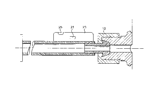
Fig. 4 is a schematic cross-section through a first end of the hose connected
to the nut 10
showing a further sensor configuration;
Figs. 4A and 4B are schematic views of the first end of the hose shown in Fig.
4 in different
orientations; and
Fig. 5 is a schematic view of the remote unit.
The cylinder 1 is a standard gas cylinder provided with a gas outlet 2 with a
screw threaded
connection 3. The invention is specifically designed to connect to standard
cylinders
without modification so that no further description of the cylinder will be
provided here. It
should be noted, however, that the invention could also be applied to a
cylinder with a
female screw thread.
The hose 5 is again a standard component with a flexible connection between
the cylinder
1 and a first end 6 and gas consuming equipment 7 at a second end 8.
The connector at the first end 6 is made up of two main components, namely an
insert 9
and a screw threaded nut 10. The insert 9 is inserted into the first end 6 of
the hose 5 and
has a number of ridges 11 to enhance the interference fit with the hose. A
crimp
connection ensures a gas tight seal between the hose 5 and insert 9. The end
of the insert
9 which protrudes from the tube 5 has a flange 13 which is sealed to the end
of the outlet 2
by metal to metal seal. The connection is secured by the nut 10 which has a
screw thread
15 which mates with the screw thread 3 on the outlet 2. The opposite end of
the nut 10
bears against the flange 13 to tighten the flange onto the outlet 2.
As described so far, this is a conventional way of attaching a hose to a
cylinder.
The improvement provided by the present invention is the provision of the
sensor 20. The
sensor may be attached to any part of the connection in the vicinity of the
first end 6. As
shown here, it is attached to the hose 5 but could also be attached to the
insert 9 or the nut
10.
As shown in Fig. 1, the nut 10 is provided with an electronically detectable
tag 21 such as a
magnet, RFID tag, distinctive marking or the like and the sensor 20 is
configured to detect
the passing of the tag 21 as the nut 10 is rotated. For example, Fig. 2
depicts the tag 21 as
CA 2988750 2017-12-13
- 4 -
a distinctive marking on the back of the nut which is detected by an optical
sensor 23 on
the nut 10 (shown schematically in Fig. 2) as the nut 10 rotates past the
markings. As
shown in Fig. 2, there are two distinctive markings spaced in close proximity
around the nut
so that rotation in one directed can be distinguished from rotation in the
opposite direction
depending on the order of sensing of the two tags 21.
An alternative is shown in Fig. 3A to 3C. In this case, the tag 21 is a magnet
and there are
a pair of hall sensors 24 providing the sensor 20. As the nut 10 is rotated in
the clockwise
direction shown in Fig. 3A, the sensor 24B will pass the magnet 21 shortly
before the
sensor 24A. Rotation in the opposite direction shown in Fig. 3B will cause the
opposite
effect in that the sensor 24A will pass the magnet 21 shortly before the
sensor 248 allowing
a controller to determine the direction of rotation.
A further alternative is shown in Fig. 4. In this case, the sensor 20 is
provided by an
accelerometer 31. In the normally connected configuration depicted in Fig. 4A,
the
accelerometer 31 is in a horizontal configuration. When the nut 10 is
disconnected,
because the hose 5 is unsupported, it will move to a generally vertical
configuration as
shown in Fig. 4B and the accelerometer is able to detect the movement to the
new
orientation.
As a further alternative, the accelerometer 31 shown in Fig. 4 may be replaced
by a
vibration sensor. In this case, as the nut 10 is vibrated, the effect of this
is transmitted to
the hose 5 and this is detected by the sensor. Alternatively the vibration
sensor may be
directly on the nut 10 so as to sense the motion of the nut 10 directly.
The information detected by the sensor 20 is transmitted via a transmitter 25
using any
known form of data transmission to a remote unit 40 comprising a receiver 41
and a
controller 42. The remote unit 40 may be a bespoke unit, or may be a smart
phone, tablet
or remote computer terminal. The receiver 41 receives the signal from the
sensor 20 and
the controller 42 compares the received signal with a database containing
information
regarding characteristic signals indicative of various conditions concerning
the attachment
and reattachment of the nut 10 as set out above. The controller 42 can
therefore
determine whether the nut 10 has been detached and/or reattached. This
information can
simply be logged for later diagnostic access. Alternatively or additionally it
can be used to
CA 2988750 2017-12-13
- 5 -
sound an alarm to a user or activate some form of safety procedure which will
not allow a
user to use the gas supply until the correct attachment of the nut 10 can be
verified.
CA 2988750 2017-12-13