Note: Descriptions are shown in the official language in which they were submitted.
CA 02988832 2017-12-08
WO 2017/013067
PCT/EP2016/067062
1
SILICONE CLIP
The present invention relates to a clip for a bracelet or a necklace, to
a bracelet or a necklace comprising such a clip and a method for assembly of
a clip.
Jewellery, such as necklaces and bracelets, often consists of a plu-
rality of freely movable ornamental components, e.g. beads or charms strung
on an elongated member, e.g. a chain, wire, or string. To prevent the freely
movable beads from grouping together at the bottom of the necklace or
bracelet or to group the freely movable beads in certain areas of the elon-
gated member, an ornamental component provided with a stopping mecha-
nism configured to grip the necklace or bracelet may be used. The ornamen-
tal component can be fixed or attached to the elongated member in one or
more positions along the elongated member and has such dimensions that
the freely movable beads are not able to move past the component. A variety
of such ornamental components have been suggested in the prior art.
An example of a prior art variation of such an ornamental component
is disclosed in Applicant's US 7,007,507 in which a band fixed to the elon-
gated member is configured to interact with an ornamental component to re-
movably attach said component to the band. The band may comprise external
threads interacting with external threads of the ornamental component. The
ornamental component may be a clip with two parts hinged to each other.
Since the band is fixed to the elongated member, it is not possible to freely
adjust the position of the ornamental component, which may be desirable in
some cases.
Resilient material such as silicone are commonly used for stopping
mechanisms. The resilient material will deform when it comes into contact
with a bracelet / necklace resulting in a spring force (attempting to restore
the
original shape of the stopping mechanism) that will releasably secure the or-
namental component to a selected position of the bracelet / necklace.
WO 2006/125155 discloses an example of such an ornamental com-
ponent, which uses a friction enhancing material positioned to abut the elon-
CA 02988832 2017-12-08
WO 2017/013067
PCT/EP2016/067062
2
gated member to achieve adjustable fixation of the ornamental component
along the strand. The friction enhancing material, such as silicone rubber,
covers all or a portion of the inside dimensions of an ornamental ring. The
material is bonded or moulded onto the interior surface of the ring.
It may, however, be difficult to secure the resilient material to the or-
namental component in a durable and easy manner.
Thus it remains a problem to provide a durable ornamental compo-
nent that is easier manufacture.
According to a first aspect, the invention relates to a
clip for a bracelet and/or a necklace, said clip in a closed state having
a through hole allowing said clip to wreathe an elongated member of a brace-
let and/or necklace, said through hole defining a through hole axis extending
in an axial direction, with a radial direction extending radially from the
axial
direction; said clip comprising:
= a first part and a second part, the first and second parts being con-
nected by a hinge; and
= a first resilient element arranged in said second part, the first
resilient
element comprising a first gripping surface for frictionally gripping a
surface of the elongated member;
wherein the second part comprises a cavity extending in the radial di-
rection, the first resilient element comprises a first resilient part arranged
in-
side said cavity and a second resilient part arranged outside said cavity and
extending in the radial direction from said cavity into said through hole,
wherein the cavity is configured to secure the first resilient element in said
second part.
Consequently, the first resilient element may be secured to the se-
cond part in an easy and secure manner. This further allows the first
resilient
element to be secured to the second part without or with limited use of adhe-
sives, thereby protecting the user from coming into contact with potential
harmful chemicals and increasing the aesthetic value of the ornamental com-
ponent.
CA 02988832 2017-12-08
WO 2017/013067
PCT/EP2016/067062
3
A clip may be any component that can be clipped on a bracelet and /
or necklace for ornamental purposes. A clip according to the first aspect of
the invention may be used to organize freely movable beads on a bracelet or
necklace, e.g. two clips may be arranged at desired position on an elongated
member of a bracelet or necklace, whereby they resiliently grip the elongated
member. Consequently, the bracelet or necklace is divided into three distinct
zones for freely movable beads. This may be used to prevent all the freely
movable beads from grouping together. The first part of the clip may comprise
a second resilient element comprising a second gripping surface for friction-
ally gripping a surface of the elongated member, whereby the first resilient
element and the second resilient element allows said clip to be releasably
secured at selected positions along the elongated member. Alternatively, the
first part of the clip may comprise a rigid second gripping surface, whereby
the first resilient element and the rigid second gripping surface allows said
clip
to be releasably secured at selected positions along the elongated member.
In the context of the present specification the term "wreathe" is to be
understood as meaning to cover, surround, or encircle.
In the context of the present specification the term "rigid" is to be un-
derstood as being substantially unable to bend or be forced out of shape dur-
ing normal use.
In the context of the present specification the term "resilient" is to be
understood as being able to recoil or spring back into shape after bending,
stretching, or being compressed.
The first resilient element is an element that that is deformable under
the influence of a particular force and capable of recoiling back into substan-
tially its original shape once the particular force is removed.
The first resilient element will be somewhat compressed in the radial
direction by the elongated member and vice versa will the first resilient ele-
ment exert a force in the radial direction on the elongated member, so that
the
elongated member is pushed towards the rigid second gripping surface, thus
creating tension between the rigid second surface and the elongated mem-
ber, so that the clip is releasably secured on said elongated member.
CA 02988832 2017-12-08
WO 2017/013067
PCT/EP2016/067062
4
The first resilient element may be made of a resilient material such
as a silicone material including a silicone rubber. Preferably the first
resilient
element is manufactured from a material comprising at least 50, more pre-
ferred at least 80, more preferred at least 95 percent of, most preferred es-
sentially consists of, a material or a combination of materials selected from
the group consisting of silicone, silicone rubber, natural rubber, synthetic
rub-
ber, PTFE, polyethylene, polypropylene, HDPE, polystyrene and nylon. The
first resilient element material may comprise additives and fillers, including
colouring agents.
In some embodiments, the first resilient element is being spaced apart
from the first part.
The first resilient element is spaced apart from the first part in a re-
laxed / uncompressed state and in a compressed state, when the clip
is arranged on the elongated member. In the context of the present
specification the term "spaced apart" is to be understood as being
separated, having spaces between, not being in direct contact.
The first resilient element may be secured to the second part by any means
such as by an adhesive or by griping means in the second part.
The clip may be forced to move along the elongated member, on
which it is positioned by exerting a force in the axial direction, preferably
using
a hand.
The first and second parts of the clip may provide the primary struc-
tural strength of the clip. The clip may be made of metal, glass, wood,
plastic,
ceramics or a combination thereof. The first and second parts of the clip may
be individually integrally moulded, i.e. made from a single mould.
The clip may have any outer shape such as round or rectangular.
Correspondingly, the through hole of the clip in an assembled state may have
any shape such as round or rectangular.
In some embodiments the cavity is shaped so as to grip the first resil-
ient part and secure the first resilient element in said second part.
During manufacture of the clip the first resilient part of the first resil-
ient element may thus be readily arranged in said cavity using the resilience
CA 02988832 2017-12-08
WO 2017/013067
PCT/EP2016/067062
of the material to compress it to fit through an opening of the cavity. When
inserted into the cavity the first resilient part may again expand to fit into
the
cavity and be secured therein.
The cavity may have a depth dimension in the radial direction that is
5 1/5 to 4/5 of a largest total extent of the second part in the radial
direction,
preferably 1/4 to 3/4, more preferred approximately 1/2. In case of a clip
with
a circular shape the largest total extent of the second part in the radial
direc-
tion corresponds to a diameter of the circle.
In some embodiments the first resilient part has a first outer surface
and the second resilient part has a second outer surface, the first outer sur-
face and the second outer surface extending at an angle with respect to each
other.
Consequently, the second resilient part may extend into the through
hole allowing the first gripping surface to grip the elongated member, when
the clip is arranged on said elongated member.
In some embodiments the second part comprises a shell having an
outer surface and an inner surface, the cavity comprises at least one side
wall
extending from the inner surface of the shell of the second part, the at least
one side wall being configured to grip the first resilient part and secure the
first resilient element in said second part.
In some embodiments the first resilient element defines a height ex-
tending in the radial direction and a width along a reference axis being per-
pendicular to the radial direction and the through hole axis, where the maxi-
mum width of the first resilient part is larger than the maximum width of the
second resilient part.
Hereby the width of the first resilient part and the shape of the at
least one side wall secures the first resilient element to the second part.
In some embodiments the second part comprises a shell having an
outer surface and an inner surface, the cavity comprises two side walls ex-
tending from the inner surface of the shell of the second part, the two side
walls being configured to grip the first resilient part and secure the first
resili-
ent element in said second part.
CA 02988832 2017-12-08
WO 2017/013067
PCT/EP2016/067062
6
The first resilient element may substantially fit in the cavity in the di-
rection of the through hole axis. The first resilient element may be slightly
compressed within the cavity in the direction of the through hole axis. Thus
any significant movement of the first resilient element inside the cavity in
the
direction of the through hole axis is prevented so that the first resilient
ele-
ment is held in the desired position.
In some embodiments an air filled cavity is formed between a bottom
of the first resilient element and a bottom of the cavity at least when the
first
resilient element is in an un-compressed state, thereby allowing the resilient
member to expand further into the cavity in response to a force exerted by an
elongated member of a bracelet and/or necklace on the first gripping surface.
This may reduce the stress induced on the first resilient element dur-
ing normal use. Furthermore, it may limit the expansion of the first resilient
element in a direction along the through hole axis, thereby both securing that
the first resilient element is kept within the protective first and second
parts of
the clip and prevent the first resilient element from being twisted out of the
cavity.
In some embodiments the first gripping surface is a smooth, even
surface.
In some embodiments the through hole comprises a first and a sec-
ond, opposite opening with respect to the through hole axis. The through hole
may have a constant width or may have a varying width (measured in planes
being perpendicular to the through hole axis. e.g. the through hole may be
wider at a central part than at the first and second openings of the through
hole.
In some embodiments the first resilient element has a third resilient
part, the third resilient part protruding from the first gripping surface, the
third
resilient part having a third gripping surface for gripping a surface of the
elon-
gated member, whereby the clip may be releasably secured to parts of the
elongated member having different widths.
In some embodiments the first resilient element has a fourth resilient
part, the fourth resilient part protruding from the first gripping surface,
the
CA 02988832 2017-12-08
WO 2017/013067 PCT/EP2016/067062
7
fourth resilient part having a fourth gripping surface for gripping a surface
of
the elongated member.
By providing a first resilient element having the third and fourth resili-
ent parts protruding from the first gripping surface, the clip may be
positioned
on parts of the elongated member having different widths, whilst still
releasably securing the clip to the elongated member, i.e. the first gripping
surface may enable the clip to grip around parts of the elongated having an
extended width such as a band on the elongated member (as long as the
length of the band is not larger than the distance between the third resilient
part and the fourth resilient part), and the third and fourth gripping surface
may grip around the remaining parts of the elongated member.
In some embodiments the first resilient element positioned in the
second part, has a width along the through hole axis of less than 95 %, 90 %,
80 %, 70 %, 60 % or 50 % of the width of the second part along the through
hole axis.
In some embodiments, the first resilient element is arranged with a
distance to the first and second opening of the through hole of the clip.
In some embodiments, the first and / or second opening of the
through hole of the clip have a shape and size substantially matching the
shape and size of the part of the elongated member of the bracelet / necklace
designated for receiving the clip, whereby at least a part of the surfaces sur-
rounding the openings may function as blocking surfaces for preventing the
clip from being moved over a part of the elongated member having an ex-
tended width.
In some embodiments the first part comprises a closing element for
releasably securing the first and second part to each other in said closed
state of the clip.
In some embodiments the closing element is arranged inside the clip,
so that the clip encloses the closing element in said closed state of the
clip.
In some embodiments the closing element is a leaf spring arranged
inside the first part, a part of the leaf spring extending out of the first
part and
in a closed state of the clip extending into the second part.
CA 02988832 2017-12-08
WO 2017/013067
PCT/EP2016/067062
8
Consequently, a clip is provided that is exempt from having an exter-
nal closing mechanism obstructing the aesthetic appearance of the clip, thus
allowing a more freely design of the exterior surface of the clip.
In some embodiments the second part comprises a closing cavity for
receiving the part of the leaf spring extending out of the first part and in a
closed state of the clip extending into the second part.
In some embodiments the closing cavity comprises a closing protru-
sion, the closing cavity providing a releasable snap-lock with the part of the
spring extending from the first part in a closed state of the clip.
In some embodiments the clip has a length along the through hole
axis between lmm and 4 cm, between 2mm and 2cm, or between 2mm and 1
cm.
In some embodiments, said clip further comprises a second resilient
element arranged in said first part, the second resilient element comprising a
second gripping surface for frictionally gripping a surface of the elongated
member, wherein the first resilient element and the second resilient element
allows said clip to be releasably secured at selected positions along the elon-
gated member.
The second resilient element may be made of a material identical to
or similar to the material of the first resilient element.
In some embodiments, the first part comprises a cavity extending in
the radial direction, the second resilient element comprises a first resilient
part
arranged inside said cavity and a second resilient part arranged outside said
cavity and extending in the radial direction from said cavity, wherein the
cavity
is configured to secure the second resilient element in said first part.
In some embodiments the cavity is shaped so as to grip the first resil-
ient part and secure the second resilient element in said first part.
During manufacture of the clip the first resilient part of the second re-
silient element may thus be readily arranged in said cavity using the
resilience
of the material to compress it to fit through an opening of the cavity. When
inserted into the cavity the second resilient part may again expand to fit
into
the cavity and be secured therein.
CA 02988832 2017-12-08
WO 2017/013067
PCT/EP2016/067062
9
The cavity may have a depth dimension in the radial direction that is
1/5 to 4/5 of a largest total extent of the second part in the radial
direction,
preferably 1/4 to 3/4, more preferred approximately 1/2. In case of a clip
with
a circular shape the largest total extent of the second part in the radial
direc-
tion corresponds to a diameter of the circle.
The second resilient element may substantially fit in the cavity of the
first part in the direction of the through hole axis. The first resilient
element
may be slightly compressed within the cavity in the direction of the through
hole axis. Thus any significant movement of the first resilient element inside
the cavity in the direction of the through hole axis is prevented so that the
first
resilient element is held in the desired position.
In some embodiments an air filled cavity is formed between a bottom
of the second resilient element and a bottom of the cavity at least when the
second resilient element is in an un-compressed state, thereby allowing the
second resilient member to expand further into the cavity in response to a
force exerted by an elongated member of a bracelet and/or necklace on the
second gripping surface.
This may reduce the stress induced on the second resilient element
during normal use.
In some embodiments, the first part comprises a closing element for
releasably securing the first and the second part to each other in said closed
state of the clip, wherein the second gripping element is arranged on top of
the closing element and at least partly secures the closing element to the
first
part.
In some embodiments, the width along the through hole axis of the
first part of the second resilient element is larger than the width along the
through hole axis of the second part of the second resilient element.
In some embodiments, the first part of the clip comprises two flanges
extending along the through hole axis and being configured to grip the first
part of the second resilient element and secure the second resilient element
in said first part of the clip.
Consequently, the second resilient element may effectively be se-
CA 02988832 2017-12-08
WO 2017/013067
PCT/EP2016/067062
cured to the first part of clip, while still providing room for arranging a
closing
element in the first part of the clip.
In some embodiments, the second gripping surface is a smooth,
even surface.
5 In some
embodiments, the second resilient element has a third resili-
ent part, the third resilient part protruding from the second gripping
surface,
the third resilient part having a fifth gripping surface for gripping a
surface of
the elongated member, whereby the clip may be releasably secured to parts
of the elongated member having different widths.
10 In some
embodiments, the second resilient element has a fourth re-
silient part, the fourth resilient part protruding from the second gripping
sur-
face, the fourth resilient part having a sixth gripping surface for gripping a
sur-
face of the elongated member.
In some embodiments, the first part comprises a rigid second grip-
ping surface for gripping a surface of the elongated member, and the resilient
element and the rigid second gripping surface allows said clip to be releas-
ably secured at selected positions along the elongated member.
The rigid second gripping surface is a surface being substantially un-
able to bend or be forced out of shape during normal use. The rigid second
gripping surface may be made of a rigid material such as silver or steel. The
first part may have more than one rigid gripping surface e.g. the first part
may
have one rigid griping surface at the first opening of the through hole and
one
rigid gripping surface at the second opening of the through hole.
In some embodiments the rigid, second gripping surface of the first
part has a shape that is substantially equal to an outer shape of the
elongated
member of the bracelet / necklace.
In some embodiments the rigid, second gripping surface is concave
e.g. it has a semi-circular shape.
Hereby the second gripping surface may fit snugly around the elon-
gated member with a substantially circular surface, providing a larger area of
contact.
According to a second aspect, the invention relates to a bracelet or a
CA 02988832 2017-12-08
WO 2017/013067
PCT/EP2016/067062
11
necklace comprising:
= an elongated member; and
= a clip as disclosed in relation to the first aspect of the invention
config-
ured to be releasably secured at selected positions along at least a
part of the elongated member.
The elongated member may be any elongated member suitable for
jewelry such as a metal chain, leather string, a fabric string, or any other
type
of chain.
In some embodiments, the bracelet or necklace further comprises at
least one freely moveable ornamental component strung on said elongated
member.
In some embodiments, the bracelet or necklace further comprises a
plurality of freely moveable ornamental components strung on said elongated
member.
In some embodiments the bracelet or necklace further comprises a
second clip as disclosed in relation to the first aspect of the invention ar-
ranged on said elongated member, wherein the second clip is configured so
that the first gripping surface and the second gripping surface resiliently
grips
the elongated member to allow said second clip to be releasably secured at
selected positions along the elongated member until a particular force is act-
ing on said second clip, whereby the second clip can be moved along the
elongated member.
In some embodiments the bracelet or necklace further comprises a
band fixed to the elongated member; the band having an extended width
compared with the width of remaining parts of the elongated member,
wherein the clip is configured so that the second gripping surface and the
first
gripping surface grips the band to allow said clip to be releasably attached
to
said band.
The band may be a band on bracelet as disclosed in US 7,007,507.
The bracelet may comprise at least two bands.
According to a third aspect, the invention relates to a method for as-
sembly of a clip, said clip in a closed state having a through hole allowing
said
CA 02988832 2017-12-08
WO 2017/013067 PCT/EP2016/067062
12
clip to wreathe an elongated member of a bracelet and/or necklace, said
through hole defining a through hole axis extending in an axial direction,
with
a radial direction extending radially from the axial direction, comprising the
steps of:
= providing a
first part and a second part of the clip, the first and second
parts being connectable by a hinge, wherein the second part compris-
es a cavity extending in the radial direction;
= providing a first resilient element comprising a first gripping surface
for
frictionally gripping a surface of the elongated member, a first resilient
part and a second resilient part; and
= inserting the first resilient element in the cavity of said second part
so
that the first resilient part is arranged inside said cavity and the second
resilient part is arranged outside said cavity and extends in the radial
direction from said cavity into said through hole.
Consequently, an efficient method of assembling a clip is provided.
In some embodiments the clip is a clip as disclosed in relation to the
first aspect of the invention.
The different aspects of the present invention can be implemented in
different ways including as a clip, bracelets or necklaces comprising a clip,
and methods of assembling a clip described above and in the following, each
yielding one or more of the benefits and advantages described in connection
with at least one of the aspects described above, and each having one or
more preferred embodiments corresponding to the preferred embodiments
described in connection with at least one of the aspects described above and
/ or disclosed in the dependant claims.
Furthermore, it will be appreciated that embodiments described in
connection with one of the aspects described herein may equally be applied
to the other aspects.
The above and / or additional objects, features and advantages of
the present invention will be further elucidated by the following illustrative
and
non-limiting detailed description of embodiments of the present invention,
with
CA 02988832 2017-12-08
WO 2017/013067
PCT/EP2016/067062
13
reference to the appended drawings, wherein:
Figs. 1A-C show a clip according to a first embodiment of the present
invention.
Figs. 2A-C show a first resilient element for a clip according to the
first embodiment of the present invention.
Fig. 3 shows an exploded view of a clip according to the first embod-
iment of the present invention.
Fig.4 shows a cross-section of a clip according to the first embodi-
ment of the present invention.
Fig. 5 shows a first part of a clip according to an embodiment of the
invention.
Fig. 6 shows a first part of a clip according to an embodiment of the
invention.
Figs. 7A-C show a clip according to a second embodiment of the
present invention.
Figs. 8A-E show a first resilient element for a clip according to the
second embodiment of the present invention.
Fig. 9 shows an exploded view of a clip according to the second em-
bodiment of the present invention.
Fig.10 shows a cross-section of a clip according to the second em-
bodiment of the present invention.
Fig. 11 shows schematically a bracelet / necklace comprising one or
more clips according an embodiment of the invention.
Figs. 12A-B show a clip according to a third embodiment of the pre-
sent invention.
Figs. 13A-C show a second resilient element for a clip according to
the third embodiment of the present invention.
Fig. 14A shows an exploded view of a second part of a clip according
to the third embodiment of the present invention.
Fig. 14B shows an exploded view of a first part of a clip according to
the third embodiment of the present invention.
Fig. 14B shows a view of a second part of a clip according to the
CA 02988832 2017-12-08
WO 2017/013067
PCT/EP2016/067062
14
third embodiment of the present invention.
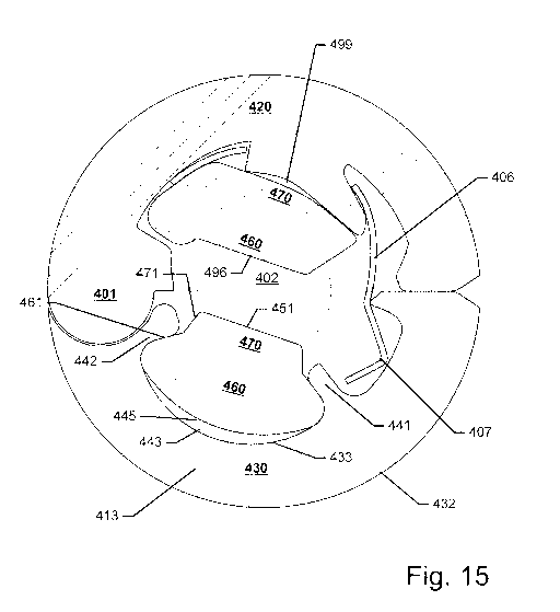
Fig.15 shows a cross-section of a clip according to the third embodi-
ment of the present invention.
In the following description, reference is made to the accompanying
figures, which show by way of illustration how the invention may be practiced.
Figs. 1-5 show a clip 100 according to a first embodiment of the pre-
sent invention. Fig. 1A-C show the clip 100 assembled, where Fig. 1A shows
a side view, Fig. 1B shows a perspective view, and Fig. 10 shows a top view.
Figs. 2A-C show a first resilient element 150 of the clip 100, where
Fig. 2A shows a bottom view, Fig. 2B shows a side view, and Fig. 20 shows a
perspective view.
Fig. 3 shows an exploded view of the clip 100.
Fig. 4 shows a cross-section of the clip along the line A shown in Fig.
1C.Fig. 5A-B show perspective views of a first part of the clip 120, where
Fig.
5A shows the first part 120 with a closing element 106 inserted, and Fig. 5B
shows the first part 120 without the closing element. Fig. 5C shows the clos-
ing element.
In the following reference will be made to Figs. 1-5.
The clip 100 is a clip for a bracelet and/or a necklace. The clip in a
closed state (as shown in Figs. 1 and 4) have a through hole 102 allowing the
clip 100 to wreathe an elongated member (such as a chain) of a bracelet
and/or necklace. The through hole 102 defining a through hole axis 103 ex-
tending in an axial direction, with a radial direction 104 extending radially
from
the axial direction. The clip 100 comprises a first part 120 and a second part
130, the first and second parts 120 130 being connected by a hinge 101. The
clip 100 further comprise a first resilient element 150 arranged in the second
part 130. The first resilient element 150 comprises a first gripping surface
151
for frictionally gripping a surface of the elongated member of a bracelet /
necklace. The first resilient element 150 is spaced apart from the first part
120
i.e. the first resilient element 150 does not touch the first part 120. The
first
part 120 comprises two rigid gripping surfaces 121 122 for gripping a surface
CA 02988832 2017-12-08
WO 2017/013067
PCT/EP2016/067062
of the elongated member. In this embodiment two rigid gripping surfaces
121 122 are two ridges arranged at the first and second opening of the
through hole 102 respectively. Fig. 6 shows an alternative design of the first
element according to an embodiment of the present invention, where the first
5 part 120 only is provided with a single rigid gripping surface 121.
The first resilient element 150 and the rigid gripping surfaces 121 122
allows the clip to be releasably secured at selected positions along the elon-
gated member i.e. the first resilient element 150 and the rigid gripping sur-
faces 121 together grips the elongated member and secures the clip to the
10 elongated member.
The clip may be forced to move along the elongated member, on
which it is positioned by exerting a force in the axial direction, preferably
using
a hand.
In this embodiment the through hole is circular and the clip 100 have
15 a cylindrical shape.
In this embodiment the two gripping surface 121 122 have a concave
shape (in a plane being perpendicular to the through hole axis103).
The first gripping surface 151 is a smooth even surface.
The through 102 hole may have a varying width (measured in planes
being perpendicular to the through hole axis 103, i.e. the through hole is
wider at a central part than at the first and second openings of the through
hole 103.
The second part 130 comprises a cavity 140 extending in the radial
direction 104, the first resilient element 150 comprises a first resilient
part 160
arranged inside the cavity 140 and a second resilient part 170 arranged out-
side the cavity 140 and extending in the radial direction 104 from the cavity
140. The cavity 140 being configured to secure the first resilient element 150
in the second part 130.
Consequently, the first resilient element may be secured to the se-
cond part in an easy and secure manner. This further allows the first
resilient
element to be secured to the second part without the use of an adhesive,
thereby protecting the user from coming into contact with potential harmful
CA 02988832 2017-12-08
WO 2017/013067
PCT/EP2016/067062
16
chemicals and increasing the aesthetic value of the ornamental component.
The cavity 140 is shaped so as to grip the first resilient part 160 and
secure the first resilient element 150 in the second part 130.
The first resilient part 160 has a first outer surface 161 and the se-
cond resilient part 170 has a second outer surface 171, the first outer
surface
161 and the second outer surface 171 extending at an angle with respect to
each other.
The second part comprises a shell 131 having an outer surface 132
and an inner surface 133, the cavity 140 comprises a first side wall 141 and a
second side wall 142 extending from the inner surface of the shell 133 of the
second part 130, the first and second side wall 141 142 being configured to
grip the first resilient part 160 and secure the first resilient element 150
in the
second part 130 of the clip 100.
The first resilient element 150 has a height 152 extending in the radi-
al direction and a width 172 162 along a reference axis being perpendicular to
the radial direction and the through hole axis 103, where the maximum width
162 of the first resilient part 160 is larger than the maximum width 172 of
the
second resilient part 170.
Thus the width of the first resilient part 16 and the shape / orientation
of the first and second side walls 141 142 secures the first resilient element
150 to the second part 130.
An air filled cavity 145 is formed between a bottom of the first resili-
ent element 150 and a bottom of the cavity 140 at least when the first
resilient
element is in an un-compressed state, thereby allowing the resilient member
150 to expand further into the cavity 190 in response to a force exerted by an
elongated member of a bracelet and/or necklace on the first gripping surface
451.
This may reduce the stress induced on the first resilient element 150
during normal use. Furthermore, it may limit the expansion of the first
resilient
element 150 in a direction along the through hole axis 103, thereby both se-
curing that the first resilient element 150 is kept within the protective
first and
second parts 120 130 of the clip 100 and prevent the first resilient element
CA 02988832 2017-12-08
WO 2017/013067
PCT/EP2016/067062
17
150 from being twisted out of the cavity 140. The first part 120 comprises a
closing element 106 for releasably securing the first and second part to each
other in the closed state of the clip 100.
The closing element 106 is arranged inside the clip 100, so that the
clip encloses the closing element in said closed state of the clip.
The closing element 106 is a leaf spring arranged inside the first part
120, a part of the leaf spring extending out of the first part 120 and in a
closed
state of the clip extending into the second part 130.
The first part comprises a protruding member 108 for securing the
closing element 106 to the first part 120, and the closing element 106 com-
prises an opening 109 for receiving the protruding member 108.
Figs. 7-10 show a clip 200 according to a second embodiment of the
present invention. Fig. 7A-C show the clip 200 assembled, where Fig. 7A
shows a side view, Fig. 7B shows a perspective view, and Fig. 70 shows a
top view.
Figs. 8A-E show a first resilient element 250 of the clip 200, where
Fig. 8A shows a top view, Fig. 8B shows a side view, and Fig. 8C-D show
perspective views, and Fig. 8e shows a front view.
Fig. 9 shows an exploded view of the clip 200.
Fig. 10 shows a cross-section of the clip 200 along the line B shown
in Fig. 70.
In the following reference will be made to Figs. 7-10.
The clip 200 is a clip for a bracelet and/or a necklace. The clip in a
closed state (as shown in Figs. 7 and 10) have a through hole 202 allowing
the clip 200 to wreathe an elongated member (such as a chain) of a bracelet
and/or necklace. The through hole 202 defining a through hole axis 203 ex-
tending in an axial direction, with a radial direction extending radially from
the
axial direction. The clip 200 comprises a first part 220 and a second part
230,
the first and second parts 220 230 being connected by a hinge 201. The clip
200 further comprise a first resilient element 250 arranged in the second part
230. The first resilient element 250 comprises a first gripping surface 251
for
frictionally gripping a surface of the elongated member of a bracelet / neck-
CA 02988832 2017-12-08
WO 2017/013067
PCT/EP2016/067062
18
lace. The first resilient element 250 is spaced apart from the first part 220
i.e.
the first resilient element 250 does not touch first part 220. The first part
220
comprises two rigid gripping surfaces 221 222 for gripping a surface of the
elongated member. In this embodiment two rigid gripping surfaces 221 222
are two ridges arranged at the first and second opening of the through hole
202 respectively. The clip 200 according to the second embodiment is gener-
ally similar to the clip 100 according to the first embodiment (disclosed in
rela-
tion to Figs. 1-5). There are however two main differences: the outer shape of
the clip 200 (being spherical) and the design of the first resilient element
250.
In this embodiment the first resilient element 250 has a third resilient
part 280, the third resilient part 280 protruding from the first gripping
surface
251, the third resilient part 280 having a third gripping surface 281 for
gripping
a surface of the elongated member. The first resilient element 250 has a
fourth resilient part 290, the fourth resilient part 290 protruding from the
grip-
ping surface 251, the fourth resilient part 290 having a fourth gripping
surface
282 for gripping a surface of the elongated member. By providing a first
resili-
ent element 250 having the third and fourth resilient parts 280 290 protruding
from the first gripping surface 251, the clip 200 may be positioned on parts
of
the elongated member having different widths i.e. the first gripping surface
251 may enable the clip 200 to grip around parts of the elongated member
having an extended width such as a band on the elongated member (as long
as the length of the band is not larger than the distance 299 between the
third
resilient part 280 and the fourth resilient part 290), and the third and
fourth
gripping surface 281 282 may grip around the remaining parts of the elongat-
ed member. In this embodiment, the clip 200 comprises only one resilient el-
ement, i.e. the first resilient element. However, in other embodiments the
clip
200 may comprise a second resilient element arranged in the first part 220 of
the clip, where the second resilient element comprises a second gripping sur-
face, and wherein the second resilient element has a third and fourth
resilient
part protruding from the second gripping surface, the third resilient part
having
a fifth gripping surface and the fourth resilient part having a sixth gripping
sur-
face, i.e. the second resilient element may have gripping surfaces corre-
CA 02988832 2017-12-08
WO 2017/013067
PCT/EP2016/067062
19
sponding to the gripping surfaces 251 281 282 of the first resilient element.
Fig. 11 shows schematically a bracelet / necklace 300 comprising an
elongated member 301 and one or more clips 304-307 according to an em-
bodiment of the present invention. The elongated member 301 comprises two
bands 302 303 having an extended width compared with the width of the re-
maining parts of the elongated member 301. The clips 304-307 are only
shown schematically. The clip disclosed in relation to Figs. 1-5 may be se-
cured to the elongated member only at the bands 302 303 or only at the re-
maining parts of the elongated member (unless the width of the bands only is
slightly extended). Preferably, the clip disclosed in relation to Figs. 1-5 is
con-
figured to be secured to the remaining parts of the elongated member. How-
ever, the clip disclosed in relation to Figs. 7-10 may be secured to the elon-
gated member both at the bands 302 303 and at the remaining parts of the
elongated member as a result of the three gripping surfaces 251 281 282.
Figs. 12-15 show a clip 400 according to a third embodiment of the
present invention. Fig. 12A-b show the clip 400 assembled, where Fig. 12A
shows a side view and Fig. 12B shows a top view.
Figs. 13A-C show a second resilient element 495 of the clip 400,
where Fig. 13A shows a perspective view, Fig. 13B shows a top view, and
Fig. 130 shows a side view.
Fig. 14A shows an exploded view of a second part 430 of the clip
400, Fig. 14B shows an exploded view of a first part 420 of the clip 400, and
Fig. 140 shows a perspective view of the second part 430 of the clip 400.
Fig. 15 shows a cross-section of the clip 400 along the line A shown
in Fig. 12B.
In the following reference will be made to Figs. 12-15.
The clip 400 is a clip for a bracelet and/or a necklace. The clip in a
closed state (as shown in Figs. 12 and 15) have a through hole 402 allowing
the clip 400 to wreathe an elongated member (such as a chain) of a bracelet
and/or necklace. The through hole 402 defining a through hole axis 403 ex-
tending in an axial direction, with a radial direction 404 extending radially
from
the axial direction. The clip 400 comprises a first part 420 and a second part
CA 02988832 2017-12-08
WO 2017/013067 PCT/EP2016/067062
430, the first and second parts 420 430 being connected by a hinge 401. The
clip 400 further comprise a first resilient element 450 arranged in the second
part 130 and a second resilient element 495 arranged in the first part 420.
The first resilient element 450 comprises a first gripping surface 451 and the
5 second resilient element 495 comprises a second gripping surface 496 for
frictionally gripping a surface of the elongated member of a bracelet / neck-
lace. The first resilient element 450 is spaced apart from the first part 420
i.e.
the first resilient element 450 does not touch the first part 420. The first
resil-
ient element 450 and the second resilient element allows said clip to be re-
10 leasably secured at selected positions along the elongated member i.e. the
first resilient element 450 and the second resilient element 495 together
grips
the elongated member and secures the clip 400 to the elongated member.
The clip may be forced to move along the elongated member, on
which it is positioned by exerting a force in the axial direction, preferably
using
15 a hand.
In this embodiment the through hole is circular and the clip 400 have
a cylindrical shape.
The first and second gripping surfaces 451 496 are smooth even sur-
faces.
20 The second part 430 comprises a cavity 440 extending in the radial
direction 404, the first resilient element 450 comprises a first resilient
part 460
arranged inside the cavity 440 and a second resilient part 470 arranged out-
side the cavity 440 and extending in the radial direction 104 from the cavity
140 into the through hole 402. The cavity 440 is configured to secure the
first
resilient element 450 in the second part 430.
Consequently, the first resilient element may be secured to the se-
cond part in an easy and secure manner. This further allows the first
resilient
element to be secured to the second part without the use of an adhesive,
thereby protecting the user from coming into contact with potential harmful
chemicals and increasing the aesthetic value of the ornamental component.
The cavity 440 is shaped so as to grip the first resilient part 460 and
secure the first resilient element 450 in the second part 430.
CA 02988832 2017-12-08
WO 2017/013067
PCT/EP2016/067062
21
The first resilient part 460 has a first outer surface 461 and the se-
cond resilient part 470 has a second outer surface 471, the first outer
surface
461 and the second outer surface 471 extending at an angle with respect to
each other.
The second part comprises a shell 431 having an outer surface 432
and an inner surface 433, the cavity 440 comprises a first side wall 441 and a
second side wall 442 extending from the inner surface of the shell 433 of the
second part 430, the first and second side wall 441 442 being configured to
grip the first resilient part 460 and secure the first resilient element 450
in the
second part 430 of the clip 400.
An air filled cavity 445 is formed between a bottom of the first resili-
ent element 450 and a bottom of the cavity 440 at least when the first
resilient
element is in an un-compressed state, thereby allowing the resilient member
450 to expand further into the cavity 490 in response to a force exerted by an
elongated member of a bracelet and/or necklace on the first gripping surface
451.
This may reduce the stress induced on the first resilient element 450
during normal use. Furthermore, it may limit the expansion of the first
resilient
element 450 in a direction along the through hole axis 403, thereby both se-
curing that the first resilient element 450 is kept within the protective
first and
second parts 420 430 of the clip 400 and prevent the first resilient element
450 from being twisted out of the cavity 440.
The first part 420 comprises a cavity 443 extending in the radial di-
rection 404, the second resilient element 495 comprises a first resilient part
498 arranged inside said cavity and a second resilient part 497 arranged out-
side the cavity 443 and extending in the radial direction 404 from the cavity
443. The cavity 443 is configured to secure the second resilient element 495
in the first part 420.
The cavity 443 is shaped so as to grip the first resilient part 498 and
secure the second resilient element 495 in the first part 420.
An air filled cavity 499 is formed between a bottom of the second re-
silient element 495 and the bottom of the cavity 443 at least when the second
CA 02988832 2017-12-08
WO 2017/013067
PCT/EP2016/067062
22
resilient element 495 is in an un-compressed state. This allows the second
resilient element 495 to expand further into the cavity 443 in response to a
force exerted by an elongated member of a bracelet and/or necklace on the
second gripping surface 496.
This may reduce the stress induced on the second resilient element
during normal use.
The width 474 along the through hole axis 403 of the first part 498 of
the second resilient element 495 is larger than the width 473 along the
through hole axis 403 of the second part 497 of the second resilient element
495.
The first part 420 of the clip comprises two flanges 423 424 extend-
ing along the through hole axis 403 and being configured to grip the first
part
498 of the second resilient element 495 and secure the second resilient ele-
ment 495 in the first part 420 of the clip 400.
Consequently, the second resilient element 495 may effectively be
secured to the first part 420 of the clip 400, while still providing room for
ar-
ranging a closing element in the first part 420 of the clip 400.
The first part 420 comprises a closing element 406 for releasably se-
curing the first 420 and the second part 430 to each other in the closed state
of the clip 400. The second gripping element 495 is arranged on top of the
closing element 406 and at least partly secures the closing element 406 to the
first part 420.
The closing element 406 is a leaf spring arranged inside the first part
420, a part of the leaf spring extending out of the first part 420 and in a
closed
state of the clip extending into the second part 430.
Although some embodiments have been described and shown in de-
tail, the invention is not restricted to them, but may also be embodied in
other
ways within the scope of the subject matter defined in the following claims.
In
particular, it is to be understood that other embodiments may be utilised and
structural and functional modifications may be made without departing from
the scope of the present invention.
In device claims enumerating several means, several of these means
CA 02988832 2017-12-08
WO 2017/013067 PCT/EP2016/067062
23
can be embodied by one and the same item of hardware. The mere fact that
certain measures are recited in mutually different dependent claims or de-
scribed in different embodiments does not indicate that a combination of
these measures cannot be used to advantage.
It should be emphasized that the term "comprises/comprising" when
used in this specification is taken to specify the presence of stated
features,
integers, steps or components but does not preclude the presence or addition
of one or more other features, integers, steps, components or groups thereof.