Note: Descriptions are shown in the official language in which they were submitted.
I
CA 02989724 2017-12-15
1
Disk brake for a commercial vehicle and brake pad set
The invention relates to a disk brake for a utility vehicle as per the
preamble of
claim 1. The invention also relates to a brake pad set.
In the case of a generic disk brake, also known as a sliding-caliper brake, in
a
braking situation, an action-side brake pad is pressed against a vehicle-side
brake disk by way of an application device, which is actuable pneumatically or
by
electric motor. During the further course of the braking process, the brake
caliper
is, relative to the brake disk, displaced counter to the application direction
of the
action-side brake pad, causing the opposite, reaction-side brake pad to be
driven
along and pressed against the other side of the brake disk.
In the case of the known disk brake, after a release of the brake, the brake
cali-
per remains in said position, in which the brake pads, or at least the
reaction-side
brake pad, lies against the brake disk duly without pressure but with a
rubbing
action. The residual rubbing torques of the brake pads that thereby arise
during
driving operation have a disadvantageous effect because they lead to increased
fuel consumption and to a reduction of the service life of the components in-
volved, specifically of the brake disk and of the brake pads.
It is duly the case that the brake pads are released slightly during driving
opera-
tion for example as a result of a wobbling movement of the brake disk and as a
result of vibrations and lateral accelerations during cornering. These effects
are
however not sufficient to prevent said residual rubbing torques in an
effective
manner.
To counteract this problem, the generic DE 10 2007 001 213 discloses a disk
brake having a resetting device which is arranged in one of the guide beams by
way of which the brake caliper is displaceably held on the brake carrier,
which
resetting device has a resilient resetting element by means of which the brake
caliper is displaced into an initial position.
1
CA 02989724 2017-12-15
2
This construction has proven successful in principle. However, the use of said
known resetting device can lead to problems in the case of compressed-air-
actuated disk brakes of heavy utility vehicles, because here, there are wide-
ranging influences resulting from component tolerances and component defor-
mations, which have the effect that reliable functioning of said resetting
device is
not permitted in all situations.
Similar problems arise in the case of a disk brake such as that to which DE 10
2012 006 111 Al relates. Here, a resetting device is arranged on the side
which
is situated opposite the application device and which faces toward the
reaction-
side brake pad, whereby effective, in particular automatic resetting of the
brake
caliper is realized, with a simultaneously minimal effect on the system
rigidity.
In any case, the resetting device acts on the brake caliper, wherein the brake
carrier functions as a counterbearing.
DE 43 01 621 Al describes a floating-caliper disk brake having a positionally
static brake carrier which has two carrier arms which project over the outer
edge
of a brake disk, having brake shoes which are arranged on both sides of the
brake disk and which have in each case one friction pad and one rear plate and
which are supported displaceably on the carrier arms, having a floating
caliper
which is guided axially displaceably on the brake carrier and which engages
around the brake shoes and has an actuating device designed for pressing the
brake shoes against the brake disk, having a spring arrangement which acts axi-
ally on the brake shoes in a brake release direction and which, after the
braking
operation, assists in the setting of an air gap between the brake shoes and
the
brake disk. The spring arrangement has at least one spreading spring which is
fastened in altogether non-displaceable fashion in an axial direction to a
carrier
arm of the brake carrier, in that the fastening is performed to a section of
the car-
rier arm situated over the outer edge of the brake disk, and in that the
spreading
spring has at least two spring arms which lie resiliently in an axial
direction
against the rear plates of the brake shoes.
U52014/0339026 Al describes a spreading spring comprising a locking arm
which connects the spreading spring to a brake component, a retraction arm;
CA 02989724 2017-12-15
3
and a preload device which is arranged between the locking arm and the retrac-
tion arm, wherein the preload device comprises six or more spiral-shaped loops
which store energy during a braking activation and which retract the brake com-
ponents (brake pad) as soon as the braking process has ended. A brake caliper
in the form of a floating caliper, which is not a sliding caliper, is
specified. This is
suitable for a passenger vehicle but not for a utility vehicle.
The invention is based on the object of further developing a disk brake of the
ge-
neric type such that, with the simplest structural means, the service life in
par-
ticular of the brake pads and of the brake disk is lengthened, and the
operating
costs are altogether lowered.
A further object consists in providing a corresponding brake pad set.
Said object is achieved by way of a disk brake having the features of claim 1.
The further object is achieved by way of a brake pad set having the features
of
claim 32.
A disk brake according to the invention for a utility vehicle, having a brake
caliper
which engages over a brake disk and which is in the form of a sliding caliper
and
which is fastened to a positionally static brake carrier and which has a
central
opening over the brake disk, comprises two brake pads which are arranged in
the brake caliper and which are movable in opposite directions and which have
in each case one pad carrier plate and one friction pad fastened thereto and
of
which an action-side or application-side brake pad can be pressed against the
brake disk by way of an application device via at least one brake plunger, and
comprises at least one resetting device by means of which the brake caliper
can
be reset after a braking-induced displacement and release of the brake,
wherein
the resetting device has a spreading device which engages on the opposite
brake pads and which acts equally counter to the respective application
direction
and which has resilient spreading elements which engage on the respective pad
carrier plate. The spreading device is arranged in the central opening,
wherein
the spreading elements engage, outside the friction pads, directly or
indirectly on
at least two abutment regions, arranged spaced apart from one another relative
to the center, of the brake pads, wherein the abutment regions have in each
CA 02989724 2017-12-15
4
case one abutment surface and one bearing surface on which the spreading el-
ements are movably arranged.
By means of the design of the disk brake according to the invention, synchro-
nous resetting of both brake pads and resetting of the brake caliper when the
brake is released are realized, wherein the synchronicity relates both to the
re-
setting forces and to the resetting travels. Here, the resetting force acts
counter
to the respective application direction of the two brake pads, that is to say,
in the
case of the reaction-side brake pad, toward the caliper rear section, and in
the
case of the action-side brake pad, toward the caliper head, with gaps with re-
spect to the brake disk being formed.
The spreading device expediently engages on the two brake pads at the pad car-
rier plates, specifically on the side facing toward the friction pad fastened
thereto
or on the opposite rear side. To prevent jamming of the respective brake pad
during the resetting movement, the spreading element engages either centrally
on an upper exposed edge region of the pad carrier plate or symmetrically on
two abutment regions to the right and to the left.
A brake pad set according to the invention for the disk brake according to the
in-
vention has at least two brake pads with in each case one pad carrier plate
and
with a friction pad attached to the pad carrier plate, and has the spreading
device
as indicated above. The pad carrier plate have, outside the friction pads and
on
one side in the center region or at at least two abutment regions arranged
spaced apart from one another relative to the center, in each case one
abutment
surface and one bearing surface. This yields the advantage that multiple func-
tions (axial and radial transmission of spring force, spring end guidance) are
real-
ized in a small space.
In one embodiment, the spreading elements extend, proceeding from a central
region in the center of the opening, from the inside to the outside to the
abutment
regions which are arranged spaced apart from one another relative to the
center.
It is also possible for the spreading elements to extend, proceeding from a
cen-
tral region in the center of the opening, from the inside to the outside to
the
CA 02989724 2017-12-15
abutment regions which are arranged spaced apart from one another uniformly
relative to the center.
In this way, the spreading device is arranged in the center in the brake
caliper,
5 wherein said spreading device is likewise arranged within an envelope of
a
wheel rim of an associated wheel.
The two spreading elements are connected to one another in the center (in rela-
tion to the carrier horns). It is thus possible to ensure a spring force which
is
identical ¨ in a small tolerance range ¨ both on the run-in side and on the
run-out
side. Different spring forces between run-out side and run-in side, which can
lead
to oblique wear, are minimized by way of the unilateral engagement of in each
case one spring per pad.
A further embodiment provides that the central region of the opening extends
to
both sides of a virtual center of the opening approximately parallel to the
plane of
the brake disk over a length in a range from 30 to 50% of a longitudinal axis
of
the opening. This yields an advantageous adaptation of the spring forces.
In another embodiment, the spreading device has spring arms, of which in each
case two lie against an associated pad carrier plate, wherein the spring arms
are
connected to one another in the central region of the opening, which
simplifies
installation during assembly and maintenance work.
According to a further concept of the invention, the spreading device has oppo-
sitely acting spreading elements, preferably with elastic action, in
particular in the
form of spring elements.
According to one concept of the invention, the spreading device is operatively
connected to the brake carrier, which forms a counterbearing and in which the
brake pads are mounted so as to be displaceable coaxially with respect to the
brake disk.
For this purpose, a retaining bow is provided which extends over the brake
disk
in the circumferential region as far as brake carrier horns which delimit a
pad slot
on both sides, which retaining bow is, in relation to the thickness of the
brake
CA 02989724 2017-12-15
6
disk, arranged in the center relative to said brake disk. The retaining bow is
not a
pad retaining stirrup, but is an additional component.
In one embodiment, the retaining bow may be attached to two mutually opposite-
ly situated stirrups which are connected to the brake carrier, which permits
sim-
ple attachment.
Alternatively, the retaining bow may be connected to at least the two brake
carri-
er horns of a pad slot, whereas the spreading elements, which engage on the
two brake pads, are connected to the retaining bow. Said retaining bow thus
forms a centering device which, in correspondence with the brake carrier as a
fixed bearing, may also be realized in some other way in terms of
construction.
The retaining bow is preferably of C-shaped form in terms of its contour, with
a
center limb which extends over the brake disk to the extent mentioned and with
two end limbs which are angled in the same direction as said center limb
toward
the brake carrier horns and of which in each case one is fastened to a brake
car-
rier horn of the corresponding pad slot.
Alternatively, the end limbs may have in each case one lug, into which the
pegs
of the brake carrier horns are inserted. Simple installation is thus achieved.
The
pegs may self-evidently also be inserted separately into the brake carrier
horns
beforehand, wherein the lugs have corresponding holes.
By way of the retaining bow to which the spreading device is fastened by way
of
its spring arms, automatic centering of the brake caliper after a release of
the
brake, that is to say after the ending of a braking process, is realized,
wherein,
by way of the thus fixed positioning of the spreading device, the brake pads
are
reset such that the brake caliper is centered relative to the brake disk.
Furthermore, the spreading device is designed so as to act over the entire
range
of wear of the brake pads.
Since the points of force engagement on the brake pads change with progres-
sive wear, those functional parts of the spreading device which make contact
CA 02989724 2017-12-15
7
with the brake pads are designed so as to be supported in sliding fashion on
the
pad carrier plate of the respective brake pads.
To ensure secure retention of the spring limbs, or, in the case of a different
de-
sign variant, of the spring arms, even under the action of vibrations during
driving
operation, the spring arms are supported on the upper edge of the pad carrier
plate in relation to the base of the pad slot, likewise in sliding fashion as
de-
scribed above.
With corresponding design of the spreading device, it is moreover possible to
dispense with the use of pad retaining springs, which, as is known from the
prior
art, are fastened to the upper edge of the pad carrier plates and on which a
pad
retaining stirrup is supported, such that the respective brake pad is retained
un-
der preload in the pad slot of the brake carrier.
The structural realization of the spreading device according to the invention
may
differ in terms of construction, wherein a major advantage emerges from the
fact
that it is possible to substantially dispense with moving components, self-
evidently with the exception of the resilient spreading elements which, for
their
function, perform a resilient deflection.
The omission of moving parts that is now possible self-evidently has the
effect of
lengthening the service life of the spreading device, as does the low number
of
components required, resulting, moreover, in extremely inexpensive production
and assembly.
In a further embodiment, the spring arms may be formed as two pairs of spring
arms, wherein the pairs are arranged opposite one another in a transverse
direc-
tion of the opening such that they are fastened by way of inner ends, which
point
toward the center of the opening, to the retaining bow, wherein their outer
free
ends interact with the pad carrier plate of the brake pads. This yields a
compact
and effective construction.
Here, it is preferably possible for the inner ends of each pair of spring arms
to be
connected in each case to a hood-type connector of sleeve-like form, wherein
CA 02989724 2017-12-15
8
the hood-type connector are bent around a central section of the retaining bow
and are attached rotatably and displaceably to the central section, which has
a
circular cross section. In this way, the spring arms are advantageously
arranged
as pairs, so as to be movable independently of one another, on the retaining
bow.
In a further refinement, each spring arm may be formed, at the end, with a
thrust
section which, in its longitudinal direction, is formed with an elongated hole
which
is a guide section of the spring arm of the spreading device. In this way, a
further
relative movement capability can be achieved.
Furthermore, here, each thrust section may lie in each case on a bearing
surface
of a respective pad carrier plate, wherein the elongated holes of each thrust
sec-
tion interact in each case with an abutment surface of the pad rear plate.
This
yields advantageous guidance in a radial direction.
For improved further guidance, a pin fixedly connected to the pad carrier
plate is
provided, which pin has the abutment surface, which interacts with the
respective
elongated hole, of the pad carrier plate, wherein the bearing surfaces run in
each
case tangentially with respect to the brake disk and lie in a plane.
- The spreading device comprises two spreading elements, wherein a first
spreading element acts on a first pad and a second spreading element acts on
a second pad. The two spreading elements are connected to one another in the
center (in relation to the carrier horns). It is thus possible to ensure a
spring
force which is identical ¨ in a small tolerance range ¨ both on the run-in
side
and on the run-out side. Different spring forces between run-out side and run-
in
side, which can lead to oblique wear, are minimized by way of the unilateral
en-
gagement of in each case one spring per pad.
- A uniform application of force by the springs on the action side and on
the reac-
tion side, or on the thrust-piece side and on the caliper side, can be
realized by
way of a flexible adjustment of the center web. Furthermore, it is possible
for
slight incorrect geometrical positioning of disk, pad and carrier to be compen-
sated by way of the flexible center web.
- By way of the center web, it is possible for the active resetting device
to be
easily positioned and held down by the pad retaining stirrup. It is
advantageous-
CA 02989724 2017-12-15
9
ly possible, during a pad change, for the resetting device to be easily
removed
and also exchanged.
- Through the utilization of the entire pad slot between the carrier horns,
it is pos-
sible for use to be made of spreading elements or springs with a relatively
low
spring rate in order to impart relatively constant forces in the event of pad
wear.
Owing to the long spring travels, the spring elements can be tolerant with re-
gard to spring forces. The spring travels lead to a constant spring rate with
low
tolerances.
- In a preferred design variant, only two springs are used.
- The spreading elements may be formed from inexpensive and geometrically
flexible metal sheets.
- As a result of the offset with different centers of rotation, it is
possible to repli-
cate a relatively low spring rate. There is advantageously no need for a large
number of windings (expensive, bulky).
Further advantages are:
Adjustability (of the centering)
Spring constants adaptable for each pad side, hence different for
inside/outside
and better adaptable to surroundings ¨ within limits
Installation by way of center centering stirrup ¨ compensates uneven force
build-up
Possible "active" caliper centering
Active pad suspension by way of "fork" on the end of the spider
A further embodiment provides that the spreading device has at least one addi-
tional resetting element which, in addition to the engagement point/the engage-
ment points of the spring arms, engages at a further engagement point on the
respective carrier plate of a brake pad. This is advantageous because, in this
way, an assisted resetting of the brake pads can be effected. A residual
rubbing
torque can thereby be prevented.
In one embodiment, the at least one resetting element may be fastened by way
of one section, in a lower region of the pad carrier plate of an application-
side
brake pad on a thrust side of the pad carrier plate, to a retaining peg,
wherein the
at least one resetting element is fastened by way of a further section in a
lower
region of a base plate of an application section of the brake caliper. In this
way, it
CA 02989724 2017-12-15
is advantageously possible for a pulling force to be exerted on the brake pad
by
the resetting element.
Here, the at least one resetting element may be formed as a spring element
with
5 a central section, two spring arms and two fastening sections with in
each case
one U-shaped lug, wherein the central section is fastened to the retaining peg
of
the pad carrier plate, and wherein each spring arm is attached by way of the
fas-
tening section to the base plate. This is a simple and compact design. The fas-
tening to the pad carrier plate can be performed quickly and easily for
example
10 by means of a claw-type connection to a pin of the pad carrier plate.
In one variant, the central section and the spring arms of the resetting
element
may be formed from a spring wire, wherein the central section is fastened to a
retainer in a lower region of the pad carrier plate. This advantageously
yields a
weight saving.
In an alternative embodiment, the at least one resetting element may comprise
a
first spring arm with a clamping end and with a connection, a second spring
arm
with a connection, and a fastening section with an opening, wherein the first
spring arm is, on the thrust side of the pad carrier plate of the application-
side
brake pad, fastened by way of its clamping end to a retainer, wherein the
second
spring arm is connected by way of a connection to the first spring arm and is
ar-
ranged parallel to the latter, and wherein the fastening section is, with its
opening
in front of an opening of a bearing receptacle of the brake carrier, fastened
coax-
ially with respect to the latter between the brake carrier and a bearing beam
of
the brake caliper. Simple positionally static fixing between existing
components
can thus be made possible.
In a yet further alternative, the at least one resetting element may be
arranged
centrally as a central resetting element in a vertical direction on the thrust
side of
the pad carrier plate of the application-side brake pad and is fastened both
to the
top side and to the bottom side of the pad carrier plate, wherein a
positionally
static fixing of one end of the central resetting element is formed centrally
on an
application-side bridge connector of the brake carrier.
CA 02989724 2017-12-15
11
Different variants may be designed for this purpose. For example, the at least
one central resetting element may have two lateral longitudinal members which
are arranged parallel to one another and the upper ends of which, as gripping
sections, engage fixedly as clips around the top side of the pad carrier
plate,
wherein the two longitudinal members are equipped, at their bottom ends, with
gripping sections which engage fixedly as clips around the bottom side of the
pad carrier plate, wherein the longitudinal members are connected in their
upper
region by means of a transverse connector, and are connected in their lower re-
gion in each case by means of a transverse connector to in each case one fur-
ther longitudinal member, wherein the two longitudinal members extend in each
case upward parallel to the outer longitudinal members and are connected at
their upper ends by means of a transverse connector to which there is attached
a
central longitudinal member, which central longitudinal member extends down-
ward parallel to the other longitudinal members beyond the gripping sections
and
ends in a dedicated gripping section which is fixed to the application-side
bridge
connector of the brake carrier. This permits particularly simple installation
without
additional components.
A further variant provides that the at least one resetting element is arranged
cen-
trally as a central resetting element in a vertical direction on the thrust
side of the
pad carrier plate of the application-side brake pad and is fastened in a
region of
the bottom side of the pad carrier plate, wherein a positionally static fixing
of one
end of the central resetting element is formed on an application-side
retaining
end of a pad retaining stirrup.
Here, the at least one central resetting element may have a spring body of
wire
form with two longitudinal members arranged parallel to one another, wherein
the longitudinal members are connected by means of a transverse connector,
wherein the transverse connector is retained in the lower region of the pad
carri-
er plate, and end sections of the longitudinal members of the spring body are
at-
tached by means of a retainer to the application-side retaining end of the pad
re-
taining stirrup. This construction is simple and lightweight.
An alternative to this provides that the at least one central resetting
element has
a spring body of wire form with two longitudinal members arranged parallel to
I
CA 02989724 2017-12-15
12
one another, wherein the longitudinal members are connected by means of a
transverse connector, wherein the transverse connector is retained by means of
a retainer, and end sections of the longitudinal members of the spring body
are
retained in the lower region of the pad carrier plate.
Also, in a yet further alternative to this, the at least one central resetting
element
may have a spring body of wire form with a first end section and with a
fastening
section, wherein the end section is retained in the lower region of the pad
carrier
plate and the fastening section is attached to the application-side retaining
end of
the pad retaining stirrup.
The at least one central resetting element may however also have a spring
plate
with an end section and with a fastening section, wherein the end section is
re-
tained in the lower region of the pad carrier plate and the fastening section
is at-
tached to the application-side retaining end of the pad retaining stirrup.
With these variants, a particularly advantageous adaptation to different usage
situations with different spring forces is possible.
In yet another embodiment, the at least one resetting element may be fastened
by way of one section in a lower region of the pad carrier plate of the rear-
side
brake pad on the thrust side of the pad carrier plate, wherein the at least
one re-
setting element interacts by way of a further section with a brake carrier
horn of
the positionally static brake carrier. In this way, the rear-side brake pad
can also
be easily equipped with a suitable resetting element.
Here, the resetting element may comprise a central section with two connecting
sections, two spring arms with in each case one spring end, two further
connect-
ing sections and two further spring arms with in each case one clip end,
wherein
the central section is arranged, with the connecting sections attached thereto
on
the left and on the right and with the spring arms attached thereto in each
case,
in a lower edge region on the thrust side of the pad carrier plate, wherein
the fur-
ther connecting sections are arranged in the lower corner regions on the
thrust
side of the pad carrier plate and are connected to the further, vertical
spring arms
which extend in each case in a side region on the thrust side of the pad
carrier
1
CA 02989724 2017-12-15
13
plate, wherein the clip ends of each further spring arm are fastened, so as to
en-
gage over an oblique side section, to the pad carrier plate, and wherein the
spring ends are in each case in contact with a brake carrier horn. Here, it is
ad-
vantageous that the resetting element can be easily attached to the pad
carrier
plate by means of clips.
In a yet further embodiment, it is provided that the spreading device has at
least
one further additional resetting element, which is arranged between the bottom
side of the pad carrier plate of the rear-side brake pad and a caliper rear
section
of the brake caliper. It is thus possible for the rear-side brake pad to be
reset,
with assistance from the further resetting element, in order to prevent a
residual
rubbing torque.
Here, the at least one further resetting element may be formed as a type of
leaf
spring with a spring body with in each case one spring end, wherein one spring
end is articulated, in a lower region of the rear-side pad carrier plate on
the thrust
side thereof, on a holding section, and the other spring end is articulated on
a
fastening section of the caliper rear section of the brake caliper. In this
way, a
pulling force can also be exerted on the rear-side brake pad.
In an alternative embodiment, the spreading device has at least one additional
resetting element with two mutually oppositely situated spring arms, wherein
each spring arm is attached by way of its upper end in each case to a central
section via a connecting bend, wherein the central section of the resetting
ele-
ment is fastened to a central section of the retaining bow of the spreading de-
vice, and wherein in each case one free end of each spring arm is in contact,
by
way of in each case one thrust-imparting limb, with the respective pad carrier
plate of each brake pad. This yields a simple construction, wherein a thrust
force
is exerted on each brake pad by a respective resetting element in order to
assist
a resetting of the brake pads.
For this purpose, it may be provided that the at least two additional
resetting el-
ements are arranged in each case in an elongate intermediate space between a
friction pad and a pad side of the respective pad carrier plate, wherein the
thrust-
imparting limbs are in each case in contact with the pad side of the
respective
CA 02989724 2017-12-15
14
pad carrier plate and each exert a thrust force on the brake pad in a
direction
pointing away from the brake disk. This is advantageous because the brake pads
are not modified, or are modified only to a very small extent.
A further embodiment provides that, in the lower region of each pad carrier
plate,
there is provided at least one guide element which has a fastening section
and,
fastened thereto, a guide section with a bearing section, wherein the at least
one
respective guide element is fastened to the fastening section on the thrust
side of
the respective pad carrier plate such that the respective bearing section lies
on
the respective pad slot base. Thus, tilting of the brake pads during the
resetting
movement can be advantageously prevented, because a bearing surface of the
brake pads in the pad slots can be enlarged by means of the guide elements.
In a further embodiment, the pad carrier plate of an application-side brake
pad
may be equipped with at least one resetting element. A coding may be possible
in this way also.
Accordingly, the pad carrier plate of a rear-side brake pad may also be
equipped
with at least one resetting element.
One embodiment of the brake pads provides that in each case one elongate in-
termediate space is arranged between a friction pad and a pad side of the re-
spective pad carrier plate, whereby simple contacting for the spring arms of
fur-
ther resetting elements is realized.
In a further embodiment, the pad carrier plates may be equipped, in the lower
region on their thrust sides, with at least one guide element, whereby tilting
can
be advantageously prevented or significantly reduced.
Further advantageous embodiments of the invention are characterized in the
subclaims.
Exemplary embodiments of the invention will be described in more detail below
on the basis of the appended drawings,
CA 02989724 2017-12-15
in which:
figures 1-2 show perspective views of an exemplary embodiment of a
disk
brake according to the invention with a resetting device;
5 figure 3 shows a perspective view of a first function group of the
reset-
ting device of the exemplary embodiment of the disk brake as
per figure 1;
figures 4-6 show schematic detail illustrations of the first
function group as
10 per figures 1-3 in various detail views;
figures 7-8 show perspective views of a second function group of the
reset-
ting device of the exemplary embodiment of the disk brake as
per figure 1;
figures 9-17 show perspective views of variants of the second
function group
of the resetting device;
figure 18 shows a schematic sectional view of a further variant of
the
second function group of the resetting device; and
figure 19 shows a schematic detail sectional view of the disk
brake ac-
cording to the invention as per figure 1 with guide elements.
The expressions "top", "bottom", "left", "right" relate to the respective
arrange-
ments in the figures.
A "top side" and a "bottom side" of a brake pad 3, 3' or of a pad carrier
plate 4
always relate to the installation situation of the respective brake pad 3, 3'.
Here,
the bottom side of the respective brake pad 3, 3' is situated closer in a
radial di-
rection to a brake disk axis of rotation 2a than the top side of said brake
pad 3,
3', as can be clearly seen for example from figure 11.
CA 02989724 2017-12-15
16
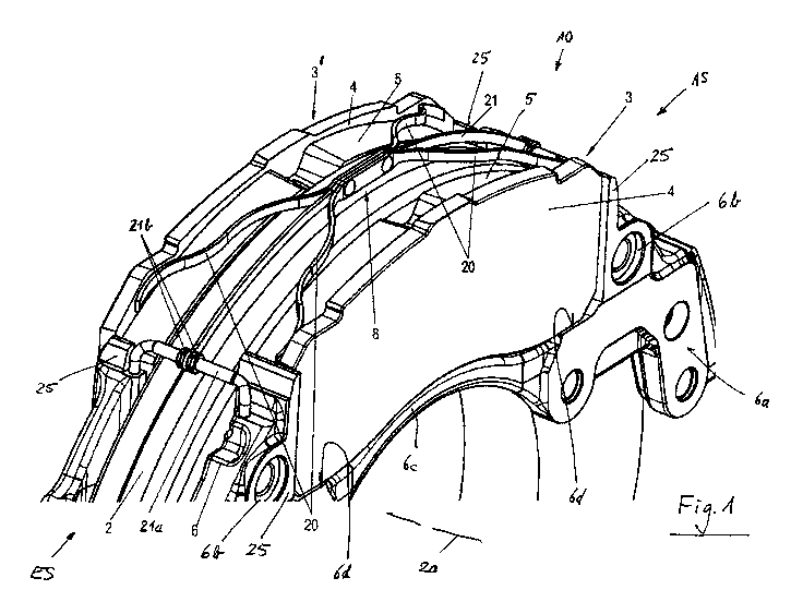
Figures 1, la and 2 show perspective views of exemplary embodiments of a
disk brake 10 according to the invention with a resetting device, from
different
viewing angles from above.
A brake caliper 1 engages over a brake disk 2 with a brake disk axis of
rotation
2a. The brake caliper 1 is attached, displaceably relative to the brake disk 2
axi-
ally in the direction of the brake disk axis of rotation 2a, to a brake
carrier 6, for
which purpose the brake caliper 1 is mounted on guide beams (not illustrated)
which are connected to the brake carrier 6 which is held in positionally
static
fashion on the vehicle.
Figure 1 shows the brake carrier 6, with the brake disk 2, the brake disk axis
of
rotation 2a of said brake disk and brake pads 3, 3', in a view from an
application
side. A fastening side 6a of the brake carrier 6 is connected to a
positionally stat-
ic component (not shown) of an associated vehicle. Furthermore, the brake car-
rier 6 has bearing receptacles 6b for the guide beams (not illustrated) for
the
mounting of the brake caliper 1 and has an application-side, curved bridge con-
nector 6c.
Also illustrated in figure 1 is a spreading device 8 with four spring arms 20
and
with a retaining bow 21. Here, the spreading device 8 is composed of two
identi-
cal spring arms 20, which are connected to one another in the central region,
and to a retaining bow 21, which is fastened by means of stirrups 21a to the
brake carrier 6, specifically to the brake carrier horns 25. For the axial
securing
of the retaining bow 21, securing means 13 are provided on the stirrup 12 so
as
to clamp the respective end of the retaining bow 21 between them.
Here, the spring arms 20 lie against two mutually oppositely situated end
regions
of the pad carrier plate 4, specifically in an edge region that protrudes at
the top
side. The ends of the spring arms 20 are likewise curved, such that sliding on
the
pad carrier plate surface during the application and release of the brake is
possi-
ble without problems. Here, spreading of the brake pads 3, 3' after a release
of
the brake is possible by way of the preload that is generated during the
applica-
tion movement.
CA 02989724 2017-12-15
17
The spreading device 8 will be discussed in detail below in a further embodi-
ment.
The brake caliper 1 comprises an application section 11, a caliper rear
section
12 and two tension struts 13. The application section 11 runs with one side
paral-
lel to the plane of the brake disk 2 on one side of the brake disk 2. The
caliper
rear section 12 is arranged on the other side of the brake disk 2, likewise so
as
to run parallel to the brake disk 2. The caliper rear section 12 is connected
to the
application section 11 at in each case one end by way of in each case one ten-
sion strut 13. Here, the tension struts 13 run substantially at right angles
to the
application section 11 and to the caliper rear section 12.
The application section 11 has an interior space in which an application
device
(not shown) of the disk brake 10 is arranged. An opening of the interior space
points toward the brake disk 2 and is closed off by means of a plate, which is
re-
ferred to as base plate 19 (see figure 1).
In this arrangement, the application section 11, the caliper rear section 12
and
the tension struts 13 define, between them, a central opening 9 which extends
over the brake disk 2. The opening 9 has an imaginary longitudinal central
line
which lies in the plane of the brake disk 2 and which connects the imaginary
cen-
ters of the tension struts 13. Furthermore, the opening 9 has a further
imaginary
transverse central line which connects an imaginary center of the application
section 11 to an imaginary center of the caliper rear section 12. The
longitudinal
central line and the transverse central line intersect at an imaginary center
point,
which in this case is referred to as the virtual center of the opening 9.
In the brake carrier 6, brake pads 3, 3' are arranged in the so-called pad
slots
between the respective two brake carrier horns 25 and lie with sections of the
bottom sides thereof on the respective pad slot base 6d. This can be clearly
seen in figure 1. The brake pads 3, 3' can, during a braking operation, be
pressed against the brake disk 2 at both sides. Here, each brake pad 3, 3' has
a
pad carrier plate 4 and, on the side facing toward the brake disk 2, a
friction pad
5 fastened to said pad carrier plate on a pad side 4a (see figure 4), which
friction
pad is, during the functional operation thereof, that is to say during a
braking op-
CA 02989724 2017-12-15
18
eration, pressed against the brake disk 2. The other side of the pad carrier
plate
4 will hereinafter be referred to as thrust side 4b (see also figure 4).
The brake pads 3, 3' are accessible, for an exchange and for maintenance,
through the central opening 9. Said brake pads can, through said central
opening
9, be inserted into their associated pad slots and removed from said pad slots
again. The pad slots are defined in each case laterally by brake carrier horns
25,
wherein the brake pads 3, 3' stand in each case with partial sections of their
bot-
tom sides on a pad slot base 6d (see figure 11).
A rotation arrow about the brake disk axis of rotation 2a indicates a main
direc-
tion of rotation for forward travel of a vehicle to which the disk brake 10 is
as-
signed. A run-in side ES and, opposite, a run-out side AS, of the disk brake
10
are defined in relation to the main direction of rotation of the brake disk 2.
Ac-
cordingly, the brake carrier horns 25 on the run-in side ES are referred to as
run-
in-side brake carrier horns 25, and those on the run-out side AS are referred
to
as run-out-side brake carrier horns 25.
A pad retaining stirrup 16 is arranged over the brake pads 3, 3' in a
transverse
direction of the opening 9 and, in the direction of the brake disk axis of
rotation
2a, between the application section 11 and the caliper rear section 12. An
appli-
cation-side retaining end 16a of the pad retaining stirrup 16 is fastened, in
a re-
taining section 14, to the application section 11 of the brake caliper 1,
wherein an
oppositely situated, rear-side retaining end 16b of the pad retaining stirrup
16 is
fixed to a retaining section 15 of the caliper rear section 12. The rear-side
retain-
ing end 16b of the pad retaining stirrup 16 is furthermore fastened by means
of a
clip 18a of a clip element 18 attached to the rear-side brake pad 3', and is
se-
cured against release by means of a securing element 17 (not described in any
more detail).
Here, the pad retaining stirrup 16 presses, by way of sections of its bottom
side,
against the clip elements 18 of the two brake pads 3, 3' and thus also against
their pad retaining springs 7, whereby the brake pads 3, 3' are held in their
pad
slots. The pad retaining springs 7 are in each case retained on the pad
carrier
plates 4 on projections 31.
CA 02989724 2017-12-15
19
Braking is performed by way of the application device arranged in a receiving
space in the application section 11 of the brake caliper 1, which application
de-
vice has, for example, a brake lever which is positioned in a dome of the
brake
caliper 1. The associated brake pad 3, referred to as action-side or
application-
side brake pad, is the first to make contact with the brake disk 2 during a
braking
operation. During the further course of the braking operation, reaction forces
that
occur cause the brake caliper 1 to be displaced in the opposite direction,
driving
the reaction-side brake pad 3, 3' along until the latter likewise comes into
fric-
tional contact with the brake disk 2. The reaction-side brake pad 3' is also
re-
ferred to as rear-side brake pad, and will hereinafter be distinguished from
the
application-side brake pad 3 by the reference designation 3'.
After a release of the brake, the two mutually oppositely situated brake pads
3, 3'
are, by way of the resetting device, released from the brake disk 2 to such an
ex-
tent that said brake disk runs freely relative to the brake pads 3, 3'.
Figure 3 illustrates a perspective view of a first function group of the
resetting
device of the exemplary embodiment of the disk brake as per figure 1. Figures
4-6 show schematic detail illustrations of the first function group as per
figures 1-
3 in various detail views.
Here, the resetting device is composed of two function groups. The first
function
group comprises at least one spreading device 8, wherein the second function
group has at least one resetting element. Here, the two function groups are
pro-
vided jointly and assist one another. It is however also possible for only one
of
the two function groups to be used.
The first function group engages with the spreading device 8 in the upper
region
of the pad carrier plates 4 of the mutually oppositely situated brake pads 3,
3', so
as to act equally counter to the application direction. The second function
group
exerts in each case thrust and/or pulling forces on the brake pads 3, 3',
likewise
counter to the application direction, by means of the resetting element(s) in
the
middle and/or lower region of the pad carrier plates 4 of the mutually
oppositely
situated brake pads 3, 3'. In this way, the brake pads 3, 3' are acted on by
the
CA 02989724 2017-12-15
resetting device with resetting forces simultaneously both in their upper
regions
and in their middle and/or lower regions.
The spreading device 8 comprises a retaining bow 21 and two spreading ele-
5 ments, which are two identical pairs of spring arms 20. The retaining bow
21 is
positionally static and forms a retainer for the pairs of spring arms 20.
Here, the retaining bow 21 is formed as a C-shaped wire and is designed for ex-
ample with a circular cross section.
The retaining bow 21 comprises a central section 26a in a central region of
the
opening 9. The central section 26a is arranged centrally in relation to the
thick-
ness of the brake disk 2. The central section 26a is adjoined on each side by
a
center limb 26 which, like the central section 26a, runs in each case in an
arc in
a circumferential direction of the brake disk 2, coaxially with respect to the
latter.
Accordingly, proceeding from the center of the opening 9, the retaining bow 21
extends to both sides in each case as far as a brake carrier horn 25 of the
pad
slot of the application-side brake pad 3.
To each end of the center limb 26 there is attached an end limb 27 which is
bent
through 90 relative to the center limb 26 and which runs toward the
respective
brake carrier horn 25. Each end limb 27 then runs parallel to the brake disk
axis
2a and is then bent downward through approximately 90 into in each case one
fastening section 27a. Each fastening section 27a is fastened in a bore 25a of
each brake carrier horn 25 and thus realizes the retention of the retaining
bow 21
with the spreading device 8 in the brake carrier 6.
Here, the retaining bow 21 thus forms a centering device for the brake caliper
1,
as the brake carrier 6, to which the retaining bow 21 is fastened, forms a
posi-
tionally static part which is mounted so as to be displaceable relative to the
brake
caliper 1, such that, after a release of the brake and a spreading movement of
the spreading device 8, that is to say after the brake pads 3 have been pushed
apart, the brake caliper 1 is guided into a centered position.
CA 02989724 2017-12-15
21
The two spring arms 20 of each pair of spring arms 20 are formed mirror-
symmetrically with respect to the central section 26 of the retaining bow 21.
The pairs of spring arms 20 are arranged opposite one another in a transverse
direction of the opening 9 such that they are fastened by way of inner ends,
which point toward the center of the opening 9, to the retaining bow 21,
wherein
their outer free ends interact with the pad carrier plate 4 of the brake pads
3, 3'.
Here, one pair of spring arms 20 is arranged to the right of the central point
of
the opening 9, wherein the other pair of spring arms 20 is arranged to the
left of
the central point of the opening 9.
Figure 4 shows an enlarged illustration of the attachment of the inner ends of
a
pair of spring arms 20 to the retaining bow 21. Figure 5 shows an enlarged
illus-
tration of a thrust section 22a of a free outer end of a spring arm 20 in
interaction
with an associated pad carrier plate 4. Figure 6 illustrates a schematic
detailed
view of the disk brake 10 in a vertical plane of the brake disk axis of
rotation 2a.
The description of one spring arm 20 of the two spring arms 20 of the pair of
spring arms 20 applies mirror-symmetrically to the other spring arm 20 of the
pair, as clearly emerges from figures 3 and 4.
Each spring arm 20 has a multiple bent body with an inner end and an outer
end.
The inner ends of the two spring arms 20 of a pair of spring arms 20 are
formed as
connecting sections 20b which run parallel to one another and which are
connect-
ed by way of a common hood-type connector 20c, by means of which a fastening
of the pair of spring arms 20 to the retaining bow 21 is formed. Here, the
intermedi-
ate section 26a of the retaining bow 21 runs, in the installed state of the
spreading
device 8, between the two parallel-running connecting sections 20b. The outer
free
end of each spring arm 20 has an end section 20d with, attached thereto, a
thrust
section 20a with an elongated hole 22 for interacting with the pad carrier
plate 4, as
will be discussed in more detail below.
The hood-type connectors 20c are connected on both sides in each case to the
connecting section 20b, which forms in each case an extension of each spring
arm 20, and said hood-type connectors are bent into a sleeve-shaped form
CA 02989724 2017-12-15
22
around the central section 26a of the retaining bow 21. In this way, each hood-
type connector 20c together with the two spring arms 20 of said pair of spring
arms 20 is mounted rotatably on the central section 26a of the retaining bow
21.
Each hood-type connector 20c has a receiving opening, pointing downwardly to-
ward the brake disk 2, in the longitudinal direction of the central section
26a of
the retaining bow 21, which receiving opening communicates with the outer con-
tour of the central section 26a of the retaining bow 21. The spring arms 20,
which
are connected in pairwise fashion to in each case one hood-type connector 20c,
are, by way of their respective hood-type connector 20c, placed onto the
central
section 26a of the retaining bow 21 from above such that the central section
26a
is received in the receiving openings of the hood-type connectors 20c.
The spreading device 8 furthermore has a clamp with a center web, which is re-
ferred to here as longitudinal connector 23. The clamp furthermore comprises
four bent-over lugs as securing elements 26c, and four hold-down means as
widened portions 26b, which are intended to push the spring arms 20 onto the
pad carrier plates 4.
The widened portions 26b lie, in each case at both sides at the transition of
the
central section 26a to the center limb 26 of the retaining bow 21, on the
connect-
ing sections 20b of the spring arms 20. In this way, the widened portions 26b
prevent a lift-off of the hood-type connectors 20c from the central section
26a. At
the same time, the widened portions 26b form an axial stop for the hood-type
connectors 20c of the respective pair of spring arms 20 in the direction of
the
longitudinal axis of the central section 26a, in each case outward from the
center
of the opening 9 toward the adjacent tension struts 13 (see figures 1, 2 and
4).
The respective two connecting sections 20b of the spring arms 20 point with
their
free ends toward the center of the opening 9 and are in each case connected in
their end regions to the securing element 26c. The securing element 26c is com-
posed of two bent-over lugs which are fixed in each case with one end in a
groove 26d in in each case one end region of the connecting sections 20b. In
this way, the securing elements 26c serve to further secure a respective hood-
type connector 20c against release from the central section 26a.
CA 02989724 2017-12-15
23
The bracing of the spreading elements is ensured by means of the bent-over
lugs as securing elements 26c of the clamp, which are bent over during the in-
stallation process and engage into the groove 26d. The spreading element is
thus secured such that it does not slip in the direction of the center and
tilt toward
the pad carrier plate 4.
By virtue of the fact that the center web (longitudinal connector 23) of the
clamp
is furthermore of continuous form, the clamp can also no longer slip axially
on
the retaining bow 21. It is thus possible to dispense with weld seams or
further
fixing means. The clamp additionally also serves as a spacer.
The spreading device is thus particularly flexible and adaptable.
The body of each spring arm 20 has multiple bends. Here, proceeding from that
end of the connecting section 20b which points towards the associated tension
strut 13 of the brake caliper 1, the body runs initially away from the
retaining bow
21 in an S-shaped arc, such that the tension-strut-side end of the S-shaped
arc
is situated with a spacing to the retaining bow 21 which amounts to for
example
2.5 times a spacing of the connecting section 20b to the retaining bow. Said
end
of the S-shaped arc transitions into a further S-shaped arc. The free end of
the
further S-shaped arc is the end section 20d, and is now spaced apart from the
retaining bow 21 by for example 2.5 times the spacing of the end of the first
S-
shaped arc to the retaining bow 21.
The thrust section 20a is attached to the end section 20d via a connecting sec-
tion which runs downwardly in an arc. Here, the thrust section 20a lies in a
tan-
gential plane relative to the brake disk 2.
The thrust sections 20a are formed, in their respective longitudinal
direction, with
the elongated hole 22 which serves as a guide section for the spring arms 20
of
the spreading device 8. The central longitudinal axes of the elongated holes
22
however run at an angle relative to a longitudinal axis of the associated pad
car-
rier plate 4, which angle lies in a range of for example greater than 0 and
less
than 45 . Here, the central longitudinal axes of the elongated holes 22 of the
CA 02989724 2017-12-15
24
thrust sections 20a intersect a common pad carrier plate 4 at an imaginary
inter-
section point, which lies on that side of the pad carrier plate 4 on which the
fric-
tion pad 5 is arranged.
In the assembled state of the disk brake 10, the thrust sections 20a interact,
by
way of their elongated holes 22, in each case with a pin 24, as can be clearly
seen in figure 5. A pin 24 is fixedly connected to the pad carrier plate 4,
for ex-
ample inserted into a bore, at each end of the pad carrier plate 4. Here, an
end,
protruding from the pad carrier plate 4, of the pin 24 extends through the
associ-
ated elongated hole 22 of the respective thrust section 20a of a spring arm 20
of
the spreading device 8. Central axes of the pins 24 run parallel to one
another
and perpendicular to the brake disk axis of rotation 2a. The elongated holes
22
permit relative movements between the spring arms 20 of the spreading device 8
and the brake pads 3, which move in the direction of the brake disk axis of
rota-
tion 2a. The spring forces of the spring arms 20 make it possible for the
brake
pads 3 to be released from the brake disk 2 and reset after a braking
operation,
as already described above.
Here, the fastening sections 20a lie in each case with bearing surfaces 29e on
a
bearing surface 4c of the respective pad carrier plate 4. The bearing surfaces
4c
of the pad carrier plate 4 run tangentially with respect to the brake disk 2
and, in
the case of each brake pad 3, lie in a plane.
The spring arms 20, the thrust sections 20a thereof and the connecting
sections
20b thereof with the hood-type connectors 20c are formed for example in one
piece
as punched and bent parts composed of spring steel strip. The spreading ele-
ments, that is to say the spring arms 20, may thus for example be formed from
in-
expensive and geometrically flexible metal sheets.
Figures 7 to 8 illustrate perspective views of a second function group of the
reset-
ting device of the exemplary embodiment of the disk brake as per figure 1.
Figure 7 shows a perspective view of a thrust side 4b of the pad carrier plate
4
of the application-side or inner brake pad 3 with a resetting element 40.
I
CA 02989724 2017-12-15
The thrust side 4b of the pad carrier plate 4 is that side of the pad carrier
plate 4
which does not bear a friction pad 5, and which is in contact either with the
appli-
cation device or with the caliper rear section 12.
5 The resetting element 40 provides assistance of the resetting movement of
the
application-side brake pad 3 from the brake disk 2 after a braking process.
Here,
the resetting element 40 engages with a section in a lower region on the
respec-
tive pad carrier plate 4 in addition to the engagement point(s) at the top
side of
the spring arms 20, wherein the resetting element 40 is connected with a
differ-
10 ent section to a section positionally static relative to the resetting
element 40, for
example brake caliper 1 and/or brake carrier 6.
For this purpose, the resetting element 40 in the embodiment as per figure 7
is
fastened, with a section in a lower region of the pad carrier plate 4 on the
thrust
15 side 4b thereof, to a retaining peg 32. The retaining peg 32 may self-
evidently al-
so be designed in some other form, for example a screw, bolt or the like. Fur-
thermore, the resetting element 40 is attached with a further section in a
lower
region of the base plate 19 (see also figure 1) of the application section 11
of the
brake caliper 1.
In this regard, figure 8 shows a schematic perspective illustration of base
plate
19 and transparent pad carrier plate 4 with engagement of the resetting
element
40.
Here, the resetting element 40 is a spring element with a central section 41,
two
spring arms 42 and two fastening sections 43 with in each case one U-shaped
lug 44 with a limb 44a. The central section 41 and the spring arms 42 are pro-
duced for example from a flat spring steel strip, wherein the fastening
sections
43 may be conventional sheet steel.
The central section 41 is connected centrally to the retaining peg 32 by means
of
a clamping/claw-type connection. At each side, the central section 41
transitions
symmetrically into the respective spring arm 42. Each spring arm 42 extends to
the left and to the right from the central section 41 in a lower region along
the
pad carrier plate 4, and is shaped correspondingly to the contour thereof. The
,
CA 02989724 2017-12-15
26
ends of each spring arm 42 are connected in each case to the fastening section
43. Each fastening section 43 is shaped such that the bends of the U shapes of
the lug 44 and the limbs 44a are aligned with one another and lie in a
tangential
direction with respect to the brake disk axis of rotation 2a. That limb of the
fas-
tening sections 43 which points in each case toward the base plate 19 runs out-
ward as a lug 44 and widens so as to have in each case one fastening bore 44b
for the fixing, by means of screws of the base plate 19, to said base plate.
The
screws may also be existing fastening screws of the base plate 19.
After a braking process, the brake pads 3, 3' are firstly pushed apart from
one
another, and thus reset away from the brake disk 2, again by the spring arms
20
of the spreading device 8. At the same time, the resetting element 40, which
may
also be installed in already prestressed fashion, is stressed during the
braking
process owing to its positionally static fixing of its fastening sections 43
to the
base plate 19, and can, after the braking process, additionally retract the
brake
pad 3 from the brake disk 2 by application of a pulling force thus stored.
Figures 9-17 show perspective views of variants of the second function group
of
the resetting device.
Figure 9 shows a first variant of the second function group of the resetting
de-
vice as per figure 8. The fastening sections 43 are identical to those of the
em-
bodiment as per figure 8. By contrast thereto, the resetting element 40 of
said
first variant is formed from a spring wire. The spring wire has two spring
arms 45
which are connected by way of a central section 45a. The free ends of the
spring
arms are fixedly connected as end sections 45b to the respective fastening sec-
tion 43, for example by welding. The central section 45a is in this case a
constit-
uent part of the spring wire and is fastened to a retainer 33 on the bottom
side of
the pad carrier plate 4.
The retainer 33 is in this case formed as a bolt with a head plate, the
diameter of
which is larger than the bolt body. The retainer 33 is arranged in a recess
33a of
the pad carrier plate 4 in the bottom side thereof. Here, the central section
45a is
looped around the region of the bolt between the base of the recess 33a and
the
head plate of the bolt within the recess 33a.
CA 02989724 2017-12-15
27
The function of the resetting element 40 is as described in conjunction with
the
embodiment as per figures 7-8.
Figure 10 illustrates a second variant of the second function group and
further-
more shows the right-hand half of the installed application-side brake pad 3
in its
associated pad slot with the brake carrier 6. The brake pad 3 is pushed into
the
pad slot by the pad retaining stirrup 16, the application-side retaining end
16a of
which is visible, via the pad retaining spring 7, which is retained on the
projec-
tions 31. Here, the brake carrier 6 is illustrated with its fastening side 6a,
in which
multiple fastening holes (not designated) for the fastening to a positionally
static
part of an associated vehicle are formed. The right-hand, in this case (see
figure
1) the run-out side, brake carrier horn 25 with a bearing receptacle 6b
arranged
therebelow is also shown. The bearing receptacle 6b receives a bearing beam of
the longitudinal bearing of the brake caliper 1.
In the second variant, the second function group comprises two resetting ele-
ments 46, of which figure 10 shows only the right-hand resetting element at
the
right-hand bottom side of the pad carrier plate 4. The secondary setting
element
46 of this second variant is arranged, and correspondingly constructed, at the
left-hand bottom side (not shown here, but easily imaginable) of the pad
carrier
plate 4, mirror-symmetrically with respect to the right-hand resetting element
46.
The resetting element 46 comprises a first spring arm 47 with a clamping end
47a and with a connection, comprises a second spring arm 48 with a connection
48a, and comprises a fastening section 49 with an opening 49a.
The first spring arm 47 is plugged with its clamping end 47a into a retainer
34
and is fastened to the latter, for example by means of a clipping ac-
tion/indentation action or the like. Here, the retainer 34 protrudes on the
right-
hand lower corner of the thrust side 4b of the pad carrier plate 4 and may for
ex-
ample be cast on during the production of the pad carrier plate 4.
The first spring arm 47 extends, in the lower region in front of the thrust
side 4b
of the pad carrier plate 4, from the retainer 34 toward the left in the
direction of
CA 02989724 2017-12-15
28
the center of the pad carrier plate 4, over a length which corresponds to
approx-
imately one third of the length of the pad carrier plate 4. Then, the first
spring 47
transitions into the connection 47b, which is bent through approximately 1800
outward, that is to say toward the application section 11.
The connection 47a in turn then transitions into the second spring arm 48,
which
extends oppositely to the first spring arm 47 and parallel to the latter as
far as
over the retainer 34. The connection 48a is formed as a type of cranked for-
mation in the direction of the pad carrier plate 4, and is connected to the
fas-
tening section 49.
The fastening section 49 lies with its large opening 49a in front of the
opening of
the bearing receptacle 6h of the brake carrier 6 and coaxially with respect
there-
to. After the fastening of the brake carrier 6, it is thus also the case that
the fas-
tening section 49 is fixed in a positionally static manner between the
fastening
side 6a and the positionally static part of the associated vehicle.
Figure 10 furthermore shows a variant of the retaining bow 21 in which the end
limbs 27 on the sides facing toward one another are equipped, in each case on
an end section 28, with a lug 29, on which lugs there are held pegs 30 which
en-
gage into bores (not designated) of the brake carrier horns 25. The lug 29
lies on
a planar face side of the brake carrier horn 25. The peg 30 may be in the form
of
a rivet and plugged into the bore of the brake carrier horn 25. It is also
possible
for the peg 30 to be integrally formed on the brake carrier horn 25, or to
have al-
ready been fixedly inserted as a separate component.
The two resetting elements 46 may be produced for example as punched and
bent parts from a flat spring steel material.
The function of the two resetting elements 46 has already been described
above,
wherein the positionally static section for the fixing of the resetting
elements 46 is
in this case the brake carrier 6, and the pulling forces are introduced by the
re-
tainers 34 at two corner points of the pad carrier plate 4.
CA 02989724 2017-12-15
29
Figure 11 illustrates a third variant of the second function group with a
central
resetting element 50.
The resetting element 50 is arranged centrally in a vertical direction on the
thrust
side 4b of the application-side pad carrier plate 4 and is fastened both to
the top
side and to the bottom side of the pad carrier plate 4, wherein a positionally
static
fixing of one end of the central resetting element 50 is formed centrally on
an ap-
plication-side bridge connector 6c of the brake carrier 6.
The central resetting element 50 has two lateral longitudinal members 51 which
are arranged parallel to one another and the upper ends of which, as gripping
sections 51a, engage fixedly as clips around the top side of the pad carrier
plate
4 on the left and on the right adjacent to the clip element 18. In the same
way,
the two longitudinal members 51 are, at their bottom ends, equipped with grip-
ping sections 51b of said type, which engage fixedly as clips around the
bottom
side of the pad carrier plate 4.
The two longitudinal members 51 are connected, below the upper gripping sec-
tions 51a, by means of a transverse connector 52. At the bottom side, the
longi-
tudinal members 51 are, above the lower gripping sections 51b, connected to in
each case one transverse connector 53, to which in each case one further longi-
tudinal member 54 is attached. The further longitudinal members 54 extend up-
ward in each case parallel to the outer longitudinal members 51 and are con-
nected at their upper ends, below the transverse connector 53, to a further
trans-
verse connector 55.
In the center of the further transverse connector 55 there is attached a
central
longitudinal member 56, which extends downward between the two longitudinal
members 54 beyond the gripping sections 51b and ends in a dedicated gripping
section 56a. Said central gripping section 56a is fixed centrally in a
suitable
manner, for example by means of a gripping action, to the positionally static
bridge connector 6c of the brake carrier 6.
The function is as described above.
CA 02989724 2017-12-15
Figures 12 to 15 show variants of central resetting elements 50 on the thrust
side
4b of the application-side pad carrier plate 4 of the application-side brake
pad 3
together with the pad retaining stirrup 16.
5 The fixing of the resetting elements 50 to the pad carrier plate 4 is
arranged in
each case in the lower region thereof, wherein the positionally static fixing
of the
resetting elements 50 is provided in each case on the application-side
retaining
end 16a of the pad retaining stirrup 16. The function of the resetting
elements 50
has already been discussed above.
The resetting element 50 as per figure 12 has a spring body 57 in wire form
with
two longitudinal members 58 arranged parallel to one another. The longitudinal
members 58 are in this case connected at the bottom by means of a transverse
connector 58a, which is held centrally under a retaining angle piece 35 in the
lower region of the pad carrier plate 4. The longitudinal members 58 and the
transverse connector 58a may be produced in one piece from spring wire as a
bent part.
An upper end of one longitudinal member 58, in this case the right-hand
longitu-
dinal member, is bent through approximately 90 toward the center as an end
section 58b, and is attached, in a retainer section 59b of a retainer 59, to
the ap-
plication-side retaining end 16a of the pad retaining stirrup 16. The upper
end of
the other (left-hand) longitudinal member 58 is similarly bent through approxi-
mately 90 toward the center as an end section 58c and fastened to the
retainer
59. This is not shown here but is easily understandable. Here, the bent end
sec-
tions 58b, 58c are arranged offset with respect to one another in a vertical
direc-
tion.
Here, the retainer 59 is formed as a punched and bent part with clip-like
retainer
sections 59a, which engage around sections of the retaining end 16a of the pad
retaining stirrup 16.
The retaining angle piece 35 is, at its bottom side, fastened by means of a
limb
35a to the thrust side 4b of the pad carrier plate 4, and extends in this case
up-
ward approximately over one quarter of the vertical length of the pad carrier
plate
CA 02989724 2017-12-15
31
4. Here, the transverse connector 58a is retained approximately centrally be-
tween the thrust side 4b of the pad carrier plate 4 and the bottom side of the
re-
taining angle piece 35.
In figure 13, the resetting element 50 is designed as in figure 12 but is
arranged
having been rotated through 1800. The transverse connector 58a is attached be-
low the application-side retaining end 16a of the pad retaining stirrup 16.
The
end sections 58b and 58c are received, and rotatably fixed, in a block-like
retain-
er 36 in suitable retaining openings 36a. The retainer 36 may be cast on
during
the production of the pad carrier plate 4.
Figure 14 shows a further resetting element 50 with a single spring body 60,
which is plugged with a lower end section 60a into a retaining opening 37a in
a
retaining stirrup 37. The upper end of the spring body 60 is designed, in a
spring
winding, as a fastening section 60b, and is attached to a retainer 59 similar
to
that described in conjunction with figure 12, wherein the attachment may be
dif-
ferent; for example, the fastening section 60b is plugged in or is welded to
the re-
tainer 59. Here, the spring body 60 is equipped with two bends with relatively
large radii. The retaining stirrup 37 may be cast onto the thrust side 4b of
the pad
carrier plate 4.
A further variant is shown in figure 15, wherein the resetting element 50 is
de-
signed as a spring plate 61. Here, a width of the spring plate 61 corresponds
for
example to twice a thickness of the pad carrier plate 4 in the direction of
the
brake disk axis of rotation 2a. The spring plate 61 is, by means of an end
section
61a, in engagement with a retaining stirrup 38 in the retaining opening
thereof,
as has already been described above. A fastening section 61b of the spring
plate
61 is attached to the retainer 59, already described above, on the application-
side retaining end 16a of the pad retaining stirrup 16, for example by being
plugged in, hooked in, welded on or the like.
The above examples of the second function group of the spreading device 8 re-
lated in each case to the application-side brake pad 3. They may self-
evidently
also be provided on the rear-side brake pad 3'.
CA 02989724 2017-12-15
32
Figures 16 and 17 illustrate examples of variants of resetting elements for
the
rear-side brake pad 3'.
Figure 16 shows a schematic perspective view of the thrust side 4b of the pad
carrier plate 4 of the rear-side brake pad 3' in its associated pad slot in
the brake
carrier 6 between the brake carrier horns 25. Furthermore, the pad retaining
stir-
rup 16 is illustrated with its rear-side retaining end 16b, wherein the
retaining end
16b is equipped with the clip 18a and the securing element 17 (not discussed
in
any more detail).
The resetting element 62 comprises a central section 63 with two connecting
sections 63a, two spring arms 64 with in each case one spring end 64a, two fur-
ther connecting sections 65, and two further spring arms 66 with in each case
one clip end 66a.
The central section 63 is arranged in a lower edge region of the thrust side
4b of
the pad carrier plate 4 and, like said region, is of substantially curved
form. At
each end of the rounded portion, the central section 63 has, on both sides,
the
connecting section 63a.
In each case one of the spring arms 64 is attached to each connecting section
63a in the lower region. Each spring arm 64 extends in a tangential direction
in
relation to the brake disk 2 as far as over a side of the respective brake
carrier
horn 25, wherein the respective spring end 64a on a side surface of the respec-
tive brake carrier horn 25.
Above each spring arm 64, in each case one of the further connecting sections
65 is connected by means of an arm 65a to the respective connecting section
63a. The arms 65a extend, in each case parallel to the spring arms 64, on the
thrust side 4b from the associated connecting section 63a as far as the respec-
tive side edge of the pad carrier plate 4, and transition into the associated
con-
necting section 65.
The connecting sections 65 are adapted to the external shape of the corner re-
gions of the pad carrier plate 4, are widened and rounded diagonally toward
the
CA 02989724 2017-12-15
33
center of the pad carrier plate 4, and transition in each case upwardly into
the
spring arm 66.
Each spring arm 66 extends along a side region of the pad carrier plate 4 on
the
thrust side 4b as far as an oblique upper side section 4d of the pad carrier
plate
4. Each upper end of the spring arms 66 is equipped with one of the clip
sections
66a, which are in each case fastened, so as to engage over an oblique side sec-
tion 4d, to the pad carrier plate 4.
It is also possible for the central section 63 to be fastened by means of one
or
more clip sections (not shown), for example, to the pad carrier plate 4.
In this way, the resetting element 62 is firstly attached by means of the clip
sec-
tions 66a of the spring arms 66 to the pad carrier plate 4 of the rear-side
brake
pad 3', and is secondly fixed in a positionally static manner by means of the
spring arms 64, with the spring ends 64a thereof, to the brake carrier horns
25.
Said fastening may also already effect a preload of the resetting element 62.
As discussed above, during a braking process, the resetting element 62 is
stressed and, by means of the fastening to the pad carrier plate 4, exerts
pulling
forces on said carrier plate in order to reset the rear-side brake pad 3' away
from
the brake disk 2 after a braking process.
Figure 17 shows a sectional view, in a plane running through the brake disk
axis
of rotation 2a, of the disk brake with the rear-side or outer brake pad 3'
with a fur-
ther resetting element 67.
The resetting element 67 is formed as a type of leaf spring with a spring body
68
with in each case one spring end 68a, 68b. One spring end 68a is articulated,
in
a lower region of the rear-side pad carrier plate 4 on the thrust side 4b
thereof,
on a retaining stirrup 39. The other spring end 68b, with a suitable design,
digs
into a retaining section 12a of the caliper rear section 12 of the brake
caliper 1. It
is possible for the resetting element 67 to be provided centrally, or for two
such
resetting elements 67 to be provided at the corners, or else for multiple such
re-
CA 02989724 2017-12-15
34
setting elements to be provided so as to be distributed over the length of the
lower region of the pad carrier plate 4.
Figure 18 illustrates a schematic sectional view of a further variant of the
second
function group of the spreading device 8 a resetting element 69 in a sectional
view in a plane, running through the brake disk axis of rotation 2a, of the
disk
brake with the brake pads 3, 3'.
In this variant, the resetting element 69 is of stirrup-like form with are two
mutual-
ly oppositely situated spring arms 71, 72 in spring form, for example leaf
and/or
wire springs. Each spring arm 71, 72 is attached by means of its upper end in
each case to a central section 70 via a connecting bend 70a, 70b. The central
section 70 of the resetting element 69 is fastened to the central section 26a
of
the retaining bow 21 of the spreading device 8, wherein said central section
70 is
for example bent around the central section 26a.
From a lower end of each connecting bend 70a, 70b, each spring arm 71, 72 ex-
tends downward in the direction of the brake disk axis of rotation 2a as far
as into
the region of the bottom side of each brake pad 3. Each spring arm 71, 72 has
a
free end with in each case one thrust-imparting limb 71a, 72a, and is arranged
in
each case in an elongate intermediate space between friction pad 5 and the pad
side 4b of the pad carrier plate 4, wherein the thrust-imparting limbs 71a,
72a are
each case in contact with the respective pad carrier plate 4.
In this embodiment, the spring arms 71, 72 of the resetting element 69 each ex-
ert a thrust force on the brake pads 3, 3' in the direction of the brake disk
axis of
rotation 2a pointing away from the brake disk 2, whereby, after every braking
process, the brake pads 3 are acted on with a force for a resetting action in
the
lower region by the spring arms 71, 72 of the resetting element 69 as well as
by
the spring arms 20 of the spreading device 8.
Figure 19 shows a schematic detail sectional view of the disk brake 10
according
to the invention as per figure 1 with guide elements 73.
CA 02989724 2017-12-15
Each guide element 73 has a fastening section 73a and a guide section 73b fas-
tened thereto. The fastening section 73a is formed as a type of lug and
transitions,
at its bottom side, firstly into an arm 73c, which is bent out of a plane of
the fas-
tening section 73a, of the guide section 73b. Here, the arm 73c is bent up by
ap-
5 proximately 45 . Attached to the free end of the downwardly bent-away arm
73c is
an end section 73d which is bent up from a plane of the arm 73c by
approximately
900 in the same bending direction as the arm 73c, wherein a bearing section
73e is
formed.
10 The guide elements 73 are attached in the lower region of each pad
carrier plate 4
of the brake pads 3, 3' such that the bearing sections 73d thereof lie on the
respec-
tive pad slot base 6d (see also figure 11). Here, the fastening sections 73a
are fas-
tened in each case on the thrust side 4b of a respective pad carrier plate 4
by
means of a fastening element 74, for example rivet. It may be provided that,
on
15 each pad carrier plate 4, a guide element 73 is arranged in the center,
or multiple
guide elements 73 are arranged so as to be distributed over the length of the
pad
carrier plate 4.
The guide elements 73 enlarge a bearing surface of the respective pad carrier
plate 4 on the pad slot base 6d in the direction of the brake disk axis of
rotation 2a.
20 Here, the guide elements 73 do not exert a force on the associated brake
pads 3,
3', but rather in each case define for the brake pads 3, 3' a certain
preferred direc-
tion in order to prevent tilting of the brake pads 3, 3' when the brake pads
3, 3', for
example by means of the spring arms 20 of the spreading device 8, as a result
of
their exertion of force on the top side of the pad carrier plates 4, are moved
back
25 after a braking process as already discussed above.
The invention is not restricted by the exemplary embodiments described above.
It
may be modified within the scope of the appended claims.
CA 02989724 2017-12-15
36
LIST OF REFERENCE DESIGNATIONS
1 Brake caliper
2 Brake disk
2a Brake disk axis of rotation
3, 3' Brake pad
4 Pad carrier plate
4a Pad side
4b Thrust side
4c Contact surface
4d, e Side section
5 Friction pad
6 Brake carrier
6a Fastening side
6b Bearing receptacle
6c Bridge connector
6d Pad slot base
7 Pad retaining spring
8 Spreading device
9 Opening
10 Disk brake
11 Application section
12 Caliper rear section
12a Retaining section
13 Tension strut
14, 15 Retaining section
16 Pad retaining stirrup
16a, 16b Retaining end
17 Securing element
18 Clip element
18a Clip
19 Base plate
20 Spring arm
20a Thrust section
20b Connecting section
CA 02989724 2017-12-15
37
20c Hood-type connector
20d End section
20e Bearing surface
21 Retaining bow
21a Stirrup
21b Securing means
22 Elongated hole
23 Longitudinal connector
24 Pin
25 Brake carrier horn
25a Bore
26 Center limb
26a Central section
26b Widened portion
26c Securing element
26d Groove
27 End leg
27a Fastening section
28 End section
29 Lug
Peg
31 Projection
32 Retaining peg
33 Retainer
25 33a Recess
34 Retainer
Retaining angle piece
35a Limb
36 Retainer
30 36a Retaining opening
37, 38, 39 Retaining stirrup
37a, 38a, 39a Retaining opening
Resetting element
41 Central section
35 42 Spring arm
I
CA 02989724 2017-12-15
38
43 Fastening section
44 Lug
44a Fastening hole
45 Spring arm
45a Central section
45b End section
46 Resetting element
47 Spring arm
47a Clamping end
47b Connection
48 Spring arm
48a Connection
49 Fastening section
49a Opening
50 Resetting element
51, 54, 56 Longitudinal member
51a, 51a, 56a Gripping section
52, 53, 55 Transverse connector
57 Spring body
58 Longitudinal member
58a Transverse connector
58b, 58c End section
59 Retaining means
59a Retainer section
59b Retainer lug
60 Spring body
60a End section
60b Fastening section
61 Spring plate
61a End section .
61b Fastening section
62 Resetting element
63 Central section
63a Connecting section
64 Spring arm
1
CA 02989724 2017-12-15
39
64a Spring end
65 Connecting section
65a Arm
66 Spring arm
66a Clip end
67 Resetting element
68 Spring body
68a Clamping end
68b Claw end
69 Resetting element
70 Central section
70a, 70b Connecting bend
71,72 Spring arm
71a, 72a Thrust-imparting limb
73 Guide element
73a Fastening section
73b Guide section
73c Arm
73d End section
73e Bearing section
74 Fastening element
AS Run-out side
ES Run-in side