Note: Descriptions are shown in the official language in which they were submitted.
84116538
BAG WITH LOCKABLE DRAWSTRING
The invention relates to a drawstring bag made of two
face panels that are interconnected at side edges, a casing for a
drawstring being provided at a mouth of the drawstring bag and a
drawstring provided in this casing, the drawstring being connected
to the drawstring bag at one end and freely accessible on the other
end.
Such drawstring bags used for example as trash bags are
known. They are manufactured in an appropriate manner such that
io three sides of the drawstring bag are closed, thus forming a
container for receiving any manner of objects. The fourth side is
open in order enable objects to be placed into the bag. After
filling, the bag can be closed in an inherently known manner by
pulling on the drawstring that is confined in its casing. As a
result of this pulling on the drawstring, the drawstring is pulled
out of the casing and the fourth side of the drawstring bag, which
has heretofore been open, is drawn together, thereby closing the
bag.
This type of closure for drawstring bags by a drawstring
has inherently proven its worth. However, depending on the type of
object to be introdUced into the bag, and also depending on the
handling of the bag, it is possible for the part of the drawstring
that has been pulled out of this casing to slip back into this
casing. This automatically has the effect that the previously
closed drawstring bag opens at least partially, or even completely
in the worst case, and the objects that were previously placed into
- 1 -
Date Regue/Date Received 2022-07-18
84116538
the bag can intentionally or unintentionally come out of the bag.
Particularly in a case in which trash has been filled into the bag,
for example, it is disadvantageous if the bag can open up again.
It is therefore the object of the invention to improve a
known drawstring bag to the effect that, once the bag is closed, it
remains closed. If at all, it should only be possible to open the
bag again under the application of a substantial amount of force or
against a resistance.
According to some embodiments of the invention, there is
provided a drawstring bag, comprising two face panels
interconnected at side edges, a casing for a drawstring being
provided at a mouth of the bag, and a drawstring being provided in
this casing, wherein the drawstring is connected at one end to the
bag and freely accessible at the other end, wherein a locking strip
is mounted on the drawstring between the end connected to the bag
and the freely accessible end of the drawstring and comes to rest
against an opening end of the casing for the drawstring when it has
left this casing.
According to the invention, a locking strip is provided
between the end that is connected to the bag and the freely
accessible end of the drawstring that comes to rest against an
opening edge of the casing for the drawstring when it has left this
casing. When the bag has been filled and is to be closed, one pulls
on the drawstring in the usual manner so that it largely leaves the
casing in which it has been located up to now. The side edge of the
opening of the bag is drawn together along the drawstring, so that
this opening is closed as a result. At the same time, the locking
strip is also moved out of the casing as a result until it is no
longer in the casing and is visible from the outside. This means
that the locking strip comes to rest against an opening edge of the
casing for the drawstring when it has left this casing, and the
- 2 -
Date Regue/Date Received 2022-07-18
84116538
drawstring is advantageously and effectively prevented from sliding
back into the casing. At the same time, this has the consequence
that the already-closed opening of the bag remains closed, because,
by virtue of the locking strip, it is not possible for the
drawstring to slip back into its casing. The
- 2a -
Date Regue/Date Received 2022-07-18
CA 02990508 2017-12-21
. =
31243 SN 15/572,912
Transl. of W02016/202988
locking strip now locks quasi only a small portion of the
drawstring within the casing, while the majority of the drawstring
is located outside of the casing. Only if a substantially greater
force is applied (in order to overcome the locking strip during the
return into the casing) or if the locking strip is manually guided
back into the casing, for example, is it possible to open the bag,
and this opening process is then carried out deliberately and no
longer inadvertently as in the prior art.
The locking strip can be formed in various ways.
In one embodiment of the invention, the locking strip is
glued to the drawstring. Alternatively or in addition, the locking
strip is welded to the drawstring. Both possibilities offer the
advantage that various ways exist for fastening the locking strip
to the drawstring. For instance, the locking strip can be attached
to the drawstring before it is threaded into the casing. On the
other hand, it is conceivable for the locking strip to be fastened
to the drawstring when the drawstring has already been threaded
into the casing.
In a development of the invention, the locking strip is a
piece that is separate from the face panel and the drawstring,
particularly a patch of plastic film, a paper strip, or the like.
This offers the advantage of geometric freedom with respect to the
size, extension, thickness, and material of the film.
In a development of the invention, the locking strip is
not formed as a part that is separate from the bag or drawstring;
instead, it is formed from a face panel of the bag, the so-called
parent material, preferably by a die-cutting process. This offers
- 3 -
31243T1R1WPD
CA 02990508 2017-12-21
31243 SN 15/572,912
Transl. of W02016/202988
the advantage of especially simple manufacturing, since the bag can
first be produced with the casing for the drawstring, after which
the drawstring can be introduced into the casing. The locking
strip is then die-cut, perforated, or the like from the face panel,
with the doe-cut part being permanently connected to the drawstring
subsequently, simultaneously, or beforehand. Once again, this can
be achieved by gluing, welding, or the like.
Just like web or comparable connections, a connection
between the locking strip and the face panel of the bag offers the
io advantage that the drawstring is first set in a defined position in
the casing. Only after the bag has been filled is it possible to
pull on the freely accessible part of the drawstring, at which
point the locking strip is detached from the face panel under the
application of a minimal force. Alternatively, the locking strip
is can also be completely separated from the face panel, even if it is
formed by it.
For example, there are two possibilities for the making
the casing for the drawstring.
For one, in a development of the invention, the casing
20 for the drawstring is formed as a channel extending along an upper
edge of the face panel. This means that the casing for the
drawstring is channel-shaped in the upper edge region of the face
panel, with only the upper edge of the face panel being used to
form the casing. The handling of additional parts for the
25 formation of the bag can thus be avoided, rendering the manufacture
of such a drawstring bag especially advantageous, because, in this
- 4 -
312431-131WM
=
CA 02990508 2017-12-21
31243 SN 15/572,912
Transl. of W02016/202988
case as well, the locking strip is optionally formed in an
especially advantageous manner from the face panel.
As an alternative, in one development of the invention
the casing for the drawstring is formed by an overlay strip that is
connected along its edges to the face panel. Another configuration
for the casing is thus made available in which a web strip is used
that is placed on the surface of the face panel and connected by
its side edges to the face panel. The casing for the drawstring is
thus produced. Here, too, it is conceivable either for the locking
strip to be detached from the face panel or the locking strip, or
it is also conceivable for the locking strip to again be formed by
a portion of the face panel or of the overlay strip.
In an especially advantageous embodiment, the bag has a
sinusoidal upper bag edge (so-called sine bags), with a hand hole
optionally provided in the sinusoidal bag edge. The hand hole can
be used to hang or carry the bag.
Drawstring bags are formed as trash bags, simple flat
bags, bread bags, freezer bags, or the like. Preferably, both the
bag itself and the drawstring are made of the same material,
particularly plastic, thus advantageously improving recycling.
Various plastics are also conceivable. Likewise, it is conceivable
for the material of the bag and the material of the drawstring to
be the same or different colors, which also entails advantages with
respect to recycling. For instance, the fact that the bag and
drawstring are different colors can indicate that they are made of
different materials. Conversely, the same color means the same
material.
- 5 -
31243Tiz1mm
CA 02990508 2017-12-21
31243 SN 15/572,912
Transl. of W02016/202988
Whether made of the same or a different material than the
bag, the drawstring can be thicker (enabling it to withstand
greater tension, for example by virtue of having a greater
thickness than the face panel of the bag) and/or elastic. With
such an elastic drawstring, it is possible - when used in a
drawstring bag designed as a trash bag in a rigid trash container,
for example - to place the upper edge of the trash bag around the
upper edge of the trash container and to tighten the elastic
drawstring around this upper container edge.
While it was assumed above that the drawstring is an
elongate plastic film, it can also have a different design. For
instance, the drawstring can be a cord, string, or the like (made
of plastic, natural material, or a combination thereof). In this
embodiment, as well as the embodiment made of plastic, the locking
strip placed thereon need not have the shape of a strip. If the
drawstring is formed as an elongate strip, the locking strip is
preferably square, rectangular, round, or oval-shaped. If the
drawstring is formed as a cord, string, or the like, the locking
strip is formed as a knot or connected to the string as a clip,
thickening, or the like. Regardless of how it is configured, it is
important that the shape enable this locking strip, knot, clip, or
the like to catch on an opening edge of the casing for the
strip-like drawstring, the cord, the string, or the like after it
has left this casing.
In the following, the invention will be explained in
further detail with reference to two embodiments, to which it is
not however limited.
- 6 -
3124311R1WPID
CA 02990508 2017-12-21
31243 SN 15/572,912
Transl. of W02016/202988
FIG. 1 shows a drawstring bag with a lockable drawstring;
FIG. 2 shows detail D of FIG. 1;
FIG. 3 shows a sine bag with a lockable drawstring; and
FIG. 4 shows a detail of FIG. 3.
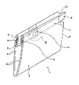
To the extent that it is shown in detail, a drawstring
bag is shown in FIG. 1 that consists of two opposing face panels 2,
3. The face panels 2 and 3 have side edges 4 that interconnect the
two face panels 2 and 3. In the lower part when looking at FIG. 1,
the face panels 2 and 3 are folded over in approximately a U-shape,
so that this fold and the connection of the two face panels 2 and 3
by their side edges 4 results in a drawstring bag 1 that is
initially closed on three sides. At the upper end when looking at
FIG. 1, the bag 1 is initially open. Channels 5 and 6 are formed
by the upper edges of the face panels 2 and 3 at the upper end of
the bag 1. As a result of the folding-over of the upper edges of
the face panels 2 and 3 to form the channels 5 and 6, a casing is
created on both sides for a drawstring 7. The drawstring 7 has a
fixed drawstring end 8 at one of "maksb8the side edges 4. It
extends thence along the channel 5 and 6 and projects out at the
side edge 4 opposite from the fixed drawstring end 8 and forms
there an accessible, free drawstring end 9. At the free drawstring
end 9, a cutout 10 can but need not be provided in the upper edge
region of the bag 1. If this cutout 10 is present, the free
drawstring end 9 (particularly where it loops from the channel 5
toward the channel 6) advantageously ends there in alignment with
the side edge 4. It is also conceivable, however, to have the free
drawstring end 9 project beyond the side edge 4. Moreover, an
- 7 -
312431-MWPD
CA 02990508 2017-12-21
31243 SN 15/572,912
Transl. of W02 16/202988
additional aid can be provided in this region of the free
drawstring end 9 for gripping (tag).
A locking strip 11 is provided on the drawstring 7 that
is optionally provided within the channel 5 and thus not visible
and/or not accessible. This is the case particularly if the
locking strip 11 was fastened to the drawstring before the
drawstring 7 was threaded into the channel 5. Alternatively, the
locking strip 11 is accessible and/or visible from the outside
either if a hole has been provided in the channel 5 or if the
locking strip 11 is formed from the face panel 2 by die cutting,
perforation, or the like. If the drawstring 7 is in the channel 5,
for example, the locking strip 11 can be die-cut after the face
panel 2 has been glued, welded, or the like to the drawstring 7
before the die cutting.
This configuration of detail D is very clearly visible in
FIG. 2. There, it is shown that the drawstring 7 has been provided
with the locking strip 11 by the permanent and non-detachable
interconnection of these two parts by a bond 12. As mentioned
previously, this can be made a gluing process, a welding process,
or a combination thereof or the like. The channel 5 has upper and
lower edges 51 and 52 . The locking strip 11 itself has an upper
edge 111 and a lower edge 112. If the two edges 111 and 112 lie
outside of the opening of the channel 5, which is defined by the
edges 51 and 52, it is necessary to pull on the drawstring 7 with
somewhat greater force at its free drawstring end 9 in order to
pull the larger-sized locking strip 11 into the casing, that is,
into the channel 5. If the edges 51 and 111 on the one hand and 52
- 8 -
312431R1wm
CA 02990508 2017-12-21
31243 SN 15/572,912
Transl. of W02016/202988
and 112 on the other hand are aligned, this indicates that the
locking strip 11 can but need not be formed from the face panel 2.
In this case as well, it is conceivable for the edges 51/111 and
52/112 to be aligned and for the locking strip 11 to be a component
that is separate from the face panel 2.
As an alternative to the bag 1 illustrated in FIG. 1,
FIG. 3 shows a sine bag with the same principle of the locking
strip 11.
The sine bag according to FIG. 3 differs from the bag
according to FIG. 1 in that it has a sinusoidal upper bag edge 13
in which a hand hole 14 is optionally formed, particularly die cut.
A lower gusseted bag bottom 15 is present on the side
opposite the opening side at the sinusoidal upper bag edge 13 that
offers the advantage that, as the two face panels 2 move apart, the
initially folded-over bag bottom 15 offers a greater surface for
placing objects after the sine bag is filled.
In the embodiment according to FIG. 3 (alternatively to
the bag according to the exemplary embodiment in FIG. 1), the
channel 5 and 6 is formed by an additional overlay strip 16 that is
placed with its side edges (fastening seam 17) on the surface of
the face panel 2 and non-detachably connected thereto. The
fastening seam 17 can be continuous, segmental, or punctiform and
achieved by gluing, welding, or the like. Here, too, just as in
FIG. 1, the drawstring 7 is securely attached with its fixed
drawstring end 8 at one of the side edges 4, and the free
drawstring end 9 is freely accessible at the opposite side edge
away from the fixed drawstring end 8.
- 9 -
312431R1wm
CA 02990508 2017-12-21
31243 SN 15/572,912
Transl. of W02016/202988
FIG. 4 shows the detailed view D according to FIG. 3.
It holds for both embodiments that, after the bag is
filled, the drawstring 7 can be gripped at its free drawstring end
9 and pulled out of the casing (formed by the channels 5 and 6).
By moving the majority of the drawstring 7 out of its casing,
including the locking strip 11, the bag is not only closed, but the
locking strip 11 comes to rest against the side edge 4 at the free
drawstring end 9. When the locking strip comes to rest there or,
optionally, overlaps somewhat outside of the lateral region of the
3.0 bag at the side edge 4 (while the bond 12 comes to rest against the
side edge 4), the bag can no longer be opened or open
unintentionally, so that it advantageously remains permanently
closed. Nevertheless, if one wishes to open the bag once again,
this can be done by gripping the upper end of the bag at the
opening and moving apart the two face panels that were drawn
together after closing. Sufficient force is required for this in
order to move the locking strip 8, which was previously resting
against the side edge 4 at the free drawstring end 9, back into the
casing. More or less force is needed in order to reopen the bag
depending on the design of the locking strip 11.
The drawstring 7 described above, which can be locked by
the locking strip 11, can be used in drawstring and sine bags (as
shown), as well as in other suitable bags.
In the two embodiments described above, it was shown and
described that the drawstring is connected securely to the
respective face panel with one end on one side of the bag, whereas
a portion of the drawstring is freely accessible on the opposite
- 10 -
31243TRIMM
CA 02990508 2017-12-21
31243 SN 15/572,912 Transl. of W02016/202988
side of the face panel and is not connected to the respective face
panel, so that it can be gripped and pulled out.
Alternatively, consideration can also be given - without
restriction to one of the depicted exemplary embodiments - to the
possibility of the drawstring being securely connected to the face
panel in its respective casing on or in the face panel on both side
edges of the respective face panel, and of an opening, cutout, or
the like being provided in the respective face panel in the region
between these two secure connections, in which a free drawstring
end is located that allows the drawstring to be gripped and pulled
out of its casing.
Both of the variants described above, as well as
analogous modifications, have the effect that the drawstring can be
gripped at a freely accessible end (either the drawstring end or a
end of an extension of the drawstring) and pulled out of its
casing, thereby not only closing the bag when the majority of the
drawstring has been pulled out of the casing, but the pulled-out
locking strip also comes to rest against an opening edge of the
casing for the drawstring once it has left this casing, thus
permanently closing the bag (with the option of reopening it).
It is especially advantageous to use plastic material to
make bag, drawstring, and locking strip, although other materials
such as paper or combinations of materials are also conceivable.
List of reference symbols: 4 Side edge
1 Drawstring bag 5 Channel
2 Face panel 51 Upper edge
3 Face panel 52 Lower edge
- 11 -
31243151
CA 02990508 2017-12-21
31243 SN 15/572,912
Transl. of W02016/202988
6 Channel 12 Bond
7 Drawstring 13 Sinusoidal upper bag edge
8 Fixed drawstring end 14 Hand hole
9 Free drawstring end 15 Lower folded-over bag bottom
Cutout 16 Overlay strip
11 Locking strip 17 Fastening seam
111 Upper edge
112 Lower edge
- 12 -
312431-MWM