Note: Descriptions are shown in the official language in which they were submitted.
QUICK ASSEMBLY FURNITURE
FIELD
[0001] The present disclosure relates to quick assembly furniture, and
more particularly
to shelving or storage units wherein the side panels are connected to the back
panel by folding
hinges that can be locked into open positions via flexible fasteners. This
configuration
eliminates the need for any tools or know-how for assembly, and greatly
enhances the packing
efficiency and ease of assembly and disassembly of the unit.
BACKGROUND
[0002] Quick assembly furniture has become quite popular. Manufacturers
of such
furniture are called upon to offer inexpensive and easy-to-assemble furniture
to consumers.
Some furniture demanded by consumers, such as shelving or storage units, can
be quite bulky
and require a large amount of space in order to be shipped pre-assembled. In
an effort to
provide cost savings to consumers, manufacturers of quick assembly furniture
seek ways to
ship the furniture as inexpensively as possible.
[0003] In order to keep shipping costs down, furniture is typically
shipped in multiple
components that must be assembled by the consumer upon arrival. A shipment of
multiple
components of furniture may create problems. At times, components may
inadvertently be left
out of the shipping box when it is shipped. The packaging of the furniture may
be damaged
during shipping, resulting in tears to the shipping box and the loss of
smaller components or the
directions. Because the consumer must attach the hardware to the furniture
components, the
consumer is generally required to use tools and must, at times, follow
complicated assembly
instructions. Assembly performed by the consumer may not be as stable as
factory assembly,
due to the superior capabilities of factory assembly tools relative to the
capabilities of tools
-1-
CA 2990552 2017-12-28
normally available to or used by consumers. Additionally, once the furniture
is assembled, it
may be impossible or exceptionally difficult to disassemble the furniture
without damaging the
components.
[0004] Fig. 1A illustrates a conventional kit for a unit of furniture
having a back panel
101 and side panel 102 that are assembled by an L-shaped bracket 111, nut 112,
and screw 113.
Fig. 1B illustrates another configuration of a back panel 101 and side panel
102 that are
assembled by an L-shaped bracket 111, and two screws 113. Fig. 1C illustrates
a third teaching
in which a back panel 101 and side panel 102 are assembled by a flat bracket
114 and two
screws 113.
[0005] In all of the configurations of Figs 1A-C, the consumer must
possess the
necessary tools to attach the back panels 101 and side panels 102. The
necessary tools may
include a hammer, a drill, a screw driver (which may be one of any size of a
phillips head, flat
head, square head, star head (available from Textron Indus., Inc. under the
Torx name), or
other shape, and a wrench (which may be one of any size of an open-end, box-
end,
combination, flare-nut, ratcheting box, socket, etc.). Further, a consumer may
need a requisite
amount of physical strength to drive the screws into some panels. Once the kit
is assembled, the
unit of furniture is in its permanent final configuration, and it is only with
great difficulty and
potential damage to the unit that the unit can be disassembled.
[0006] The consumer must also possess the necessary know-how to assemble
the kit.
This means being able to read and follow any instruction manual(s) sent with
the kit. At times,
the instruction manual(s) may be complicated and/or confusing. At times, the
instruction
manual(s) may not be included with the kit or may be lost during shipment. At
times, the
language(s) of the instruction manual(s) may not be the language of the
consumer. These
-2-
CA 2990552 2017-12-28
situations lead to the consumer adopting a trial-and-error method to determine
the correct
configuration of the components. The consumer may waste time and energy
building the wrong
configuration, or may end with a sub-optimal unit due to less-than-optimal
placement of all the
components.
[0007] Conventional approaches for a manufacturer that does not desire to
have the
consumer assemble the unit using his or her own tools and/or follow an
instruction manual, is
that the unit must be assembled by the manufacturer prior to shipment. This
assembly results in
increased space required for shipping, and therefore increases costs.
[0008] A further aspect of prior art approaches is that consumers may
damage portions
of the kit, either during assembly and disassembly, or simply during the
everyday use of the
article of furniture. Such articles are often fabricated using materials such
as particle board or
medium density fiberboard (MDF), for example. Conventionally, the fully
assembled product is
a rigid item of furniture, suited for its designed purpose. However, these
materials of
construction may be vulnerable to failure when stresses are applied to
connection points or
joints. A joint is the close securing or fastening together of two or more
smooth, even surfaces
¨ customarily rigid. In formal furniture sold in assembled form, joints are
typically secured by
dowels, dovetails, dados, glue blocks, rabbets, etc. In kit or knock-down
furniture, joints are
commonly made rigid by custom connecting fasteners, connector bolts, or
through-bolts mating
with fixed nuts. A disadvantage with this approach is that the improper
positioning of fastening
elements during assembly may result in weakened connection points or joints.
In addition, rigid
designs may result in the imposition of full stress of use on even properly
positioned
connection points or joints, possibly leading to failure of connections. Kit
or knock-down
furniture is likely to be relocated or disassembled for transport, and the
joints are weak points.
-3-
CA 2990552 2017-12-28
It would be desirable to provide a kit of furniture adapted to such stress,
while still amenable to
easy assembly and disassembly.
[0009] In all of the configurations of Figs 1A-C, the consumer must
possess the
necessary tools and know-how to attach the back panels and side panels.
Improper positioning
of fastening elements during assembly may result in weakened connection points
or joints. In
addition, rigid designs may result in the imposition of full stress of use on
even properly
positioned connection points or joints, possibly leading to failure of
connections.
[0010] There remains a need to simplify the process of assembling
furniture while
retaining the ability to ship the furniture in as small a container as
possible. There also remains
a need to create furniture that can be easily disassembled for transport to
other locations.
BRIEF SUMMARY
[0011] The present disclosure relates to a kit that, when assembled,
forms a unit of
furniture. The kit comprises: a back panel having a height along a y-axis, a
width along an x-
axis, and a thickness along a z-axis; a plurality of position members; wherein
the side panel
defines at least one upwardly facing support surface extending along an x-z
plane; wherein the
back panel is configured to extend along an x-y plane, the back panel having a
top, a bottom,
and two sides; wherein each of the side panels has a top, a bottom, and two
sides and is
attached to an opposing side of the back panel by a folding hinge at a side of
the side panel,
wherein the side panels are configured to rotate about the y axis along the
hinge from a closed
position substantially parallel to the back panel to an open position that
extends along a y-z
plane; wherein each of the side panels is configured to define at least one
position member
receptacle on the top of the side panel, with the plurality of position
members configured to
extend along the y-axis when installed into the top of the side panels;
wherein the base panel,
-4-
CA 2990552 2017-12-28
upon assembly, is configured to extend along an x-z plane, and the base panel
may be
positioned on top of the support surface and between the side panels; wherein
the top panel,
upon assembly, is configured to extend along an x-z plane, positioned on top
of the side panels,
wherein the top panel upon assembly may be connected to the side panels by the
plurality of
position members installed into the top of the side panels and a bottom
surface of the top panel,
and wherein the position members restrict the top panel from relative movement
along the x
and z axes; and a plurality of pre-installed flexible fasteners, wherein a
toggle portion of the
fasteners is mounted to the side panel and at least one hook portion of a
fastener is mounted to
a bottom portion of the base panel, and at least one hook portion is mounted
to a bottom portion
of the top panel, and wherein the toggle portions reversibly attach to the
plurality of hook
portions to lock the side panels to the base panel and to lock the side panels
to the top panel and
to restrict the side panels from relative rotation about the y-axis and
restrict the base panel and
top panel from y-axis movement relative to the side panels.
[0012] In one embodiment, the fastener comprises a spring loaded toggle
latch such that
the unit is resilient upon loading and unloading.
[0013] In one embodiment, the position member is selected from the group
consisting
of a pin, a biscuit, a dowel, and a spline.
[0014] In one embodiment, the back panel comprises at least one position
member
receptacle at the top, and the kit is further configured such that at least
one position member
may be installed into the back panel.
[0015] In one embodiment, the position members may be removably
installed.
[0016] In one embodiment, the support surface is defined by a support
plate affixed to a
lower portion of the side panel.
-5-
CA 2990552 2017-12-28
[0017] In one embodiment, the support plate is removably affixed to the
side panel.
[0018] In one embodiment, the width of the side panels is equal to or
less than one half
of the width of the back panel.
[0019] In one embodiment, upon assembly the side panels swing away from
the back
panel by rotation along the y-axis, and the side panels may be substantially
parallel to each
other and extend along the y-z plane when the fasteners are locked.
[0020] In one embodiment, the kit comprises one or more shelves extending
along an x-
z plane and, upon assembly, the one or more shelves is removably attached to
an inside portion
of the side panels.
[0021] In one embodiment, the kit comprises one or more door panels that,
upon
assembly, extend along an x-y plane when closed so as to seal all or a portion
of the case
storage volume, and the one or more door panels may be pivotally attached to a
front portion of
the side panels when assembled.
[0022] In one embodiment, the unit is selected from the group consisting
of a book
shelf, a storage shelf, a cabinet, a bar table, an armoire, a case, a
chiffonier, a closet, a dresser, a
locker, a wardrobe, a case, a bin, a vault, a buffet, and a sideboard.
[0023] In one embodiment, the panels are manufactured from a material
selected from
the group consisting of MDF, plywood, hardboard, wood, metal, and plastic.
[0024] In another embodiment, the present disclosure relates to a method
of
manufacturing a kit that is designed, when assembled, to form a unit of
furniture, the method
comprising: providing a back panel, a top panel, a base panel, and two side
panels that, when
assembled, form a case, the case defining a storage volume having a height
along an y-axis, a
width along an x-axis, and a thickness along a z-axis, wherein the back panel
is configured to
-6-
CA 2990552 2017-12-28
extend along an x-y plane, the back panel having a top, a bottom, and two
sides, and wherein
each of the two side panels have a top, a bottom, and two sides; attaching the
side panels to
opposite ends of the back panel along a y-axis by a plurality of folding
hinges along the sides of
the side panels, wherein the side panels may be in a closed position
substantially parallel to the
back panel, and wherein the side panels may be rotated on the y axis and
configured so as to
unfold to an open position such that the side panels may extend along a y-z
plane, substantially
parallel to each other, and at right angles to the back panel, the tops of the
side panels and back
panel forming a contiguous top surface in an x-z plane; providing at least one
support surface,
wherein the side panels are configured to define at least one upwardly facing
support surface
extending along an x-z plane, wherein the support surface is defined by a
support plate affixed
to a lower portion of the side panel, providing a plurality of position
members, wherein the top
surface of the side panels and back panel are configured to define position
member receptacles,
the position members configured along the y-axis when installed into the
position member
receptacles; providing a plurality of hook and toggle fasteners; wherein the
base panel is
configured on assembly to be placed on top of the plurality of support plates
so as to extend
along the x-z plane; providing a top panel configured on assembly to be placed
over a top
portion of the side panels and back panel, wherein the top panel defines
position member
receptacles and is configured to be connected to the side panels by the
plurality of position
members when installed into the top of the side panels; wherein the side
panels are configured
to define toggle receptacles at a point proximate to a lower portion of the
base panel when
installed and at a point proximate to a lower portion of the top panel when
installed, and
wherein the base panel is configured to define at least one hook receptacle on
a lower portion
of the base panel, and the top panel is configured to define at least one hook
receptacle on a
-7-
CA 2990552 2017-12-28
. .
lower portion of the top panel; and wherein when hook and toggle fasteners are
configured
such that when the base panel is placed over the tops of the side support
plates and the top
panel is placed over the tops of the side panels and back panel, the hook and
toggle fasteners
are capable of alignment so as to lock the base panel to the side panels and
to lock the top panel
to the side panels.
[0025] In one embodiment, the method comprises providing one or more
shelves, and
the kit is configured so that the one or more shelves may be attached to an
inside portion of the
two side panels.
[0026] In one embodiment, the method comprises providing one or more door
panels
that, upon assembly, are configured to be pivotally attached to the front
portion of the side
panels.
[0027] In one embodiment, the fastener comprises a spring loaded toggle
latch such that
an assembled unit is resilient upon loading and unloading.
[0028] In one embodiment, the back panel defines at least one position
member
receptacle within the contiguous top surface.
DESCRIPTION OF THE DRAWINGS
[0029] Fig. IA illustrates a prior art teaching of a front and side panel
that are
assembled by an L-shaped bracket, nut, and screw. Fig. 113 illustrates a prior
art teaching of a
front and side panel that are assembled by an L-shaped bracket and two screws.
Fig. 1C
illustrates a prior art teaching of a front and side panel that are assembled
by a flat bracket and
two screws.
-8-
CA 2990552 2017-12-28
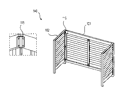
[0030] Fig. 2A illustrates the assembled kit with the reference axes
shown and labeled.
Fig. 2B illustrates a cut away view of the disassembled kit in an open
configuration. Fig. 2C
illustrates a cut away view of the disassembled unit in a closed
configuration.
[0031] Fig. 3A illustrates a support plate attached to a lower portion of
the side panel
that supports a base panel. Fig. 3B illustrates the configuration of the unit
upon placement of
the base panel.
[0032] Fig. 4 illustrates the position of the fasteners that reversibly
join the side panels
to the base panel.
[0033] Fig. 5 illustrates the position of the top panel prior to its
placement onto the top
surface of the side panels and back panel.
[0034] Fig. 6 illustrates the position of the fasteners that reversibly
join the side panels
to the top panel.
[0035] Fig. 7 provides examples of various embodiments of fasteners.
[0036] Fig. 8 illustrates one embodiment in which shelves divide the
space of the
enclosure formed by the top panel, base panel, and side panels.
[0037] Fig. 9 illustrates one embodiment in which one door panel, when
closed, seals
all or a portion of the case storage volume formed by the top panel, base
panel, and side panels.
[0038] Fig. 10 illustrates a view of the kit in which all components are
disassembled.
[0039] Fig. 11 illustrates a flow chart outlining the steps of the method
of assembly.
[0040] Fig. 12 illustrates a flow chart outlining the steps of the method
of manufacture.
DESCRIPTION
[0041] The following description includes various embodiments and method
of
carrying out exemplary embodiments of the present approach. The description is
not to be
-9-
CA 2990552 2017-12-28
taken in a limiting sense, and is made merely for the purpose of illustrating
the general
principles of the present approach.
[0042] The present invention overcomes the limitations of the
conventional furniture
kits that are illustrated in Fig. 1A-C.
[0043] Fig. 2 demonstrates certain advantages of the present approach.
Fig. 2A
illustrates an embodiment of an assembled kit 140 with the reference axes
shown and labeled.
Fig. 2B illustrates a cut away view of the kit 140 in an open configuration.
In one embodiment,
the back panel 101 and side panels 102 are joined by one or more folding
hinges 115. In the
open configuration of this embodiment, the side panels 102 are at right angles
to the back panel
101 and are substantially parallel to each other. Fig. 2C illustrates a cut
away view of the kit
140 in a closed configuration. In this embodiment, the side panels 102 are
folded in and are
substantially parallel to the back panel 101. Fig. 2C is typical of the
embodiment that would be
shipped to the consumer, and Fig. 2B is typical of the embodiment that the
consumer would
make by unfolding the side panels 102 away from the back panel 101. A consumer
needs to
merely swing open the side panels 102 such that they are at right angles to
the back panel 101
and are substantially parallel to each other. No tools are needed, and little,
if any, know-how is
needed, as the side panels 102 can only swing in one direction, away from the
back panel 101.
[0044] Figs. 3A and 3B demonstrate the ease of the base panel assembly.
Fig. 3A
illustrates an upwardly facing support face defined by at least one rigid
support plate 116
affixed to a lower portion of the side panel 102 that supports a base panel
103 at the base of the
two side panels 102. The base portions of the side panels 102 face the back
panel 101 when in a
closed position and the at least one rigid support plate 116 extends along an
x-z plane when the
side panels 102 are in the open position. The at least one rigid support plate
116 may be
-10-
CA 2990552 2017-12-28
attached in any manner of ways known in the art. In one embodiment, the at
least one rigid
support plate 116 may be welded to the lower portion of the side panel 102 by
the
manufacturer. In one embodiment, the at least one rigid support plate 116 is
removably affixed
to the side panel 102. Fig. 3B illustrates the configuration of the unit upon
placement of the
base panel 103 onto the one or more rigid support plates 116. A consumer needs
to merely
place the base panel 103 onto the support plates 116 that are attached to the
side panels 102. No
tools and little, if any, know-how is needed.
[0045] Fig. 4 demonstrates an approach by which the unit of furniture is
made stable
and yet can be assembled and disassembled in a quick and easy manner. Fig. 4
shows a cut
away view of an embodiment of the unit and illustrates a configuration
positioning a plurality
of pre-installed flexible fasteners 117 that join the side panels 102 with the
base panel 103. The
flexible fasteners 117 may be installed in any manner of ways known in the
art. The fasteners
117 lock the side panels 102 with the base panel 103 at right angles. A toggle
portion 131 of
each fastener 117 may be mounted to the side panel 102 and a hook or toggle
receptacle portion
132 of each fastener is mounted to a bottom portion of the base panel 103. The
toggle portion
131 reversibly attaches to the toggle receptacle 132 to lock the side panels
102 to the base panel
103 and restrict the side panels 102 from z-axis rotation and restrict the
base panel 103 from y-
axis rotation. The toggle portion 131 and toggle receptacle 132 may be mounted
to the side
panels 102 and base panel 103 by the manufacturer. The consumer merely needs
to lock the
corresponding toggle portion 131 and toggle receptacle 132 of the fastener 109
together to
create a resilient, stabilized unit.
[0046] Fig. 5 illustrates the position of the top panel 104 onto the top
surface of the side
panels 102 and back panel 101. The top panel 104 is shown connected to the
side panels 102
-11-
CA 2990552 2017-12-28
and back panel 101 by a plurality of position members 118 mounted to a top
edge of the side
panels 102 and a bottom surface of the top panel 104, with the position
members 118 oriented
along the y-axis. The position members 118 are shown in the figures as pins,
but other
embodiments of position members, such as biscuits, dowels, and splines may be
acceptable
alternatives, depending on the application and type of furniture. The position
members 118 fit
into corresponding position member receptacles 119 on the opposite surface.
The position
members 118 restrict the top panel 108 from x and z axis movement. For this
embodiment, a
consumer need merely place the top panel 104 onto the top surface of the side
panels 102 and
back panel 101, aligning the position members 118 with the position member
receptacles 119,
to assemble the top panel 104.
[0047] Fig. 6 illustrates the fasteners 117 that may be used to join the
side panels 102 to
the top panel 104. In one embodiment, a toggle portion 131 of each fastener
117 may be
mounted to the side panel 102 and a toggle receptacle or hook portion 132 of
each fastener may
be mounted to a bottom portion of the top panel 104. In another embodiment, a
toggle portion
131 of each fastener 117 may be mounted to a bottom portion of the top panel
104 and a toggle
receptacle or hook portion 132 may be mounted to the side panel 102. The
toggle portion 131
reversibly attaches to the toggle receptacle or hook portion 132 to release-
ably lock the side
panels 102 to the top panel. Once fastened, the fasteners restrict the side
panels 102 from z-axis
rotation and restrict the top panel 104 from y-axis rotation. The consumer
merely needs to latch
the toggle portion 131 to the toggle receptacle portion 132 to complete this
portion of the
assembly and create a resilient, stabilized unit.
[0048] Fig. 7 illustrates various embodiments of the flexible hook and
toggle fasteners
117. The fasteners 117 may include a toggle portion 131 that is spring loaded
133, which
-12-
CA 2990552 2017-12-28
provides constant tension for secure latching. A spring loaded toggle latch
133 makes the unit
resilient upon loading and unloading due to its flexibility in range of
motion. "Resilient" may
be defined as fastening that permits a minor deformation at the joint, with
the ability to return
to shape after loading, but not so rigid as to damage the surrounding
furniture material to which
the fastener is mounted, as might occur with a glued or otherwise rigid joint
of MDF, for
example. "Deformation" in this context involves both extension and compression
along the
axis of any spring within fastener 117, but also rotation of the latching ring
142 about its mount
on toggle portion 131 or about its connection point on toggle receptacle
portion 132. Thus, the
degree of resilience desired is a function of the specifications of any
springs, as well as the
relation of latching ring 142 to its mount or connection point design.
[0049] Optionally, one or more shelves 105 may be included to divide the
case storage
volume formed by the top panel 104, base panel 103, and side panels 102, as is
shown in Fig. 8.
The one or more shelves 105 are generally attached to the inside portion of
the side panels 102
such that the shelves 105 extend along an x-z plane and are positioned between
the side panels
102. The one or more shelves 105 can be attached in any manner of ways known
in the art.
[0050] Optionally, one or more door panels 106 may be included to seal
off all or a
portion of the case storage volume formed by the top panel 104, the base panel
103, and the
side panels 102, as is shown in Fig. 9. The one or more door panels 106 can be
attached in any
manner of ways known in the art. Fig. 9 shows one embodiment in which one door
panel 106
closes off the space of the enclosure.
[0051] Fig. 10 illustrates a view of the kit with all of the components
disassembled. A
consumer may receive this arrangement in a shipped kit.
-13-
CA 2990552 2017-12-28
. .
[0052] Fig. 11 illustrates a flow chart outline of the steps of the
method of assembly.
These steps illustrate the information that may be found on a kit assembly
instruction page or
manual. In the first step, a consumer unfolds the side panels 102 away from
the back panel 101
such that the side panels 102 are substantially parallel to each other and are
at right angles to
the back panel 101. In the next step, the consumer attaches the base panel 103
by positioning
the base panel 103 onto the one or more rigid support plates 116 between the
side panels 102.
In the next step, the consumer attaches the top panel 104 by aligning position
members 118
with position member receptacles 119 in the side panels 102 and top panel 104.
Next, the
consumer connects the complimentary flexible fastener 117 components to lock
the side panels
102 to the base panel 103 and to lock the side panels 102 to the top panel
104. Optionally, the
consumer may attach one or more shelves 105 to the inside portion of the side
panels 102.
Optionally, the consumer may attach one or more door panels 106 to a front
portion of the side
panels 102.
Fig. 12 illustrates a flow chart outline of the steps of a process or method
for manufacturing the
kit 140 that, when assembled, forms a unit of furniture. In the first step, a
manufacturer
provides 201 a back panel 101, top panel 104, base panel 103, and two side
panels 102 that,
when assembled, form a case defining a storage volume. In the next step, the
side panels 102
are attached 202 to opposite ends of the back panel 101 by a plurality of
folding hinges 115
mounted along the sides of the side panels 102. In the next step, at least one
rigid support plate
116 is provided 203 which can be installed into a lower portion of the side
panels 102. In the
next step, a manufacturer provides 204 a plurality of position members 118
which may be
reversibly installed into a plurality of position member receptacles 119
defined by the top
surface of the side panels 102 and back panel 101. In the next step, a
manufacturer installs 205
-14-
CA 2990552 2017-12-28
a plurality of flexible fasteners 117, wherein the flexible fasteners 117 are
configured such that
when the base panel 103 is placed over the tops of the one or more rigid
support plates 116 and
the top panel 104 is placed over the tops of the side panels 102 and back
panel 101, the toggle
portion 131 and hook portion 132 of the flexible fasteners 117 are capable of
alignment so as to
lock the base panel 103 to the side panels 102 and to lock the top panel 104
to the side panels
102. Optionally, a manufacturer may provide 210 one or more shelves 105 that
may be attached
to an inside portion of the two side panels 102. Optionally, in a manufacturer
may provide 220
one or more door panels 106 that may be pivotally attached to a front portion
of the side panels
102. Further, a manufacturer may provide such alternative embodiments of kit
140 described
herein.
[0053] The terminology used herein is for the purpose of describing
particular
embodiments only and is not intended to be limiting of the approach. As used
herein, the
singular forms "a," "an," and "the" are intended to include the plural forms
as well, unless the
context clearly indicates otherwise. It will be further understood that the
terms "comprises"
and/or "comprising," when used in this specification, specify the presence of
stated features,
integers, steps, operations, elements, and/or components, but do not preclude
the presence or
addition of one or more other features, integers, steps, operations, elements,
components,
and/or groups thereof.
[0054] The present approach may be embodied in other specific forms
without
departing from the spirit or essential characteristics thereof The disclosed
embodiments are
therefore to be considered in all respects as illustrative and not
restrictive, the scope of the
present approach being indicated by the claims of the application rather than
by the foregoing
description, and all changes which come within the meaning and range of
equivalency of the
-15-
CA 2990552 2017-12-28
claims are therefore intended to be embraced therein. One of ordinary skill in
the art should
appreciate that numerous possibilities are available, and that the scope of
the present approach
is not limited by the embodiments described herein.
- 1 6-
CA 2990552 2017-12-28