Note: Descriptions are shown in the official language in which they were submitted.
CA 02991133 2017-12-29
WO 2016/205173 PCT/US2016/037325
AIR FILTER FOR INK JET PRINTER
BACKGROUND
[0001] The present invention relates to ink jet printing and more
particularly to
an apparatus and filter unit for use in ink jet printing, such as, for example
continuous ink jet printing.
[0002] In ink jet printing systems the print is made up of individual
droplets of
ink generated at a nozzle and propelled towards a substrate. There are two
principal
systems: drop on demand where ink droplets for printing are generated as and
when
required; and continuous ink jet printing in which droplets are continuously
produced
and only selected ones are directed towards the substrate, the others being
recirculated to an ink supply.
[0003] Continuous ink jet printers supply pressurized ink to a print
head drop
generator where a continuous stream of ink emanating from a nozzle is broken
up
into individual regular drops by, for example, an oscillating piezoelectric
element.
The drops are directed past a charge electrode where they are selectively and
separately given a predetermined charge before passing through a transverse
electric
field provided across a pair of deflection plates. Each charged drop is
deflected by
the field by an amount that is dependent on its charge magnitude before
impinging
on the substrate whereas the uncharged drops proceed without deflection and
are
collected at a gutter from where they are recirculated to the ink supply for
reuse. The
charged drops bypass the gutter and hit the substrate at a position determined
by the
charge on the drop and the position of the substrate relative to the print
head.
Typically the substrate is moved relative to the print head in one direction
and the
drops are deflected in a direction generally perpendicular thereto, although
the
deflection plates may be oriented at an inclination to the perpendicular to
compensate
for the speed of the substrate (the movement of the substrate relative to the
print head
between drops arriving means that a line of drops would otherwise not quite
extend
perpendicularly to the direction of movement of the substrate).
[0004] In continuous ink jet printing a character is printed from a
matrix
including a regular array of potential drop positions. Each matrix includes a
plurality
of columns (strokes), each being defined by a line including a plurality of
potential
1
CA 02991133 2017-12-29
WO 2016/205173 PCT/US2016/037325
drop positions (e.g. seven) determined by the charge applied to the drops.
Thus each
usable drop is charged according to its intended position in the stroke. If a
particular
drop is not to be used then the drop is not charged and it is captured at the
gutter for
recirculation. This cycle repeats for all strokes in a matrix and then starts
again for
the next character matrix.
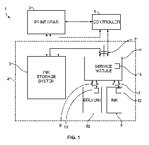
[0005] Ink is delivered under pressure to the print head by an ink
supply system
that is generally housed within a sealed compartment of a cabinet that
includes a
separate compartment for control circuitry and a user interface panel. The
system
includes a main pump that draws the ink from a reservoir or tank via a filter
and
delivers it under pressure to the print head. As ink is consumed the reservoir
is
refilled as necessary from a replaceable ink cartridge that is releasably
connected to
the reservoir by a supply conduit. The ink is fed from the reservoir via a
flexible
delivery conduit to the print head. The unused ink drops captured by the
gutter are
recirculated to the reservoir via a return conduit by a pump. The flow of ink
in each
of the conduits is generally controlled by solenoid valves and/or other like
components.
[0006] As the ink circulates through the system, there is a tendency for
it to
thicken as a result of solvent evaporation, particularly in relation to the
recirculated
ink that has been exposed to air in its passage between the nozzle and the
gutter. To
compensate for this, "make-up" solvent is added to the ink as required from a
replaceable ink cartridge so as to maintain the ink viscosity within desired
limits.
This solvent may also be used for flushing components of the print head, such
as the
nozzle and the gutter, in a cleaning cycle.
[0007] The use of solvents within the printing system may result in
solvent vapor
leaking within enclosed spaces which could result in elevated solvent vapor
levels. It
is known to provide purging air circulation within printing systems to carry
away any
solvent vapor before it can reach harmful or dangerous levels. Additionally,
various
components such as pumps and motors generate heat the can increase the
temperature of the ink within the system. As the ink temperature increases,
the
tendency for solvents to volatilize also increases. Further, increased
temperature also
changes the viscosity of the ink, which must be controlled to within desired
ranges to
achieve optimal printing performance.
2
CA 02991133 2017-12-29
WO 2016/205173
PCT/US2016/037325
[0008] It is an object of the present invention, amongst others, to
provide an
improved or an alternative ink jet printer. Further, the present invention
provides an
ink jet printer with an improved air circulation and cooling system.
BRIEF SUMMARY
[0009] According to a first aspect of the present invention there is
provided an
apparatus for use in continuous inkjet printing, including: a cabinet, an ink
system
located in the cabinet, the ink system including, an ink pump, an ink system
air inlet,
and an ink system air outlet, and an air circulation device arranged to cause
air to
flow within the cabinet. The air circulation device is arranged to cause air
to flow
along a predetermined air flow path through the ink system air inlet, past the
ink
pump, and through the ink system air outlet.
[0010] The provision of an air circulation device allows an air flow to
be used
both for purging solvent vapor from within the cabinet, and also to provide
cooling
for the ink pump given that the predetermined flow path goes past the ink
pump. The
cooling of the ink pump also allows heat from the ink itself to be dissipated.
Thus
heat from the ink is dissipated via the ink pump without the need for a
dedicated ink
cooling apparatus.
[0011] Air flow along the predetermined air flow path may cool the ink
pump
and thereby cool ink passing through the ink pump.
[0012] The apparatus may further include an air filter unit being
arranged to
receive an air filter, the air filter unit including a filter unit air inlet,
and a filter unit
air outlet; wherein, in use, the filter unit air outlet is arranged adjacent
the ink system
air inlet; and the air circulation device is arranged to cause air to flow
through the
filter unit air inlet, the air filter, the filter unit air outlet, and along
the predetermined
path.
[0013] The provision of an air filter unit to direct air flow through
the apparatus
according to a predetermined air flow path allows the air flow to be
controlled for
both for purging and cooling purposes. Further, the provision of an air filter
unit
allows simple replacement or cleaning of an air filter to be carried out at
convenient
intervals without the need to specialist tools or expertise.
3
CA 02991133 2017-12-29
WO 2016/205173
PCT/US2016/037325
[0014] The apparatus may be described as an ink delivery system. The ink
system may be described as an ink storage system.
[0015] The air filter unit may be removable from the apparatus.
[0016] The filter unit air inlet may be arranged to mate with an air
inlet of the
housing.
[0017] The filter unit air outlet may be arranged to mate with the ink
system
air inlet.
[0018] A seal may be formed between the filter unit air outlet and the
ink system
air inlet.
[0019] The filter unit may include a seal member arranged to engage with
an
outer surface of the ink system air inlet to form the seal.
[0020] The air circulation device may be provided in the air flow path
intermediate the ink system air inlet and the ink system air outlet.
[0021] The air circulation device may be provided in the air flow path
intermediate the ink system air inlet and the ink pump.
[0022] The ink pump may be proximal to the ink system air inlet.
[0023] The ink system may further include an ink pump heat sink in
thermal
communication with the ink pump, the air circulation device being arranged to
cause
air to flow past the ink pump heat sink.
[0024] By thermal communication it is meant that thermal energy is able
to flow
between the ink pump and the ink pump heat sink, i.e. that there is a path for
thermal
conduction between the ink pump and the ink pump heat sink.
[0025] The ink system may further include a condenser for condensing
solvent
vapor, and a condenser heat sink in thermal communication with the condenser,
the
air circulation device being arranged to cause air to flow past the condenser
heat
sink.
[0026] The air circulation device may be provided adjacent to the ink
pump.
[0027] The air circulation device may, for example, be a component of
the ink
system.
[0028] The air circulation device may include a fan.
4
CA 02991133 2017-12-29
WO 2016/205173 PCT/US2016/037325
[0029] The cabinet may include a base, and an air outlet may be provided
at the
base of the cabinet, the air circulation device causing air to flow along the
predetermined path and through the air outlet.
[0030] The cabinet may include a door, the air filter unit being
received within
the door.
[0031] The location of the air filter unit within the door provides a
convenient
and accessible location of the air filter unit, which also allows both the
interior of the
cabinet to be accessed (without being impeded by the air filter unit) and the
air filter
unit itself to be accessed for routine and preventative maintenance.
[0032] The air filter unit may be removably received within the door.
[0033] The door may include an air inlet, the filter unit air inlet
being arranged to
mate with the air inlet when the air filter unit is received within the door.
[0034] The mating of the air filter unit with the air inlet within the
door provides
a simple and convenient air flow path into the cabinet.
[0035] The door may be moveable between an open position and a closed
position and when in the closed position the filter unit air outlet may be
arranged
adjacent the ink system air inlet.
[0036] The air filter unit may be removable from the door when the door
is in the
open position.
[0037] When the door is in the closed position a seal may be formed
between the
filter unit air outlet and the ink system air inlet.
[0038] The filter unit air inlet may be provided at a lower end of the
door when
the door is in the closed position.
[0039] The ink system may further include an ink tank for storing ink
for use
during printing operations.
[0040] The air filter unit may include an inlet labyrinth arranged to
obstruct a
direct path between the filter unit air inlet and the air filter. The inlet
labyrinth may
include an inlet baffle.
[0041] The air filter unit may include a body, the filter unit air inlet
and filter
unit air outlet being defined by said body.
[0042] The body may further define a recess for receiving the air
filter.
CA 02991133 2017-12-29
WO 2016/205173 PCT/US2016/037325
[0043] The filter unit air inlet may be defined in a first side of the
body and
the filter unit air outlet may be defined in a second side of the body, the
first and
second sides being generally perpendicular.
[0044] The body may be formed of two components which are hinged
together.
[0045] The air filter maybe removable from the recess by opening the two
components.
[0046]
[0047] According to a second aspect of the invention there is provided a
filter
unit for a continuous inkjet printer including: a body, a filter unit air
inlet defined by
the body and arranged to mate with an air inlet of an ink jet printer cabinet,
a recess
for receiving an air filter defined by the body, a filter unit air outlet
defined by the
body and arranged to mate with an air inlet of an ink system located in an ink
jet
printer cabinet.
[0048] The air inlet may be defined in a first side of the body and the
outlet in a
second side of the body, the first and second sides being generally
perpendicular.
[0049] The body may be formed of two components which are hinged
together.
[0050] The air filter may be removable from the recess by opening the
two
components.
[0051] The air filter unit may include an inlet labyrinth arranged to
obstruct a
direct path between the filter unit air inlet and the air filter. The inlet
labyrinth may
include an inlet baffle.
[0052] The filter unit air outlet may be configured to form a seal with
an air inlet
of an ink system located in an ink jet printer cabinet.
[0053] The filter unit may include a seal member configured to engage
with an
outer surface of an air inlet of an ink system to form the seal.
[0054] According to a third aspect of the invention there is provided an
apparatus
for use in continuous inkjet printing, including: a cabinet; an ink system
located in
the cabinet, the ink system including, an ink pump; and an air circulation
device
arranged adjacent to the ink pump and arranged to cause air to flow past the
ink
6
CA 02991133 2017-12-29
WO 2016/205173
PCT/US2016/037325
pump. Air flow along the predetermined air flow path cools the ink pump and
thereby cools ink passing through the ink pump.
[0055] The air circulation device may be arranged to cause air to flow
past the
ink pump along a predetermined air flow path.
[0056] The apparatus may include an air filter unit arranged to receive
an air
filter.
[0057] The air circulation device may be arranged to cause air to flow
through
the air filter and past the ink pump along the predetermined air flow path.
[0058] According to a fourth aspect of the invention there is provided a
method
for cooling ink in a continuous ink jet printer, the method including: pumping
ink
using an ink pump; causing air flow over the ink pump using an air circulation
device, wherein the air flow effects cooling of the ink.
[0059] It will be appreciated that features described in the context of
one aspect
of the invention may be used in combination with other aspects of the
invention. In
particular, features described in the context of the first and second aspects
of the
invention may be used in combination with the third and fourth aspects of the
invention.
[0060] Embodiments of the present invention will now be described, by
way of
example, with reference to the accompanying drawings, in which:
BRIEF DESCRIPTION OF THE DRAWINGS
[0061] Figure 1 is a schematic illustration of a continuous ink jet
printer in
accordance with an embodiment of the invention;
[0062] Figure 2 is a schematic representation of the continuous ink jet
printer of
Figure 1;
[0063] Figure 3 is perspective illustration of part of the continuous
ink jet printer
of Figure 1;
[0064] Figure 4 is a schematic illustration of the part of the
continuous ink jet
printer shown in Figure 3;
[0065] Figures 5A-5C are perspective illustrations of a part of the
continuous ink
jet printer of Figure 1;
7
CA 02991133 2017-12-29
WO 2016/205173
PCT/US2016/037325
[0066] Figures 6A-6C are perspective illustrations of parts of the
continuous ink
jet printer of Figure 1;
[0067] Figures 7A-7C are perspective illustrations of parts of the
continuous ink
jet printer of Figure 1; and
[0068] Figure 8 is a perspective cross-sectional illustration of part of
the
continuous ink jet printer of Figure 1.
DETAILED DESCRIPTION
[0069] Figure 1 schematically illustrates an inkjet printer 1. Inkjet
printer 1
includes an ink supply system 2, a print head 3 and a controller 4. The ink
supply
system 2 includes an ink storage system 5 and a service module 6 according to
an
embodiment of the present invention. In Figure 1, fluid flow through the
inkjet
printer is illustrated schematically by solid arrows and control signals are
illustrated
schematically by dashed arrows. The service module 6 is configured for
releasable
engagement with inkjet printer 1 so that the module can be easily removed from
the
inkjet printer 1 for servicing or replacement. The service module 6 is
therefore a
removable module for an inkjet printer.
[0070] The service module 6 includes two cartridge connections for
releasable
engagement with a fluid cartridge. In particular, the service module 6
includes an
ink cartridge connection 7 for releasable engagement with an ink cartridge 8
and a
solvent cartridge connection 9 for releasable engagement with a solvent
cartridge 10.
The service module 6 further includes a printer connection 11 for releasable
engagement with an inkjet printer. In use, the service module 6 forms part of
inkjet
printer 1 and it will be appreciated that in this context in the expression
"for
releasable engagement with an inkjet printer" the term "inkjet printer" is
intended to
mean those parts of the inkjet printer excluding the service module 6.
[0071] The printer connection 11 includes a plurality of fluid ports,
each fluid
port arranged to connect to a fluid pathway within the inkjet printer 1 to
allow fluid
to flow between the service module 6 and other parts of the inkjet printer 1,
such as
the ink storage system 5 and the print head 3. The printer connection 11
further
includes an electrical connector arranged to engage with a corresponding
connector
on the inkjet printer 1.
8
CA 02991133 2017-12-29
WO 2016/205173 PCT/US2016/037325
[0072] Each of the ink and solvent cartridge connections 7, 9 includes a
fluid
connector for engaging an outlet of respective ink and solvent cartridges 8,
10 so as
to allow fluid to flow from the cartridges 8, 10 into the service module 6.
From the
service module 6, ink and solvent can flow to the ink storage system 5 via the
printer
connection 11. In operation, ink from the ink cartridge 8 and solvent from the
solvent cartridge 10 can be mixed within the ink storage system 5 so as to
generate
printing ink of a desired viscosity which is suitable for use in printing.
This ink is
supplied to the print head 3 and unused ink is returned from the print head 3
to the
ink storage system 5. The service module 6 is also operable to provide a flow
of
solvent to the print head 3 via printer connection 11 for cleaning purposes.
[0073] The ink jet printer 1 is controlled by controller 4. Controller 4
receives
signals from various sensors within the inkjet printer 1 and is operable to
provide
appropriate control signals to the ink supply system 2 and the print head 3 to
control
the flow of ink and solvent through the inkjet printer 1. The controller 4 may
be any
suitable device known in the art, and typically includes at least a processor
and
memory.
[0074] The ink cartridge 8 may be provided with an electronic data
storage
device 12 storing data relating to contained ink (e.g. type and quantity of
ink).
Similarly, the solvent cartridge 10 may be provided with an electronic data
storage
device 13 storing data relating to contained solvent (e.g. type and quantity
of
solvent). The service module 6 includes an electronic data storage device 14.
Electronic data storage device 14 may store identification data (e.g. an
identification
code). Electronic data storage device 14 may also store other types of data,
such as
identification relating to the type of ink and/or solvent that the service
module 6 can
be used with (or has previously been used with), a model number of the service
module 6 or inkjet printer 1, a serial number, a manufacture date, an
expiration date,
a date first used in service, number of hours the service module 6 has been
used in
the inkjet printer 1, service life, and the like. Information stored on any
one of the
electronic data storage devices 12, 13, 14 may be stored in encrypted form.
This
may prevent any tampering of the data. The electronic data storage device 14
may
include security data so that only suitable or recognized service modules 6
can be
used with the inkjet printer 1. The electronic data storage device 14 may also
include
9
CA 02991133 2017-12-29
WO 2016/205173
PCT/US2016/037325
a writable data portion. The inkjet printer 1 may write to the electronic data
storage
device 14 to indicate that the service module 6 has reached the end of its
service life,
so that the service module can no longer be used in the inkjet printer 1 or
any other
printer.
[0075] The controller 4 is arranged to communicate with the electronic
data
storage devices 12, 13. This communication with the electronic data storage
devices
12, 13 of cartridges 8, 10 is via the service module 6. Each of the ink and
solvent
cartridge connections 7, 9 includes an electrical contact arranged to contact
a
corresponding contact on the engaged ink or solvent cartridge 8, 10. The
corresponding contact on the cartridges 8, 10 allows information to be read
from
and/or written to data storage devices 12, 13 respectively via the printer
connection
11 of the service module 6.
[0076] For example, when the ink supply system 2 is first used, data
from the
electronic data storage device 12 and/or the electronic data storage device 13
is read
to ascertain a type of ink and/or solvent being used. Subsequently, when a new
ink
cartridge or solvent cartridge is used within the printer 1, a check may be
made by
the controller 4 of data stored on respective electronic data storage devices
12, 13 of
the ink cartridge 8 and the solvent cartridge 10 to ensure compatibility. In
this way,
when the ink supply system 2 is used with a particular type of ink, the
controller 4
ensures that the printer 1 is operable (i.e. ensures that ink is allowed to
flow from the
ink cartridge 8 and/or that solvent is allowed to flow from the solvent
cartridge 10)
only if data associated with the ink cartridge 8 and/or solvent cartridge 10
as stored
on the electronic data storage devices 12, 13 indicates compatibility.
[0077] The ink jet printer 1, and particularly the ink supply system 2
is now
described in further detail, with reference to Figure 2. Figure 2
schematically shows
elements of the ink jet printer 1 of Figure 1 in greater detail and, for
clarity, the
controller 4 and associated signals have been omitted.
[0078] In operation, ink is delivered under pressure from ink supply
system 2 to
print head 3 and back via flexible tubes which are bundled together with other
fluid
tubes and electrical wires (not shown) into what is referred to in the art as
an
"umbilical" conduit 15. The ink supply system 2 is located in a cabinet 16
which is
typically stand mounted and the print head 3 is disposed outside of the
cabinet 16.
CA 02991133 2017-12-29
WO 2016/205173 PCT/US2016/037325
[0079] The ink storage system 5 includes a mixer tank 17 for storage of
a
reservoir of ink 18 and a solvent tank 19 for storage of a reservoir of
solvent 20. The
mixer tank has a generally tapered lower portion within which the reservoir of
ink 18
is disposed.
[0080] In operation, ink is drawn from the reservoir of ink 18 in mixer
tank 17 by
a system pump 21. The mixer tank 17 is topped up as necessary with ink and
make-
up solvent from replaceable ink and solvent cartridges 8, 10. Ink and solvent
are
transferred from the ink and solvent cartridges 8, 10 to the mixer tank 17 via
the
service module 6 as will be described further below.
[0081] It will be understood from the description that follows that the
ink supply
system 2 and the print head 3 include a number of flow control valves which
are of
the same general type: a dual coil solenoid-operated two-way flow control
valve.
The operation of each of the valves is governed by the controller 4.
[0082] Ink drawn from the mixer tank 17 is filtered first by a first
(relatively
coarse) filter 22 downstream of the system pump 21 and then is delivered
selectively
under pressure to two venturi pumps 23, 24 and a filter module 25. Filter
module 25
includes a second, finer ink filter 26 and a fluid damper 27. Fluid damper 27
is of
conventional configuration and removes pressure pulsations caused by the
operation
of the system pump 21. Ink is supplied through a feed line 28 to the print
head 3 via
a pressure transducer 29.
[0083] At the print head 3 the ink from the feed line 28 is supplied to
a drop
generator 30 via a first flow control valve 31. The drop generator 30 includes
a
nozzle 32 from which the pressurized ink is discharged and a piezoelectric
oscillator
(not shown) which creates pressure perturbations in the ink flow at a
predetermined
frequency and amplitude so as break up the ink stream into drops 33 of a
regular size
and spacing. The break up point is downstream of the nozzle 32 and generally
coincides with a charge electrode 34 where a predetermined charge is applied
to each
drop 33. This charge determines the degree of deflection of the drop 33 as it
passes a
pair of deflection plates 35 between which a substantially constant electric
field is
maintained. Uncharged drops pass substantially undeflected to a gutter 36 from
where they are recycled to the ink supply system 2 through return line 37 via
a
second flow control valve 38. Charged drops are projected towards a substrate
(not
11
CA 02991133 2017-12-29
WO 2016/205173 PCT/US2016/037325
shown) that moves past the print head 3. The position at which each drop 33
impinges on the substrate is determined by the amount of deflection of the
drop and
the speed of movement of the substrate.
[0084] To ensure effective operation of the drop generator 30 the
temperature of
the ink entering the print head 3 may be maintained at a desired level by a
heater (not
shown) before it passes to the first control valve 31. In instances where the
printer is
started up from rest it is desirable to allow ink to bleed through the nozzle
32 without
being projected toward the gutter 36 or substrate. In such instances ink flows
from
the first control valve 31 to the nozzle 32 and then returns to the second
control valve
38 via a bleed line 39, where it joins return line 37. The passage of the ink
into the
return line 37, whether it is the bleed flow or recycled unused ink captured
by the
gutter 36, is controlled by the second flow control valve 38. The returning
ink is
drawn back to the mixer tank 17 by venturi pump 23.
[0085] Venturi pumps 23, 24 are of known configuration and make use of
the
Bernoulli Principle whereby fluid flowing through a restriction in a conduit
increases
to a high velocity jet at the restriction and creates a low pressure area. If
a side port
is provided at the restriction this low pressure can be used to draw in and
entrain a
second fluid in a conduit connected to the side port. In this instance, the
pressurized
ink flows through a pair of conduits 40, 41 and back to the reservoir 18 in
the mixer
tank 17. Each conduit 40, 41 is provided with a side port 42, 43 at the
venturi
restriction. The increase in flow velocity of the ink creates a suction
pressure at the
side port 42, 43 and this serves to draw returning ink and/or solvent through
return
line 37 and a supply line 44 respectively.
[0086] As ink flows through the system and comes into contact with air
in the
mixer tank 17 and at the print head 3, a portion of its solvent content tends
to
evaporate. The ink supply system 2 is therefore operable to supply make-up
solvent
as required so as to maintain the viscosity of the ink within a predefined
range
suitable for use.
[0087] The service module 6 includes a body 45 defining a plurality of
fluid
conduits (shown schematically in Figure 2 as lines 46). The service module 6
further
includes a flush pump 47 and four valves 48, 49, 50, 51 which are arranged to
selectively link two or more of the plurality of fluid conduits 46 so as to
form one or
12
CA 02991133 2017-12-29
WO 2016/205173
PCT/US2016/037325
more fluid pathways through the body 45. The flush pump 47 and the valves 48,
49,
50, 51 are controlled by the controller 4 by sending one or more control
signals via
the printer connection 11. Using appropriate control signals, the service
module 6
can be disposed in a plurality of different configurations to allow ink or
solvent to
flow through the inkjet printer 1 in a plurality of different modes, as now
described.
In the following, it should be assumed that each of the four valves 48, 49,
50, 51 is
closed unless stated otherwise.
[0088] In operation, ink from the ink cartridge 8 and solvent from the
solvent
cartridge 10 can be added to the mixer tank 17 as required so as to generate
printing
ink of a desired viscosity which is suitable for printing. This addition of
ink and/or
solvent to the mixer tank 17 uses venturi pump 24.
[0089] Mixer tank 17 is provided with a level sensor (not shown) that is
operable
to determine a level of ink in the mixer tank 17 and output a signal
indicative thereof
to controller 4. Ink is consumed during printing and therefore during normal
operation the level of ink in the mixer tank 17 will fall over time. When the
level of
ink in the mixer tank falls below a lower threshold the controller 4 is
operable to
control the ink supply system 2 so as to add more ink to the mixer tank 17.
Using
suitable control signals, ink is drawn from the mixer tank 17 by system pump
21 and
delivered under pressure to venturi pump 24 to create suction pressure at the
side
port 43. To add ink to the mixer tank 17, valves 50, 51 in the service module
6 are
opened. Ink is drawn from ink cartridge 8 along supply line 44 under suction
pressure from venturi pump 24. The ink discharges into the mixer tank 17,
increasing the level. When the level of ink in the mixer tank 17 reaches an
upper
threshold the controller 4 is operable to stop the supply of ink to mixer tank
17. To
achieve this, flow to venturi pump 24 is stopped and valves 50, 51 are closed.
[0090] Following such a process of topping up the level of ink in mixer
tank 17,
the controller 4 sends a signal to data storage device 12 on ink cartridge 8
indicative
of the quantity of ink that has been transferred from the cartridge 8 to the
mixer tank
17. A quantity of ink remaining in the ink cartridge 8 may be stored on the
data
storage device 12 and may be updated in response to the signal from the
controller 4.
[0091] As explained above, as ink flows through the system and comes
into
contact with air in the mixer tank 17 and that the print head 3, a portion of
its solvent
13
CA 02991133 2017-12-29
WO 2016/205173
PCT/US2016/037325
content tends to evaporate. Periodically, the viscosity of the ink within the
mixer
tank 17 (or a quantity indicative thereof) is determined using a viscometer 52
disposed in mixer tank 17.
[0092] The viscometer 52 is periodically supplied with ink under
pressure from
system pump 21 via filter module 25. Flow of ink into the viscometer is
controlled
by control valve 53. Using control valve 53, a predetermined volume of ink is
supplied to a chamber within viscometer 52 and then supply of ink to the
viscometer
is stopped. Ink then drains out of the chamber under gravity. The rate at
which the
ink drains out of the chamber is dependent on the viscosity of the ink and is
monitored using a plurality of electrodes disposed at different levels within
the
chamber. Signals from the plurality of electrodes are received by controller
4, which
is operable to determine whether or not the viscosity of ink within the mixer
tank 17
is within a desired operating range, defined by lower and upper threshold
values.
[0093] If the viscosity is above the upper threshold value then solvent
is added to
the mixer tank 17 from solvent reservoir 20 in solvent tank 19 as now
described. Ink
is drawn from the mixer tank 17 and delivered under pressure to venturi pump
24 to
create suction pressure at the side port 43. To add solvent, valves 49, 50 in
the
service module 6 are opened. Under suction pressure from the venturi pump 24,
solvent is drawn from solvent reservoir 20 along line 62 to the service module
6 and
back along supply line 44 to the mixer tank 17. The solvent discharges into
the
mixer tank 17, reducing the viscosity of the ink in reservoir 18.
[0094] The controller 4 may determine a quantity of solvent to add to
the mixer
tank 17 based on the determined viscosity of the ink. When a desired quantity
of
solvent has been added to the mixer tank 17, flow to the venturi pump 24 may
be
stopped and the valves 49, 50 are closed.
[0095] Once solvent has been added to the mixer tank 17, the viscometer
52 may
be used again to determine the viscosity of ink. There may be a time delay
between
adding the solvent and re-checking the viscosity of the ink so as to allow the
solvent
to mix with ink. If upon re-checking the viscosity of the ink in mixer tank 17
the
viscosity is still above the upper threshold value then more solvent may be
added to
the mixer tank 17 from solvent reservoir 20 in solvent tank 19. This process
may be
repeated until a desired viscosity of ink in mixer tank 17 is reached.
14
CA 02991133 2017-12-29
WO 2016/205173 PCT/US2016/037325
[0096] Solvent tank 19 is provided with a level sensor (not shown) that
is
operable to determine a level of solvent in the solvent tank 19 and output a
signal
indicative thereof to controller 4. Solvent is consumed during operation of
the
printer 1 as it is added to the mixer tank 17 to adjust the viscosity of the
ink in
reservoir 18. Therefore the level of solvent in the solvent reservoir 20 in
solvent tank
19 falls over time.
[0097] When the level of solvent in the solvent tank 19 falls below a
lower
threshold, the controller 4 is operable to control the ink supply system 2 so
as to add
more solvent to the solvent tank 19. Using suitable control signals, valves
48, 49 in
the service module 6 are opened. Solvent is drawn from solvent cartridge 10 by
electric flush pump 47 in the service module 6 and is supplied through line 62
to the
solvent reservoir 20. The solvent discharges into the solvent reservoir 20,
increasing
the level.
[0098] When the level of solvent in the solvent tank 19 reaches an upper
threshold the controller 4 is operable to stop the supply of solvent to
solvent tank 19.
To achieve this, flow to flush pump 47 is stopped and valves 48, 49 are
closed.
[0099] Following such a process of topping up the level of solvent in
solvent
tank 19, the controller 4 sends a signal to data storage device 13 on solvent
cartridge
indicative of the quantity of solvent that has been transferred from the
cartridge
10 to the solvent tank 19. A quantity of solvent remaining in the solvent
cartridge 10
may be stored on the data storage device 13 and may be updated in response to
the
signal from the controller 4.
[00100] Make-up solvent, provided from the solvent cartridge 10, is
also used
to flush the print head 3 at appropriate times to keep it clear of blockages,
as now
described. Ink is drawn from the mixer tank 17 and delivered under pressure to
venturi pump 23 to create a suction pressure at the side port 42. Solvent is
drawn
from solvent cartridge 10 by electric flush pump 47 in the service module 6
and is
supplied through a flush line 54 to the print head 3 via filter 55. Flow of
solvent
from the service module 6 to the print head 3 is controlled by first control
valve 31.
[00101] A pressure relief valve 56 is connected across the inlet and
outlet of the
flush pump 47 and acts to relieve excess pressure to the suction side of the
flush
CA 02991133 2017-12-29
WO 2016/205173
PCT/US2016/037325
pump 56. For example, pressure relieve valve 56 may be arranged to maintain a
desired pressure downstream of the flush pump 47, for example 2.5 bar.
[00102] The solvent flows through the first control valve 31 to the
nozzle 32.
After passing through the nozzle 32 and into the gutter 36 the solvent (along
with
dissolved ink from the print head 3) is drawn into the return 32 under suction
pressure from the venturi pump 23. The solvent and ink discharge into the
mixer
tank 17.
[00103] As explained above, flow of ink and solvent into mixer tank 17
is
achieved using venturi pump 24, which requires a minimum quantity of fluid in
mixer tank 17. If there is insufficient fluid in the mixer tank 17 for
operation of the
venturi pump 24 (e.g. before a first use of the ink supply system 2), the
flush pump
47 in service module 6 can be used to prime the mixer tank 17 by adding fluid
to it.
[00104] To prime the mixer tank 17, an ink cartridge is engaged with
the
solvent cartridge connection 9. To add ink to the mixer tank 17, valves 48, 50
in the
service module 6 are opened. Ink is drawn from an ink cartridge (in the
solvent
cartridge connection 9) by electric flush pump 47 in the service module 6 and
is
supplied through supply line 44 to the mixer tank 17 via side port 42. Once a
sufficient quantity of ink has been added to the mixer tank 17, flush pump 47
is
stopped and valves 48, 50 are closed.
[00105] In use, the atmosphere in the mixer tank 17 and the solvent
tank 19 can
become saturated with solvent. A condenser unit 57 is provided in an upper
portion
of the solvent tank 19. Condenser unit 57 may, for example, include a Peltier-
type
condenser.
[00106] A ventilation tube 58 is provided between the mixer tank 17 and
the
solvent tank 19 to allow air to flow therebetween. The ventilation tube 58 is
arranged such that it links a space above the reservoir of ink 18 to a space
above the
reservoir of solvent 20. Solvent-laden vapor from the mixer tank 17 enters the
solvent tank 19 via ventilation tube 58. The air from the mixer tank 17 is
warmer
than the air in the solvent tank (due to the action of the system pump 21),
and
therefore it rises to the top of the solvent tank via ventilation tube 58,
where it enters
the condenser unit 57.
16
CA 02991133 2017-12-29
WO 2016/205173 PCT/US2016/037325
[00107] Solvent condenses as the air contacts an active element within
the
condenser unit 57 and is cooled. The condensate (solvent) drains into the
solvent
reservoir 20. The dried air (from which the solvent has been removed) enters
the
common port of a three-way control valve 59. The flow of air through the
system
can be controlled using control valve 59, as now described.
[00108] The dried air from the condenser unit 57 may flow through exit
line 60,
via which it is vented to the air space inside the printer cabinet 16. This
air flow path
may be a default configuration for control valve 59.
[00109] Alternatively, the dried air from the condenser unit 57 may
flow
through line 61 which passes through the umbilical 15 to the print head 3.
Line 61
terminates in the print head 3 at return line 37, near the gutter 36. Vacuum
pressure
draws the vented air along the return line 37 towards the second control valve
38
(along with any ink entering the gutter 36). Normal operation of venturi pump
23
draws the unused ink drops and vented air along the return line 37, through
the
umbilical 15 and back to side port 42. The unused ink and vented air are both
discharged into the mixer tank 17.
[00110] When control valve 59 is used to direct the dried air from the
condenser unit 57 through line 61, a 'closed' hydraulic loop is created. Any
solvent
vapor which is not recovered by the condenser unit 57 passes back to the mixer
tank
17 via lines 61, 32 and loss of solvent from the inkjet printer 1 is therefore
minimized. The system recirculates the same air continuously, which prevents
(or at
least minimizes) the influx of ambient air, which would otherwise enter via
the gutter
36 (e.g. if the control valve 59 is venting the dried air from the condenser
unit 57 to
the air space inside the printer cabinet 16 via exit line 60). This preclusion
of
ambient air entering the system helps to prevent oxygen ingestion via the
gutter 36,
which promotes improved ink performance over the long term by reducing the
probability of ink oxidation.
[00111] As will be described in more detail below, in some embodiments,
the
service module 6 further includes a gas sensor, which may be operable to
determine
the presence or level of a gas (such as solvent vapor) within the cabinet 16.
Gas
sensors can become "poisoned" over time and therefore generally have a finite
service lifetime, requiring replacement thereafter.
17
CA 02991133 2017-12-29
WO 2016/205173 PCT/US2016/037325
[00112] The service module 6 provides an interface between the inkjet
printer 1
and each of ink and solvent cartridges 8, 10, allowing fluid to flow from each
of the
cartridges 8, 10 to the inkjet printer and providing an electrical link
between the
inkjet printer 1 and each of the cartridges 8, 10. Since the printer
connection 11
provides for releasable engagement with an inkjet printer the service module 6
can be
easily removed from the inkjet printer 1 for servicing or replacement. In
general,
such servicing or replacement will be performed at a different rate to that of
replacement of the fluid cartridges 8, 10, or the rate of replacement of other
replaceable components of the printer 1. This is advantageous because during
operation of the inkjet printer 1, one or more of the plurality of conduits
46, valves
48, 49, 50, 51 and flush pump 47 may become blocked or damaged, or the gas
sensor
may reach the end of its useful life.
[00113] Referring to Figures 3 to 8, the physical arrangement of the
ink supply
system 2 and associated components are described in more detail. The ink
supply
system 2 includes cabinet or housing16 having a door 65. The cabinet 16
contains
ink supply system components such as, for example, the ink storage system 5,
the
service module 6 and the ink and solvent cartridges 8, 10.
[00114] The ink supply system cabinet 16 includes three generally
vertical side
walls arranged to provide three adjacent sides of the cabinet 16, an aperture
to a
fourth side, a top and a base. The door 65 is pivotally connected to the
cabinet 16
such that the door can be opened by pivoting about a pivot 66 (shown open in
Figure
3). The pivot 66 is provided along an edge the base of the cabinet 16 which is
adjacent to the aperture. The three side walls, the door 65, the top and the
base are
arranged to enclose a volume of space in which the components of the ink
supply
system 2 are housed. When the cabinet 16 is in a normal upright orientation,
with the
door 65 in the closed position, such as during printing operations, the base
of the
cabinet 16 is at the bottom of the cabinet 16 (i.e. it is the lowest part of
the cabinet
16). The pivot 66 is thus provided at the lowest part of the door 65. The door
65 can
be opened so as to access the internal components of the cabinet 16, such as,
for
example, the ink storage system 5, the service module 6 and the ink and
solvent
cartridges 8, 10.
18
CA 02991133 2017-12-29
WO 2016/205173
PCT/US2016/037325
[00115] As best seen in Figure 4, when in the closed position, the door
65
forms a seal with the cabinet 16, such that vapors and liquid do not escape
from
between the cabinet 16 and the door 65. An air inlet 67 is provided at the
bottom of
the door 65 and is arranged such that when the door is in the closed position
the air
inlet 67 is oriented facing vertically downwards. The air inlet 67 allows air
to flow
into the cabinet 16 via the door 65 (even when the door 65 is closed). The
cabinet 16
is also provided with an air outlet 68 which may be provided within the base
of the
cabinet 16 and allows air to flow out of the cabinet 16. The air flow through
the
cabinet 16 is described in more detail below.
[00116] The ink storage system 5 contains the system pump 21, the mixer
tank
17, filter module 25, and other ink storage system components discussed in
more
detail above, and shown schematically in Figure 4. The ink storage system 5
further
includes a fan 69, an air inlet 70 and an air outlet 71. The system pump 21 is
provided with a heat sink 72. The operation of the fan 69, air inlet 70, air
outlet 71
and heat sink 72 are described in more detail below.
[00117] Figure 5A shows the external appearance of the ink storage
system 5,
showing air inlet 70, while Figure 5B shows the external appearance of the ink
storage system 5, showing air outlet 71. Figure 5C shows the ink storage
system 5
with a top cover 5a removed, showing the fan 69, system pump 21, heat sink 72
and
filter module 25.
[00118] The door 65 includes a body portion 73, as shown in Figure 6A,
which
forms part of the exterior of the cabinet 16. The body portion 73 is provided
with a
molded insert 74, as shown in Figure 6B which is received therein. The molded
insert 74 is configured to receive a filter unit 75, which is shown in Figure
6C. The
filter unit 75 can be removed from the door 65 when the door 65 is in the open
position.
[00119] The filter unit 75 is shown in more detail in Figures 7A to 7C.
The
filter unit 75 includes a body having a first housing portion 76 (Figure 7A)
and a
second housing portion 77 (Figure 7B) which may be, for example, plastic
moldings.
The first housing portion 76 and the second housing portion 77 may, for
example, be
assembled to form the filter unit 75 by snap fitting together. The first and
second
19
CA 02991133 2017-12-29
WO 2016/205173 PCT/US2016/037325
housing portions 76, 77 may be hinged together so as to allow the filter unit
75 to be
opened.
[00120] The filter unit further includes a filter unit air inlet 78 and
a filter unit
air outlet 79. The filter unit 75 further includes a recess 80 to receive an
air filter. The
recess is defined by corresponding wall portions provided by the first and
second
housing portions 76, 77. A first wall portion 81 is provided by the first
housing
portion 76, and a second wall portion 82 is provided by the second housing
portion
77. The first wall portion 81 protrudes from an internal surface of the first
housing
portion 76 to define a perimeter of the recess 80. A plurality of apertures 83
are
provided within the first wall portion to allow air to flow into the recess 80
from the
filter unit air inlet 78. The second wall portion 82 is continuous (i.e. it
has no
apertures), and also defines the perimeter of the recess 80. The second wall
portion
82 protrudes from an internal surface of the second housing portion 77.
[00121] In use an air filter 84 is provided within the recess 80. The
filter 84 is
shown located within the recess in Figure 7C. The filter includes a sealing
portion 85
around its perimeter. The sealing portion 85 is arranged to engage with the
second
wall portion 82 when the first and second housing portions 76, 77 are
assembled so
as to form a seal. This seal ensures that there is no direct path for air to
flow from the
inlet 78 to the outlet 79 without passing through the filter 84.
[00122] The sealing portion 85 may, for example, include polyurethane.
The air
filter 84 may include appropriate filter media such as filter paper.
Appropriate filter
paper may have a weight of about 130 g/m2. For example a weight in the range
of
125 to 135 g/m2. The filter paper may have a thickness of greater than or
equal to
0.43 mm, and/or air permeability of greater than or equal to 240
litres/minute. The
paper may have a maximum pore size of less than or equal to 71 p.m, and/or a
minimum pore size of greater than or equal to 61 p.m. The paper may have a
bursting
strength of around 280 kPa, and/or an air flow resistance of less than or
equal to 1.8
mbar and/or a corrugation depth of between 0.1 and 0.25 mm.
[00123] The filter unit 75 further includes an inlet baffle 86. The
inlet baffle 86
protrudes from the internal surface of the first housing portion 76. The
filter unit 75
further includes an outlet grille 87 and an outlet seal 88 (best seen in
Figure 8).
CA 02991133 2017-12-29
WO 2016/205173 PCT/US2016/037325
[00124] In general terms, the filter unit 75 provides an enclosure
which
contains the filter 84, and allows air to be directed along a predetermined
flow path,
as described in more detail below.
[00125] The use of solvents within the printing apparatus may result in
solvent
vapor leaking from the fluid pathways and components within the cabinet 16.
Moreover, the venting of dried air within the cabinet 16 is routine (as
described
above in more detail). This may result in elevated solvent vapor levels within
the
cabinet 16 if the dried air is not entirely free from solvent vapor. It is
desirable,
therefore, to provide air circulation within the cabinet 16 to carry away any
solvent
vapor before it can reach harmful or dangerous levels. Such purging air
circulation is
common place within continuous inkjet printers. However, it has been realized
that
by arranging various components of the printer 1 in a certain way, the purging
airflow can be used to particularly beneficial effect. That is, the airflow
through the
cabinet 16 can be caused to flow through a predetermined flow path P in which
it
performs several useful functions, and also in which components which may be
required to be accessed for preventative maintenance purposes are readily
accessible.
Further, the purging air flow can be used to improve thermal management.
Indeed,
various components within the ink delivery system 2, and in particular the ink
storage system 5, such as pumps (e.g. the system pump 21) and motors generate
heat
the can increase the temperature of the ink within the printer 1. As the ink
temperature increases, the tendency for solvents to volatilize also increases.
Further,
increased temperature also changes the viscosity of the ink, which must be
controlled
to within desired ranges to achieve optimal printing performance.
[00126] The predetermined air flow path P through the cabinet 16 is now
described in detail with reference to Figures 3 to 8. The airflow is caused by
the fan
69, which is located with the ink storage system 5. The fan 69 causes a
negative
pressure to be generated upstream of the fan 69, between the fan 69 and the
air inlet
70. This generated negative pressure causes air to be drawn through the filter
unit 75,
via the door inlet 67, as shown in detail in Figures 4 and 8. Air is initially
drawn into
the door inlet 67, and then (as shown in Figure 8) into the filter unit air
inlet 78. Once
within the filter unit 75 air passes around the inlet baffle 86 and into the
filter recess
21
CA 02991133 2017-12-29
WO 2016/205173 PCT/US2016/037325
80 through the apertures 83. From the cavity 80 air flows through the air
filter 84 and
out of the filter unit outlet 79.
[00127] The inlet baffle 86 obstructs the direct path to the filter
cavity 80 from
the filter unit inlet 78 forming an inlet labyrinth. This ensures that when
the printer 1
is operated in wet environments, such as food production environments which
are
routinely washed-down, water is unlikely to splash directly onto the filter 85
within
the filter cavity 80. Further, the orientation of the filter unit 75 when the
door 65 is
closed is such that the filter unit inlet 78 is provided on a side of the
filter unit 75
which is directed substantially downwards, such that water ingress is
minimized. The
filter unit inlet 78 mates with the air inlet 67 provided within the door 65.
[00128] The outlet seal 88 engages with the air inlet 70 of the ink
storage
system 5 forming an air-tight seal. This seal results in a majority of air
being drawn
into the ink storage system inlet 70 via the air filter unit 75 (i.e. along
the
predetermined air flow path P), and a minimal amount of air being drawn into
the ink
storage system inlet 70 from the interior of the cabinet 16. The filter unit
air outlet 79
is disposed on a side of the filter unit which faces the ink storage system 5.
The filter
unit air outlet 79 is thus a provided on a side of the filter unit 75 which is
substantially perpendicular to the side on which the filter unit air inlet 78
is provided
(the filter unit air inlet 78 being directed substantially downwards).
[00129] Once the air passes the fan 69, it is driven along a path which
passes
over the system pump 21, which is located adjacent to the fan 69. The
proximity of
the fan 69 to the system pump 21 results in a significant cooling effect being
provided to the system pump 21. Additionally, the close proximity of the fan
69 to
the system pump 21 may result in turbulent air from the fan being directed
over the
system pump 21. This turbulence increases the cooling effect of the air flow
on the
system pump 21. Such an effect may also allow the fan 69 to cool the system
pump
21 in the event that the air flow into the cabinet 16 via the filter unit 75
becomes
obstructed. That is, re-circulation of air within the cabinet, and in
particular the
creation of turbulent air-flow around the system pump 21 may cause some heat
to be
transferred away from the system pump 21 (albeit to a lesser extent than when
air is
drawn into the cabinet 16).
22
CA 02991133 2017-12-29
WO 2016/205173 PCT/US2016/037325
[00130] Moreover, the system pump 21 is located close to the ink system
air
inlet 70. Such proximity between the system pump 21 and the air inlet 70
results in
the air which reaches the system pump 21 being as cool as possible. That is,
the
temperature of the air which flows over the system pump 21 has not been raised
by
mixing with warmer air within the ink storage system 5, or by passing over
other
system components which may raise the temperature before it has reached the
system
pump 21.
[00131] It will be appreciated that the system pump 21 may be required
to
operate continuously for extended periods of time. The temperature of the
system
pump 21 may thus become elevated as a result of such continuous operation.
[00132] The flow or air directly over the system pump 21 causes heat to
be
carried away from the pump 21, allowing a safe operating temperature to be
maintained even when the pump 21 is required to operate for extended periods.
This
cooling effect also prevents the ink from exceeding the desired temperature
operating
range, especially when the ambient temperature is high. The pump 21 thus
allows
heat from the ink itself to be dissipated. This provides an additional
advantage in that
heat from the ink is dissipated without the need for a dedicated ink cooling
apparatus.
Moreover, the provision of active cooling of the system pump 21 may allow the
printer 1 to be operated in a wider range of thermal conditions. The range of
ambient
temperatures in which the printer 1 can operate with such cooling may, for
example,
be from 0 to 50 C.
[00133] The system pump 21 is additionally provided with the heat sink
72.
The heat sink 72 may, for example, be formed from a material having a high
thermal
conductivity (e.g. a metal, such as, for example, aluminium). The heat sink 72
is in
thermal communication with the pump 21 such that heat generated within the
pump
is able to flow to the heat sink 72. The heat sink 72 is shaped to have a
large surface
area, for example by being provided with fins, so as to maximize the heat
transferred
away from the system pump 21. The arrangement of the heat sink 72 and directed
air
flow further enhances the ability of the printer 1 to operate across a wide
range of
ambient temperatures and conditions.
23
CA 02991133 2017-12-29
WO 2016/205173
PCT/US2016/037325
[00134] Once the air passes the system pump 21 the air flow path exits
the ink
storage system 5 via the outlet 71, which takes the form of a slotted grille
in the
housing of the ink storage system 5.
[00135] In some embodiments, in addition to the air flow path passing
the
system pump 21 (and heat sink 72), the air flow path may be used to cool other
ink
storage system components. For example, the air flow path may be directed over
electronic components housed within the ink storage system 5 so as to cool
those
electronic components.
[00136] Further, an additional heat sink may be associated with the
condenser
unit 57 (which is best seen in Figure 2). That is, a condenser heat sink may
be in
thermal communication with the condenser unit 57. The air flow caused by the
fan
69 may be caused to flow over the condenser heat sink, providing cooling to
the
condenser unit 57. This provides an additional advantage in that thermal
energy
extracted from solvent-laden vapor during the condensation process is
dissipated as
heat from the condenser unit 57 without the need for a dedicated cooling
apparatus,
such as an additional fan.
[00137] Finally, the air exits the cabinet 16 via the outlet 71 in the
base of the
cabinet 16. The sealed nature of the cabinet 16 (including seal with door 65)
results
in the outlet 71 being the only available exit for air.
[00138] The filter unit 75 may be removed from the ink supply system 2,
and
replaced as necessary. It will be appreciated that such a components may be
required
to be replaced at regular service intervals so as to ensure that the filter 84
remains in
good condition and is not blocked. The filter 84 may be replaced at regular
intervals
such as for example after about 2000 hours of printer operation. Such regular
preventative maintenance may be carried out so as to ensure adequate air
circulation
within the cabinet 16, and in particular to ensure adequate cooling
performance of
the system pump 21 and ink for continued operation. The provision of a
separate and
removable filter unit allows for convenient maintenance by untrained personnel
which minimizes the risk that any critical system components are interfered
with
during maintenance. Further, a removed air filter unit 75 may be replaced with
new
air filter unit, or otherwise re-conditioned by replacement of the filter 84.
The first
and second housing portions 76, 77 may be hinged open so as to access and
replace
24
CA 02991133 2017-12-29
WO 2016/205173 PCT/US2016/037325
the filter 84. Embodiments of the invention thus provide a printing apparatus
which
can be maintained conveniently with minimal risk of error or unnecessary
complication.
[00139] The provision of a filter unit 75 which may be removed and
replaced
as necessary allows any accumulation of unwanted, and possibly unhygienic,
matter
to be prevented, or at least reduced. For example, the filter unit 75 may be
removed
from the cabinet 16 and replaced with a clean filter unit during a cleaning
process.
Alternatively, the filter unit may be arranged so that the filter housing
portions 76
and 77 can be opened by a user and just the filter 84 replaced. Additionally,
a filter
unit may be removed from the cabinet 16, the filter unit 75 opened, and the
air inlet
labyrinth (including inlet baffle 86) cleaned at any convenient interval (e.g.
daily, or
between preparation of two different foods on the production line).
[00140] This may be particularly appropriate where the printer 1 is
used in
hygienic environments such as food production environments. It will be
appreciated
that "a hygienic environment" may include any environment which it is desired
to
keep clean. Such environments include food preparation environments, medical
environments (e.g. for pharmaceutical or medical product manufacture) or the
like.
[00141] It will be appreciated that the air flow path described above
is the
primary air flow path, and that there may be some deviations from this path.
For
example, there may be some leakage of air from the cabinet 16 from access
ports
(e.g. such as access ports provided for conduit 15). Further, seals forms
between the
cabinet 16 and the door 65, and the filter unit outlet 79 and ink storage
system inlet
70 may not be perfect seals. Some air may leak through these seals. Moreover,
rather
than flowing directly from the ink system air outlet 71 to the air outlet 68
the air may
circulate within the cabinet 16 before eventually exiting through the air
outlet 68.
However, a majority of air flow driven by the fan 69 will follow an air flow
path
substantially as described above.
[00142] In the above described embodiment the airflow is driven by the
fan 69
which is located within the ink storage system 5. It will be appreciated,
however, that
the airflow may instead be driven by alternative air circulation devices, such
as, for
example a vacuum pump applied to a vacuum port (which may be provided at the
outlet 68). Alternatively, air may be blown into an air inlet by an externally
provided
CA 02991133 2017-12-29
WO 2016/205173 PCT/US2016/037325
air supply. In a further alternative an air circulation device may be located
at
different locations within or about the cabinet 16. In some embodiments an air
circulation device is located between the filter unit 75 and the ink storage
system 5.
[00143] Further, in some embodiments the air circulation device
includes a
plurality of air circulation devices. For example, in an embodiment a primary
air
circulation device is provided which causes air to flow through the cabinet
16, while
a secondary air circulation device is provided adjacent to the ink pump within
the
cabinet so as to cause air to flow past the ink pump and thus to cause heat to
be
transferred away from the ink pump. In such an embodiment the primary air
circulation device may be provided externally of the cabinet 16.
[00144] It will be appreciated that embodiments of the invention may
deviate
from that which is described above. For example, the provision of first and
second
housing portions 76, 77 of the filter unit 75, having various protrusions
molded
thereon (e.g. baffle 86, first and second walls 81, 82) is simply one
implementation.
Such features may be provided by separate component parts, or by the same
component parts in alternative arrangements. Further an inlet labyrinth
(described
above as including the inlet baffle 86) may be formed in any convenient way so
as to
obstruct the direct path between the filter unit air inlet 78 and the filter
cavity 80.
[00145] Thus, the present system provides an ink jet printer with an
improved
air circulation and cooling system. The system helps to maintain the desired
temperature of the ink within the system to reduce solvent loss and maintain
the ink
viscosity within a desired range.
[00146] The invention is described with reference to the drawings in
which like
elements are referred to by like numerals. The relationship and functioning of
the
various elements of this invention are better understood by the following
detailed
description. However, the embodiments of this invention as described below are
by
way of example only, and the invention is not limited to the embodiments
illustrated
in the drawings.
[00147] The described and illustrated embodiments are to be considered
as
illustrative and not restrictive in character, it being understood that only
the preferred
embodiments have been shown and described and that all changes and
modifications
that come within the scope of the inventions as defined in the claims are
desired to be
26
CA 02991133 2017-12-29
WO 2016/205173 PCT/US2016/037325
protected. It should be understood that while the use of words such as
"preferable",
"preferably", "preferred" or "more preferred" in the description suggest that
a feature
so described may be desirable, it may nevertheless not be necessary and
embodiments lacking such a feature may be contemplated as within the scope of
the
invention as defined in the appended claims. In relation to the claims, it is
intended
that when words such as "a," "an," "at least one," or "at least one portion"
are used
to preface a feature there is no intention to limit the claim to only one such
feature
unless specifically stated to the contrary in the claim. When the language "at
least a
portion" and/or "a portion" is used the item can include a portion and/or the
entire
item unless specifically stated to the contrary.
27