Note: Descriptions are shown in the official language in which they were submitted.
VIBRATING SCREENING FEEDER AND METHOD OF USE
TECHNICAL FIELD
The present invention relates to the field of industrial vibrating screens for
separating
small elements from large elements, such as in the case of CO81 or stone.
BACKGROUND OF THE INVENTION
In the handling of particulate bulk material, there are numerous ways for
conveying such
material and feeding it over an open end of the conveyor to a desired point of
delivery. This
invention is concerned with a conveyor or feeder vibrated as a free mass,
i.e., the trough or
conveyor is suitably isolated from the ground so that it may be vibrated in
response to an
oscillating force, as distinguished from a mass which is positively connected
to the exciting
force, as, for example, by driving the conveyor through an arm rigidly
connected to a fixed stroke
eccentric drive.
Vibrating screens are in use in numerous industrial situations where the
necessary
separation of dust and fine particles of a given product is necessary. For
example, electrical
utility companies burn coal, which must be delivered to the boilers in almost
powdered form and
screening of the coal aggregate is necessary in very great volumes.
Conventional mechanical means operate by varying the frequency or the stroke
of the
= feeder.
1
CA 2991321 2019-08-01
CA 02991321 2018-01-03
WO 2017/007508
PCT/US2016/000056
An exception to mechanical means for adjusting rates of feed is in the case of
an electromagnetic
drive for a feeder, in which case the frequency or the voltage of the applied
pulsating current applied
to the electromagnetic drive is varied. However, in this type of device the
vibrations per minute used
are generally above 1800 cycles per minute and have relatively short strokes
with the result that such
feeders are limited to bulk materials of the more free-flowing type as
distinguished from those which
are characterized as damp or viscous.
Mechanical means such as either a variable rate spring device which may
include an air bag
interposed in the drive with the pressure in the air bag being adjustable to
effect the change of spring
rate, or some form of mechanical adjustment of the drive motors angularity or
position relative to
the pan. There have been many attempts, in vibratory feeders, to utilize some
form of adjustable
feed rate control using electrical phenomena, but to date none of these have
been successful for a
number of reasons. The electromagnetic type vibrators have high energy losses
and are restricted to
essentially high frequency and short stroke combinations. Low frequency, long
stroke devices have
been conceived that utilize adjustable frequency A.C. drives, multi-speed,
and/ or multi-winding
A.C. motors, or adjustable voltage D.C. drives, have met with success because
of high initial cost,
and the cost of maintenance due to brush wear, commutator problems and the
like.
Induced conveying improves material handling in applications where different
kinds of solid
fuels are used to produce heat in a boiler with a vibrating stoker grate that
burns it. The vibratory
feeders and screens induce the fuel's movement instead of forcing it. This
avoids squeezing and
bunching the fuel. The Particles remain loose which facilitates more efficient
burning. Some power
plant boilers are fired by fuels such as coal meeting a demanding
specification wherein the fuel met
the designation of "steam coal" having a particle size, density, and moisture
content specified for
efficient combustion.
When fuel is scarce because of shortages uncleaned ROM coal and the waste
coals such as
culm, gob, silt, or high moisture "wet" coal are burned, especially in
countries having economic
difficulties. The biomass fuels of bagasse, wood waste such as bark, chips,
shavings, and sawdust
2
CA 02991321 2018-01-03
WO 2017/007508
PCT/US2016/000056
fuel is used to fire boilers. Refuse derived fuels- (RDF) which is shredded
municipal waster and
whole or shredded rubber tries can also be sources of fuel. Density and
moisture content are difficult
to control. The induced vertical flow and induced conveyance flow provided by
vibrating feeders,
screens, and conveyors are used because these fuels are usually obstinate to
flow from storage.
Generally, a vibrating screen is fixedly mounted in a screen housing with
supporting frame
work. The screen housing is then supported above a fixed base by springs or
rotatable arms. The
screen housing is caused to vibrate by some sort of drive which shakes the
housing. Some drives
are fixed to the base and connected by a crank journal to the vibrating screen
housing. The prior art
illustration shown in Figure 1 shows a fixed base member 102, a motor and a
crank journal driving
a vibrating screen housing 108 which is movable relative to the fixed base 102
about rotating arms
104 with damper springs 20. Other drives consist of a motor fixed to the
vibrating screen housing
driving eccentric weights which then cause the screen housing to vibrate.
These units have inherent
disadvantages such as difficulty of changing or repairing motor drives and
large energy consumption.
In the vibratory industry, vibratory conveying apparatus such as vibrating
feeders, vibrating
conveyors, vibrating screens, vibrating heat transferring fluidized beds,
attrition mills, and the like,
were all powered by a well-known and popular driving method called the "Single
Input" or ''Brute
Force" type of drive. A single pair of rotating eccentric weights is the sole
source of the input power
in this kind of drive. Being installed directly across from one another, a
single pair of eccentric
weights rotating in opposite directions vibrate the vibratory conveying
apparatus with a linear or
"back and forth", straight line motion. As the load carrying capability of the
conveying apparatus
increased over the years, the weight of the rotating eccentric weights also
necessarily increased in
size, and the horsepower demand of the electric motor utilized to rotate the
eccentric weights
increased accordingly.
When more input power is needed to move heavier loads along the length of the
conveying
trough, more rotating eccentric weight force and horsepower are needed.
Consequently, the rotatable
eccentric weights become larger and heavier and have a greater force output.
Likewise, the electrical
3
windings in the vibratory motor increase in size to produce more horsepower,
This increase in
eccentric weight force output and the respective vibratory motor horsepower
has approached the
point that the vibratory motors are presently as large as practical to
manufacture or to utilize on a
vibratory conveying type of apparatus,
Electric motor applications attempt to match motor torque operating
characteristics with
load torque characteristics. Conventional electric motor applications teach
that an AC, squirrel
cage motor is not to be used for adjustable speed drive, because the load
torque requirements are
such that when an attempt is made to substantially alter speed through change
in voltage, the
motor is overloaded and will burn out, except in the case when the motor
drives a fan or a pump
which is used in moving a fluid, wherein the load torque requirements are
consistent with the
thermal capability of a squirrel cage motor.
In the present invention it is possible to use an A,C, squirrel cage motor and
adjust the
voltage thereon to vary the feed rate of the vibratory system is because the
vibratory system is of
the free mass, natural frequency type, that is, the motor exciter drive is a
part of a natural
frequency vibratory system and the vibratory system is isolated from ground,
as distinguished
from a vibratory system which is driven positively from a fixed stroke rotary
eccentric member.
As the system operates below natural frequency, the mass inertia vector is
diminished,
the spring effect is diminished, the damping losses are diminished, and the
applied force is
subdivided into a horizontal and vortical component, with the horizontal
component matching the
damping losses, and the vertical component acting in opposition to the spring
effect. This in itself
creates a mechanical impedance on the motor resulting in the stroke of the
feeder being
diminished, and explains why the current drawn by the motor, which is
proportional to the
clamping losses, diminishes as one moves below natural frequency.
Therefore, an AC,
squirrel cage motor may be used effectively to change the speed of the motor
and a natural
frequency resulting in a free mass
4
CA 2991321 2019-08-01
CA 02991321 2018-01-03
WO 2017/007508
PCT/US2016/000056
vibratory system.
Watts, volts, amperes, and stroke characteristics vary exponentially in
relation to speed, and
that a small change in speed causes a marked change in feed rate, current, and
watts, which explains
why the feed rate can be changed in this manner without burning up the motor.
The load torque
characteristics of the motor are being matched with the load torque demands of
the vibratory mass
system.
It is the objective of this invention to operate as near the peak of the curve
as is possible for
maximum feed and normal load conditions. As a practical matter, the spring
rates are chosen for no
load condition so as to have the system operate so that when the vibrating
screening feeder is
carrying a normal load . As voltage is reduced on the motor to move from
maximum feed rate to a
lesser feed rate, the frequency and' stroke are both being reduced until a
zero feed rate is approached.
Although it is contemplated that a fixed rate spring would be used 'for tuning
the vibratory
mass to the frequency of the oscillatory drive, it is possible that a variable
rate spring might in some
instances be used to approximate the natural frequency of the system and then
adjust the rate of such
spring until the frequency of the vibratory mass system. After that, the
control of frequency and
stroke would be accomplished in the manner previously described by dropping
the voltage on the
AC. squirrel cage motor.
An autotransformer has shown in prior art Figure 19 provides a way to adjust
the voltage on
the AC motor. Other ways in which the voltage may be regulated is, for
example, by the use of
solid state type control including a gating transistor.
Another common problem with vibrating screens occurs when screens become
jammed or
clogged with aggregate material. This clogging slows or stops throughput
causing costly shutdown
for screen cleaning and unclogging. The instant invention includes a pulsing
solution to dislodge
contaminants from the screens.
5
PCT/US2016/000056 01.08.2017
PrT/LIS16/00056 03-05-2017
REPLAcEmERAMA2016/000056 03.05.2017
SUMMARY OF THE INVENTION
A continuous, steady flow of the supply of the incoming bulk solid such as
coal, ore, wood
waste, or the like is required as feed material for optimal control and
screening performance of the
feeding and screening system. It is recommended that the vibrating screening
feeder be installed
under the outlet of a storage bin or silo or surge bin. The outlet of the
steady feed source must be
interfaced with the vibrating screening feeder inlet chute that connects to
the feed bin. The chute
= typically includes a baffle of 30 to 60 degrees and preferably about 45
degrees to help convert the
vertical feed flow into the inlet to a horizontal or near horizontal flow and
spread across the full
width of the vibrating screen feeder feed plate. The screen media is usually
woven wire of perforated
plate with longitudinal side clamps, flap plastic squares or any standard
screen media. Three
screening decks are typically used in the apparatus; however, it is
contemplated that additional decks
may be added. The passed "tinders" (under sized particles) collecting pan is
disposed beneath the
screening plates and extends the full width and length of the screen for
collecting and conveying all
of the passed "unders" to an outlet located near to the end of the screen. The
collecting pan includes
an outlet for discharging the "passed unders" located near the end of the
screens and can be full
width or converging. The means for powering the vibrating screening feeder is
accomplished by
motorized an AC motor rotating unbalanced eccentric weights combined with sub-
resonant tuned
steel coil drive springs which are attached to the end of a longitudinal
counterbalanced support base
which is a longitudinal structure which can be cut into sections that are
bolted together if necessary.
The instant invention concentrates and nests the steel drive coils in selected
positions or locations
connecting the screening unit to the longitudinal counterbalance support base.
6
AMENDED SHEET - IPEA/US
CA 02991321 2018-01-03
CA 02991321 2018-01-03
WO 2017/007508
PCT/US2016/000056
A novel feature of the instant invention is based on the electrical control
enabling a full zero
to maximum output adjustment by means of adding a standard variable frequency
(VFD) combined
with adjustable timers so that a vibratory stroke required screening has an
automatic capability of
a momentary "pulsing" to 60 hertz (or higher) for a brief time of usually 3 to
5 seconds, which
generates a ver vigorous vibratory action "spurt" or "pulse" to the entire
screening body similar to
a dog shaking off water. The pulsing action is usually automatically repeated
to keep the screen
media clear of "pegging" or being blinded by lumps or particles )stuck in the
openings) or to break
free accumulated layers of adhesive and cohesive particles that try to "stick"
or adhere to the surface
of the screening media and the passed "unders" collecting pan below it.
Another novel feature of the present invention is the feedback control
operation of the
vibrating screening feed based upon the throughput capacity of the equipment
it is feeding. For
instance, if feeding a rock crusher, a standard 4 to 20 ma direct current
(D.C.). signal can be used to
automatically control the vibrating screening feeder's variable frequency
(VFD) control of the
screening feeder. The closed loop of the control circuit monitors the amps
drawn by the rock
crusher to control the feed rate of the vibrating screening feeder by
increasing or decreasing the
output of the fed from the vibrating screening feeder. Thus, the amps pulled
by the equipment
being fed will control the rate of feed. The variation form zero to maximum
TPH output and the
repeated "pulsing" of making the motor with eccentric weights to go faster and
then return to a
slower, steady speed is accomplished with the 3 phase alternating current (
A.C.) squirrel cage motor.
Another feature facilitating processing of sticky feed material is a cross bar
with water spray
nozzles which can optionally be used when adhesive and cohesive bulk solids
are being screened
to clean the sticking particles to the screening surface of the collecting pan
underneath.
Use of stainless steel or other alloys which tend to resist sticky residues
are also useful to
eliminate sticky residue and agglomerates. Coatings such as TEFLON may also be
used to treat the
surface of equipment to resist sticky residue.
7
CA 02991321 2018-01-03
WO 2017/007508
PCT/US2016/000056
The vibrating screening feeder is dust tight having a bolted top cover with
quick opening
view ports add to the screen body. Enclosed vertical chutes are added to the
discharge end. Flexible
connections also seal the inlet and the outlets.
In accordance with features of the invention, the vibration drive isolation
assembly includes
a longitudinally extending longitudinal counterbalance member. A plurality of
drive springs are
supported by the longitudinal counterbalance member. The drive springs are
distributed across the
width and the length of the enclosed screening unit. At least one vibratory
motor or mechanism is
installed on the proximate end of the longitudinal counterbalance member. A
plurality of isolation
springs support the longitudinal counterbalance member.
Induced conveying is accomplished by imparting a proper stroke at the needed
frequency to
move the load. The result is a conveying motion that is induced instead of
being forced. It can be
a very gentle type of movement or when necessary, a very sharp, reacting type
of vibration which
can be produced by using an appropriate stroke angle. A helical or elliptical
stroke pattern will
convey the material in a circular path resulting in a backspin on the
particle. A linear stroke is the
most efficient one to use for unidirectional movement which moves the material
in a straight line.
The vibratory action does most of the work. When vibrated, the inner particle
friction of the moved
material is reduced.
A particle can be vibrated and conveyed over a hard surface by means of a
series of repetitive
"hops". Each "hop" is a cycle. The distance hopped is directly related to the
unit's stroke length
and the angle at which it is applied. The "hops" per unit of time is the
operating frequency which
is usually expressed in "cycles per minute" or (CPM).
An alternative vibratory motor embodiment suitable as a drive means for the
vibratory
screening feeder utilizes a double extended shaft with eccentric weights
installed on both ends of
the shaft and are cumulatively considered as a single rotatable eccentric
weight. Vibratory motors
equipped with shaft mounted eccentric weights will be emphasized herein, but
other jack shaft driven
8
CA 02991321 2018-01-03
WO 2017/007508
PCT/US2016/000056
combinations can also be used such as vee-belts and the like. In either
instance, the pair of rotatable
eccentric weights are installed on and become an integral part of the
conveying assembly.
It is an object of this invention to provide a vibrating screen for separating
of at least two
particle sizes of aggregate in a continuous flow process.
It is an object of this invention to provide a vibrating screen for separating
of at least two
particle sizes of aggregate in a continuous flow process which has a low
horsepower to tonnage
throughput ratio as compared to other separation processes.
It is an object of this invention to provide a vibrating screen which includes
a periodic
cleaning and unclogging of the screens wherein the speed of the drive motors
is periodically and
briefly changed by a nominal amount for a short time to dislodge blockages.
It is an object of this invention to provide a vibrating screen which provides
motors located
in an easy to maintain location at one end of the vibrating screen unit.
It is an object of the present invention to provide an electrically
controlled, a vibratory drive
powered by electric motors or high frequency electromagnets that are combined
with steel coil
springs that are sub-resonant tuned (enabling drive springs to drive harder
under loaded conditions),
to provide a vibrating screen for unidirectional material movement whereby the
vibratory drive is
the prime mover of the material (induced conveying) as opposed to conventional
vibratory feeds
which depend upon the force of gravity (induced vertical flow) as the prime
mover of the material.
It is an object of the present invention to convey and screen material in
response to applied
vibratory action via a free force vibratory input combined with subresonant
tuned springs to reduce
interparticle friction and stratify the material into layers by particle size.
It is an object of the present invention to utilize the principle of resonance
or natural
9
CA 02991321 2018-01-03
WO 2017/007508
PCT/US2016/000056
frequency and to subresonant tune the drive springs to produce more under load
whereby the
marchines' operating frequency is always kept below or under the resonant
point of all the drive
springs.
It is an object of the present invention to provide a vibratory feeder and
screen apparatus
whereby the dynamic acceleration is the same in both directions of the back
and forth movement of
its vibratory motion versus a reciprocating motion that moves forward slowly
and then accelerates
rapidly on its return stroke.
It is an object of the present invention to provide a vibratory feeder capable
of screening wet
bulk solids that are adhesive and cohesive.
It is an object of the present invention to provide a vibrating feeder and
vibrating screen
assembly which can tolerate variation in moisture content.
It is an object of the present invention to incorporate a drive system for a
vibratory feeder and
conveyor powered by one or more electric motors with input power provided by
eccentric weights
rotated by each motor, a linear stroke pattern, a wide range of operating
frequencies, electrically
adjustable output with zero to maximum output by variable voltage, with the
stroke and frequency
simultaneously changed, subresonant operational tuning, longitudinal
counterbalanced vibratory
force isolation, and capable of smooth repetitive starts and stops.
It is an object of the present invention to provide a drive system having
three primary
components comprising a steel coil drive spring that produces the portion of
the load that opposes
the vibratory motion, a plurality of flat bar stabilizers guide the motion,
and the motor produces the
remaining portion of the load that resists it.
It is an object of the present invention to provide an energy efficient drive
system for the
vibrating feeder and screen apparatus.
CA 02991321 2018-01-03
WO 2017/007508
PCT/US2016/000056
It is an object of the present invention to provide a screening deck for:
cleaning unit pieces
by removing clinging particles such as adhered sand or trimming edges; for
washing by mounting
rows of liquid sprays directly over the screen medium, a bulk solid or a unit
piece so the liquid spray
such as water, oil, surfactant, defactant, or other washing action; sizing to
separate flakes and sizes;
scalping to remove oversize particles; removing undersize particles; grading;
deliquifying; desliming
by washing the clinging fines from freshly crushed lumpy materials; rinsing;
dewatering; and
draining.
It is an object of the present invention to include an underside pan fo
recollecting all the
"passed" unders.
It is an object of the present invention to utilize conveying surfaces
dynamically
counterbalanced and isolated with isolation springs to reduce motor power
consumption by 50 to 70
percent compared to conventional motors achieving the same performance.
It is an object of the present invention to utilize multiple small low HP
motors with
synchronized rotating eccentric weights in place of larger higher HP motors.
It is an object of the present invention to provide a "dust-tight" vibrating
screen design.
It is an object of the present invention to provide an unidirectional induced
conveying
apparatus can be non-balanced and fixed to the earth or dynamically
counterbalanced with isolator
springs to support it.
It is another object of the present invention to provide an extremely simple
and practical way
to adjust frequency and stroke, in the drive for vibrating devices combined
with mechanical
impedances which are purposely built into the vibrating mass system.
A further objective of the invention is to provide an electric drive for
vibratory equipment
11
CA 02991321 2018-01-03
WO 2017/007508
PCT/US2016/000056
which lends itself to simplified remote control for changing the frequency and
the stroke of the
vibratory equipment.
A still further object of the invention is to make use of an A.C. squirrel
cage induction motor
which is well known to have rugged performance characteristics, low
maintenance costs and low
initial costs as compared to other electrical motors which are capable of
adjustable speeds.
Other objects, features, and advantages of the invention will be apparent with
the following
detailed description taken in conjunction with the accompanying drawings
showing a preferred
embodiment of the invention.
BRIEF DESCRIPTION OF THE DRAWINGS
A better understanding of the present invention will be had upon reference to
the following
description in conjunction with the accompanying drawings in which like
numerals refer to like parts
throughout the views wherein:
Figure 1 is a side view of a prior art vibrating conveyor showing a fixed base
member, a
motor and a crank journal driving a vibrating screen housing which is movable
relative to the fixed
base about rotating arms with damper springs;
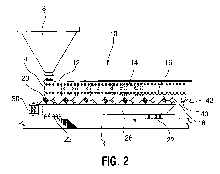
Figure 2 is a side elevational view of the vibrating screening feeder unit
illustrating natural
frequency vibrating screening feeder in which the exciter motor is suspended
from the vibratory mass
system and acts in parallel with the drive springs which are selected to give
the system natural
frequency characteristics;
Figure 3 is a view of a section of the vibrating screening feeder showing the
screening unit
connecting to drive springs mounted on brackets supported by the longitudinal
counterbalance
support base;
12
CA 02991321 2018-01-03
WO 2017/007508
PCT/US2016/000056
Figure 4 is an end view of the vibrating screening feeder showing the
screening unit
connecting to a plurality of drive springs mounted in a row across the width
of the screening unit and
longitudinal counterbalance support base which is supported by a plurality of
horizontal coil steel
isolation springs supporting the longitudinal counterbalance support base on a
base and showing a
plurality of motors mounting on the rear end of the longitudinal
counterbalance support base;
Figure 5 is a perspective view of the vibrating screening feeder unit of the
present invention
showing the screening unit side walls and pan having brackets connecting to a
plurality of drive
springs mounted in a row across the width of the screening unit and
longitudinal counterbalance
support base;
Figure 6 is an elevated perspective view of the vibrating screening feeder
unit showing the
discharge chutes extending from the rear end of the present invention;
Figure 7 shows that when the drive springs 20 are expanded, the rocker springs
24 are flexed
upward.
Figure 8 shows that when the drive springs are compressed, the rocker springs
24 are flexed
downward.
Figure 9 shows a vibratory motor with rotatable eccentric weights.;
Figure 10 shows the vibratory motor of Figure 9 including extra weights added
to the shaft;
Figure 11 is an end view of a vibrating screening feeder unit showing the
storage bin
positioned above the vibrating screening feeder and connecting the bin outlet
to the feeder inlet
interfacing chute;
Figure 12 is a side view of the vibratory screening feeder showing a chute
connecting the
13
CA 02991321 2018-01-03
WO 2017/007508
PCT/US2016/000056
bin to the feeder inlet and the screening unit supported by the longitudinal
counterbalance on drive
springs and the longitudinal counterbalance supported on the base with steel
coil isolation springs;
Figure 13 is an end view of the vibrating screening feeder showing the motors
attaching to
the rear end of the longitudinal counterbalance, a row of isolation springs
supporting the screening
unit above the longitudinal counterbalance and the drive springs on the
outside of the row extending
across the screening unit supported by the longitudinal counterbalance;
Figure 14 is an elevated side view of the vibratory screening feeder showing a
chute
connecting the bin to the feeder inlet and the screening unit supported by the
longitudinal
counterbalance on drive springs and the longitudinal counterbalance supported
on the base with steel
coil isolation springs wherein the longitudinal counterbalance is angled
downward at a 15 degree
angle with respect to the base;
Figure 15 is an elevated side view of the vibratory screening feeder of Figure
16 showing a
chute connecting the bin to the feeder inlet and the screening unit supported
by the longitudinal
counterbalance on drive springs and the longitudinal counterbalance supported
on the base with steel
coil isolation springs wherein the longitudinal counterbalance is angled
downward at a 15 degree
angle with respect to the base and showing the optional water spray bars and
discharge connection
to a crusher;
Figure 16 is an end view showing the connection of the vibrating screening
feeder to the
crusher and the discharge chute;
Figure 17 is a side elevational view of prior art showing the drive of this
invention applied
to a natural frequency vibratory feeder where the springs are in series with
the motor drive;
14
degree angle with respect to the base;
Figure 15 is an elevated side view of the vibratory screening feeder of Figure
16 showing
a chute connecting the bin to the feeder inlet arid the screening unit
supported by the longitudinal
counterbalance on drive springs and the longitudinal counterbalance supported
on the base with
steel coil isolation springs wherein the longitudinal counterbalance is angled
downward at a 15
degree angle with respect to the base and showing the optional water spray
bars and discharge
connection to a crusher;
Figure 16 is an end view showing the connection of the vibrating screening
feeder to the
crusher and the discharge chute;
Figure 17 is a side elevational view of prior art showing the drive of this
invention
applied to a natural frequency vibratory feeder where the springs are in
series with the motor
drive,
DESCRIPTION OF TIIE PREFERRED EMBODIMENTS
As shown in the figures 1-17, a vibrating screening feeder system 1 includes a
vibratory
storage bin 8 feeding a vibrating screening feeder unit 10 feeding and crusher
70 for oversized
material. The intermediate storage bin 8 is positioned above the vibrating
screening feeder 10
connecting the bin outlet 102 to the feeder inlet interfacing chute 104, The
size of the bin 8 is
determined by the throughput to maintain a maximum feed rate to the vibratory
screening feeder
10 and ensure an appropriate amount of storage to enable it to continuously
operate at its rated
TPH (ton per hour) capacity. The bin's outlet 102 is positioned close to the
feeder inlet 103
separated by the feed plate 105. Preferably the bin 8 is a vibratory bin or
hopper having the
capability to shake accumulations or bridging particles from the sidewalls to
effect a smooth flow
of feed to the vibratory screening conveyor 10.
CA 2991321 2019-08-01
As shown in Figures 2, and 11-11, a chute 104 or stove pipe can be used to
connect the
bin to the feeder inlet 104. On "start-up" the top section or cover is
temporally removed to
permit the adjustment of the "mat depth" flowing into the vibrating screening
feeder 10, When
adjusted properly, full width spreading is obtained and the cover 56 is
reinstalled over the unit.
Also shown are the horizontal coil steel isolation support springs 22 which
are nested in sets and
mounted to support members 23 extending across the width of the conveyor. The
isolation
springs 22 rest on a base, floor or other immobile support surface, A
alternate motor 58 is
shown mounted to the longitudinal counterbalance 26.
Figure 13 is an end view of the vibrating screening feeder showing the motors
attaching
to the rear end of the longitudinal counterbalance, a row of isolation springs
22 supporting the
screening unit above the longitudinal counterbalance and the drive springs 20
on the outside of
the row extending across the screening unit supported by the longitudinal
counterbalance. The
vibrating screening feeder 10 shown includes 200 drive springs 20 are arranged
in sets of two
rows each extending across the width of the conveyor attaching to the conveyor
bed frame or
integral body/frame support members 18 supported at a 45 degree angle by
brackets 19 mounted
on the top of the longitudinal counterbalance support base 26 . Each drive
spring or coil is
equivalent to 1/2 HP, Thus, 200 drive springs provide the equivalent of 100 I-
1P of driving force
to the vibrating screening feeder 10.
As shown in Figure 14, the vibratory screening feeder shows a chute connecting
the bin
to the feeder inlet and the screening unit supported by the longitudinal
counterbalance on drive
springs and the longitudinal counterbalance supported on the base with steel
coil isolation
springs wherein the longitudinal counterbalance is angled downward at a 15
degree angle with
respect to the base.
16
CA 2991321 2019-08-01
CA 02991321 2018-01-03
WO 2017/007508
PCT/US2016/000056
The drive springs 20 are preferably selected with K factors, that is, spring
rates which are
appropriately related to the frequency of the motor drive, the mass of the
motor drive component,
and the total mass of the driven vibratory system, so that under normal
synchronous speed of the
drive motor, the springs 20 will be at or near natural frequency with the
system. For ideal operation,
the vibratory system with its exciter drive is designed to operate at, as
close to, the natural frequency
of the system as illustrated by the stroke-frequency curve of Figure 7 of U.S.
Patent 4,015,705
wherein the natural frequency is at the peak of the curve.
It will be understood that the drive springs 20 are also designed so that
lateral forces
transverse to the longitudinal axis of the vibrating screening feeder 10 are
absorbed by the lateral
deflections of the springs 20 . Of course, if desired dual motors having the
same characteristics as
the motor 30, except for being each one-half the horsepower of the single
motor, may be used in
place of the single motor 30, in which case they are driven in opposite
directions and have their
motor housings rigidly joined together in a manner well known in the art so as
to cause the rotating
weights to phase together and cancel out the lateral forces while producing a
resultant linear stroke.
A motor 30 for vibrating the vibrating screening feeder 10 at a selected
frequency and stroke
for moving particulate material on the pan 11 toward the feeding forward end
15 of the feeder. The
motor drive in the present invention is capable of adjusting the rate of feed
by varying the frequency
and the stroke of the vibratory system.
An unexpected surprising and unique relationship exists between the
characteristics of the
vibratory system and the driving motor, whereby it is possible to vary not
only the frequency, but
also to simultaneously vary the stroke of a natural frequency vibrating feeder
or similar vibratory
system merely by changing the voltage on the A.C. motor 30. An A.C. squirrel
cage motor has
always been thought of as essentially a constant speed motor (except, of
course, a multi speed or
multi-winding A.C. motor)one which could not have its speed effectively varied
by voltage control.
The variable load requirements of a free mass, natural frequency, vibratory
system in relation to
speed are similar to those of a fan or a fluid pump and that it is possible to
use variations in the
17
CA 02991321 2018-01-03
WO 2017/007508
PCT/US2016/000056
voltage applied to the A.C. squirrel cage motor as an effective means for
controlling the feeding rate
of this type of vibratory system, and that, surprisingly, this can be
accomplished without motor
overload.
The ability to control feeder rate merely by voltage control lends itself to
the remote control
of systems of this type, and is far more convenient than attempting to adjust
or vary the rate of the
force-transmitting spring units interposed between the motor 30 and the
vibrating screening feeder
10.
The motor drive 30 comprises a single alternating current squirrel cage
induction motor
which is supported on the rear end of the longitudinal counterbalance 26 from
a motor mount
bracket rigidly secured thereto. The motor has a squirrel cage rotor, and is
thereby characterized as
one which does not have brushes. For convenience the type of A.C. motor will
hereinafter be
referred to simply, as an A.C. squirrel cage motor, and is to be distinguished
from a variable speed
A.C. motor having multiple windings or multipoles for speed control.
As shown best in Figures 9-10, at each end of the shaft 33 of the motor 30 an
eccentric
weight 52 is mounted, and usually these weights are fixed to the shaft in
parallel relationship,
although in some instances, it may be desirable to vary their angular relative
positions to achieve
adjustment of the effective eccentric mass operating on the vibratory system,
or adjusting weights
54 may be added to or subtracted from the eccentric weights, as required.
Shrouds cover the ends
of the motor to protect personnel from the revolving eccentric masses.
The motor 30 is supported on the longitudinal counterbalance in such a manner
that the
exciting oscillatory force supplied by the eccentrically weighted motors is
applied to the vibratory
conveyor screening unit 9 along a fixed angle of attack. This angle of attack
is ordinarily on the
order of from 20 to 40 degrees, and it will be seen that as an oscillating
force is applied to the
vibrating screen 9 along this axis, the particulate on the vibrating screen 9
is caused to move toward
the open end of the vibrating screen 9 by what might be termed a hopping
action. As the frequency
18
CA 02991321 2018-01-03
WO 2017/007508
PCT/US2016/000056
of the oscillating force is reduced and/or as the stroke is reduced, the rate
of feed is correspondingly
reduced and it is desirable to have this rate of feed variable between zero,
or substantially zero, and
the maximum rate of feed.
It is an accepted fact in the natural frequency vibrating system field (as for
example in the
type of feeder shown in Klemencik Patent No. 2,725,984) that one can normally
determine whether
the system is operating in natural frequency by checking the current draw on
the motor, because,
when the system is operating at true natural frequency, the current draw is at
a minimum.
Conversely, to the extent that a system of this type is not operating at
natural frequency, the power
requirements go up, and this is reflected in increased current draw,
regardless of whether one is
operating above or below the point of natural frequency. Contrary to
conventional teachings, when
the present invention is operating in natural frequency, the current drawn by
the motor is at its
maximum, and, as the frequency (i.e. speed) of the motor is changed by
dropping the voltage, the
current decreases. As one moves below natural frequency with the system the
current going through
the motor drops rather than rises, as might normally be expected. It is
possible to effectively vary
the feed rate of a vibratory conveying or feeding system from-substantially
zero to its maximum
feed rate, merely by adjusting the voltage of an A.C. squirrel cage motor.
This of course can
conveniently be done with an auto transformer, such as shown in Figure 17.
The vibrating screening feeder is adapted to be driven by a plurality of
accumulatively
phased pairs of free-wheeling rotatable eccentric weights. The accumulative
force output produced
by the rotating eccentric weights will be a unified amount equal to the sum of
all the multiple pairs
of eccentric weights. The respective power outputs of the motors turning these
eccentric weights will
also accumulatively add. This wanted "phasing" of multiple pairs of rotating
eccentric weights will
only occur when used in conjunction with properly stabilized, sub-resonant
tuned, stiff drive springs.
The accumulative phasing of a plurality of pairs of rotating eccentric weights
is applicable
to vibratory conveyors of the non-balanced type, which must be rigidly fixed
to their support
structure. It is also applicable to vibratory conveying machines that are
dynamically counterbalanced
19
CA 02991321 2018-01-03
WO 2017/007508
PCT/US2016/000056
and provided with isolation springs. The longitudinal counterbalance can be
one single longitudinal
assembly, or the longitudinal counterbalance can be sectionalized in a
plurality of sections as shown
in Dumbaugh U.S. Pat. No. 4,149,627. It is important to note the vibrating
screen 9 must employ
the sub-resonant tuned springs kind of vibratory drive configuration that is
properly stabilized for
this wanted multiple phasing of a plurality of pairs of rotatable eccentric
weights to occur.
The multiple pairs of rotatable eccentric weights are installed on and become
an integral part
of the conveying trough assembly of the conveying apparatus when the vibratory
conveying
apparatus is the "non-balanced" type. This means its longitudinal
counterbalance frame is rigidly
"fixed" to a robust stationary foundation. Conversely, when the vibratory
conveyor is "dynamically
counterbalanced", the pair of rotatable eccentric weights can be installed on
either the conveying
trough or on a counterbalancing member. When the conveying apparatus is
longitudinal
counterbalanced, the pair of rotatable eccentric weights are almost always
installed on the
counterbalancing member.
METHOD OF USE:
A continuous, steady flow of the supply of the incoming bulk solid such as
coal, ore, wood
waste, or the like is required as feed material for optimal control and
screening performance of the
feeding and screening system. It is recommended that the vibrating screening
feeder 10 be installed
under the outlet of a storage bin or silo or surge bin 8. The outlet 105 of
the steady feed source must
be interfaced with the vibrating screening feeder inlet chute 104 that
connects to the feed bin 8. The
chute typically includes a baffle of 30 to 60 degrees and preferably about 45
degrees to help convert
the vertical feed flow into the inlet to a horizontal or near horizontal flow
and spread across the full
width of the vibrating screen feeder feed plate 17.
The screen media 53 is usually woven wire or a perforated plate with
longitudinal side
clamps, flap plastic squares or any standard screen media. Three screening
decks, a (top deck 50,
a middle deck 55, and a bottom deck 58), and a bottom trough or pan 11 are
typically used in the
CA 02991321 2018-01-03
WO 2017/007508
PCT/US2016/000056
vibrating screening feeder 10; however, it is contemplated that additional
decks may be added. The
passed "unders" (under sized particles) collecting pan 11 is disposed beneath
the screening plates
and extends the full width and length of the screen for collecting and
conveying all of the passed
"unders" to an outlet located near to the end of the screen. The collecting
pan 11 includes an outlet
44 for discharging the "passed tinders" located near the end of the screens
and can be full width or
converging. The means for powering the vibrating screening feeder is
accomplished by motorized
an AC motor rotating unbalanced eccentric weights combined with sub-resonant
tuned steel coil
drive springs which are attached to the end of a counterbalanced support base
which is a longitudinal
structure which can be cut into sections that are bolted together if
necessary. The instant invention
concentrates and nests the steel drive coils 20 in rows at selected positions
or locations connecting
the screening unit to the longitudinal counterbalance support base 26.
The electrical control enables a full zero to maximum output adjustment by
means of adding
a standard variable frequency (VFD) combined with adjustable timers so that a
vibratory stroke of
about 2 Gees for the require screening (50 Hz at for about 25 seconds) has an
automatic capability
of a momentary "pulsing" to( 60 hertz (or higher) for a brief time of usually
3 to 5 seconds), which
generates a ver vigorous vibratory action "spurt" or "pulse" to the entire
screening body similar to
a dog shaking off water. The novel pulsing action is usually automatically
repeated to keep the
screen media clear of "pegging" or being blinded by lumps or particles )stuck
in the openings) or to
break free accumulated layers of adhesive and cohesive particles that try to
"stick" or adhere to the
surface of the screening media and the passed "unders" collecting pan 11 below
it.
A novel feature of the present invention is the control of the vibrating
screening feed by the
equipment it is feeding. For instance, if feeding a rock crusher 70, a
standard 4 to 20 ma D.C. signal
automatically controls the vibrating screening feeder's variable frequency
(VFD) control of the
vibrating screening feeder 10. The closed loop of the control circuit
comprises or consists of
monitoring the amps drawn by the rock crusher to control the feed rate of the
vibrating screening
feeder by increasing or decreasing the output of the fed from the vibrating
screen. Thus, the amps
pulled by the equipment being fed will control the rate of feed. The variation
form zero to
21
CA 02991321 2018-01-03
WO 2017/007508
PCT/US2016/000056
maximum TPH output and the repeated "pulsing" of making the motor with
eccentric weights to go
faster and then return to a slower, steady speed is accomplished with the 3
phase A.C. squirrel cage
motor.
More particularly, there is provided a vibrating screen unit 9 comprising,
consisting of, or
consisting essentially of a generally rectangular frame 88 supported by a
fixed base defining a
longitudinal counterbalance 26 by a plurality of upward extending isolation
support coil springs 22
fixedly attaching to a top surface of the longitudinal counterbalance 26 and
fixedly attached to a
bottom surface of the generally rectangular frame 8. The intermediate frame 8
has triangular
shaped support members 18 defining alternating large and small triangular
abutments extending
upward therefrom. The large triangular abutments have a first side forming
about a forty-five degree
angle with atop surface of the longitudinal counterbalance 26. The first side
of the large triangular
abutment 18 have a drive coil spring 20 extending upward therefrom at about a
forty-five degree
angle with a top surface of the longitudinal counterbalance 26. The small
triangular abutment has
two spaced apart leaf spring rockers 24 extending upward at about a forty-five
degree angle with the
top surface of the longitudinal counterbalance 26. The first side of the large
abutment faces toward
the second side of the small abutment. A generally rectangular vibrating
screen housing 79 has at
least two rows of downward extending trapezoidal abutments on a bottom surface
thereof. The
trapezoidal abutments fixedly connect on a third side to free ends of the
upward extending drive coils
and on a fourth side to free ends of the upward extending leaf springs. The
vibrating screen
20 housing 79 has at least one screen and preferably a plurality of screens
extending the width and
length of the frame 8, an input hopper 88 and at least two output apertures
formed therein. The
longitudinal counterbalance support base 26 has a plurality of motors 30
mounted at a rear end
thereof. The motors have output shafts extending from top and bottom ends with
eccentric weights
mounted on the shafts in mechanical time with one another. A programmable
motor control unit is
capable of driving the motors with the weights synchronized with one another
and capable of driving
the motors at a selected speed and of periodically changing the speed for a
selected time interval by
a selected amount.
22
CA 02991321 2018-01-03
WO 2017/007508
PCT/US2016/000056
The present application provides a vibrating screen for separating different
sizes of
aggregate in a continuous flow process wherein aggregate flows into a hopper,
down onto one end
of a vibrating screen, and is transported over the screen by vibration of the
screen. Fine and medium
sized portions of the aggregate fall through the first screen to a second
screen. Only fine portions
fall through the second screen. Thus the aggregate is separated into three
grades of material. The
vibrating screen is rotatably connected to a moveable intermediate base member
by a plurality of leaf
springs fixedly connected at about a forty-five degree angle between the
longitudinal counterbalance
26 and the vibrating screen frame unit 9 and a plurality of coil springs
called 'drive springs' 20
which are connected at 45 degrees with the leaf springs between the
longitudinal counterbalance and
the vibrating screen. The longitudinal counterbalance in turn is supported
above a fixed base
member by vertical coil springs 22. The longitudinal counterbalance includes a
number of electric
motors 30 which have eccentric weights connected directly to the shafts. When
the motors are
running the spinning eccentric weights cause the vibrating screening frame 10
to vibrate at a
frequency consistent with the speed of the motors. The speed of the motors can
be varied to give a
different vibrating frequency.
The mostly horizontal left and right motion of the intermediate base member
therefore causes
a left to right and an up and down motion of the vibrating screen housing 79.
It can also be seen
that, primarily, the 'drive springs' 20, and to a smaller degree, both the
leaf springs 24 and the drive
springs 20, store and release energy every cycle of movement. This system of
springs establishes
a harmonic system which tries to maintain a frequency of movement of the
system. This storing and
releasing of energy allows for a more efficient system with fewer and smaller
drive motors for a
given throughput of aggregate.
The motors 30 are variable speed and run at one selected speed most of the
time.
Periodically, however, the speed is changed by a selected amount for a
selected period of time and
then returned to normal. This change in speed dislodges jams or clogs that
occasionally occur in the
process, due to density and particle variance, moisture, and so forth. The
vibrating screen of the
present invention gives superior performance where moist aggregate is an
issue.
23
CA 02991321 2018-01-03
WO 2017/007508
PCT/US2016/000056
A programmable motor controller easily accomplishes this periodic cycle of
motor speed
change. A user can easily change the cleaning cycle time and amount of speed
change, as desired.
The preferred embodiment includes an input hopper with a vibratory motor 31 to
vibrate the
provide consistent feed rate of aggregate onto the vibrating screens. Another
preferred embodiment
has a hopper without a separate vibratory drive motor and wherein the gap
between the bottom of
the hopper is adjusted manually to give an ideal flow of aggregate over the
input end of the vibrating
screen. This hopper is preferably fitted with a device which strikes the side
of the hopper periodically
or whenever a bridging or clogging of aggregate is detected.
It is anticipated that a feed box may be used between the hopper and the
vibratory screen
comprising a short length conveying trough utilized at the inlet end of the
conveyor where the
incoming bulk solid needs to be stratified to avoid abrasive wear from
impacting and the unnecessary
blinding of the screen medium on its upstream extremity. The feed to the
screening unit needs to
be uniform and with a reasonable spread across its width.
Referring now to the drawings, the vibration drive isolation system or
assembly is arranged
to minimize vibration to exterior plant equipment. Vibration drive isolation
system includes a
longitudinal counterbalance member 26, a plurality of drive springs 20
supported by longitudinal
counterbalance member 26 and a plurality of isolation springs 22 supporting
the longitudinal
counterbalance member 26. A structural steel base 4 supports the isolation
springs 22. The vibration
unit has a variable speed motor control capable for adjusting the vibration
intensity.
Both the time between oscillations and the intensity of the oscillation can be
controlled with
an easy control panel adjustment of controller. They require no mechanical
adjustment of
eccentrics.
The electric motors 30 of the vibratory drive assembly are attached to the
dynamic counter-
balance 26 1 and positioned at the rear or under the combination of the steel
coil drive springs 20
24
CA 02991321 2018-01-03
WO 2017/007508
PCT/US2016/000056
and multiple flat bar type of stabilizers. The assembly is supported from the
longitudinal counter-
balance 26 by the appropriately spaced isolating springs 22 mounted in
compression and
appropriately spaced along its length. The vibratory motors with shaft mounted
eccentric weights
30 are either installed on each side of the counter-balance 180 as shown in
FIG. 7, or combined
together, and placed at the rear of the counter-balance.
The steel coil type drive springs 20 are distributed across the width and
along the length of
the underside of the screen unit 9. The drive springs 20 are combined with
flat bar type stabilizers
24 to assure a uniform stroking action. The flat bar type stabilizers 24 are
used to guide the
movement of the stiff drive springs 20.
The drive springs 20 are sub-resonant tuned to cause them to inherently work
harder under
load, where sub means under and Resonant means natural frequency. Therefore,
"Sub-resonant"
means the maximum running speed of the vibratory motors 30 is always under the
natural frequency
of the combined drive springs. For example, if the top motor speed is 570 RPM,
which in this
instance is the same as CPM, then the natural frequency of all the drive
springs 182 would be, for
example, 620 CPM. While 570 CPM is preferred, other frequencies such as 720
CPM, 900 CPM or
1200 CPM, might be useful for various applications.
The axial centerline of the steel coil drive springs 20 is provided in line
with the wanted
stroke angle, but the axial centerline of the stabilizer 24 is perpendicular
to the stroke angle. By
utilizing paralleled counter-balance or structural beams 26 as a longitudinal
configuration, the
enclosed vibrating screening feeder 10 is dynamically counter-balanced. The
structural Natural
Frequency of the counter-balance assembly will be at least 1.4 times the
maximum speed of the
motors, but preferably will exceed it. In this instance, the RPM of the motor
30 is the same as the
vibrating CPM of the enclosed vibrating screening feeder 10.
Relatively soft steel coil type isolation springs 22 are used to support the
longitudinal
counter-balance 26 which in turn supports the enclosed vibrating screening
unit 9 above it.
CA 02991321 2018-01-03
WO 2017/007508
PCT/US2016/000056
Preferable needed input power is proved by three phase, A-C squirrel cage
vibratory motors 30.
Electrical adjustment of conveying speed is provided by the controller
implements either as a
variable voltage or an adjustable frequency type of electrical control. The
conveying speed of the ash
over the vibrating screening feeder 10 can be electrically adjusted.
In operation, the vibratory motor(s) 30 are energized and the shaft mounted
eccentric weights
are accelerated to full speed. The force output of the rotating eccentric
weights excites or induces
all the stiff steel coil drive springs 20 and flat bar stabilizers 24 to
vibrate back and forth in a straight
line. The speed (RPM) of the vibratory motors 30 is the same as the vibrating
frequency (CPM) of
the drive springs 20. This happens even though the natural frequency of the
drive springs 20 is above
the motor speed. Consequently, the enclosed vibrating screening feeder 10
vibrates at a prescribed
amount of linear stroke at the wanted angle, which is usually 45 degrees. As
an equal reaction to the
vibratory movement of feeder 10 , the counter-balance member 26 inherently
moves in an opposite
direction. Thus, the opposing dynamic forces cancel one another. The counter-
balance 26 freely
moves or floats on top the soft isolation springs 22 supporting it.
A resulting directional, straight line stroke on the enclosed unit induces the
particles to
unidirectional move forward simultaneously over the screens and pan. This
particle movement is the
result of a series of hops or pitches and catches by the applied vibration.
Normally, the particles first
settles on screen. Then, it is gradually moved forward by repetitive on and
off cycles of applied
vibration. For example, the particles are moved 3 feet every 6 minutes.
Alternatively, the particle
movement over the screen surfaces could be electrically adjusted via
adjustment of motor operation
by controller to provide, for example, a conveying speed of 0.5 FPM. The
particles conveyed on the
screens discharges into vertical chutes. The particle sifting that fall
through any openings in the
screens drop onto the bottom conveying pan 11. When the vibratory conveying
action is applied,
these particles move forward. Eventually, these particles fall down through
outlets located near the
discharge end of the screening unit 9.
The vibrating screening feeder 10 includes a plurality of vibratory motors 30
placed relatively
26
CA 02991321 2018-01-03
WO 2017/007508
PCT/US2016/000056
close together on the rear or back section 14 of the longitudinal
counterbalance 26. In one
embodiment, a total of six vibratory motors are disposed transversely across
from one another with
respect to the longitudinal width of the vibrating screening feeder 10. Each
vibratory motor includes ,
a rotatable eccentric weight. Since the rotating eccentric weights are located
on the top and bottom
of each motor, a total of twelve individual eccentric weights would be
involved, but all of the
eccentric weights on a single motor are considered herein to be a single
eccentric weight. The
eccentric weight attached to one of the vibratory motors in a pair of
vibratory motors is substantially
equal in size to the eccentric weight attached to the other vibratory motor in
the pair of vibratory
motors. Each motor is rated 45-60 HP, which would make a total of 270 - 300 HP
provided by the
six vibratory motors although other sizes of motors can be used. While
electric motors are
preferred, air motors or hydraulic motors can also be used.
Each vibratory motor preferably has the substantially same size eccentric
weight attached
thereto, such that each vibratory motor and eccentric weight produce
substantially the same force
output during operation.
All six motors synchronize and provide an accumulatively phased force output
equal to the
sum of the individual force outputs of all of the eccentric weights. The
proper phasing of the
eccentric weights happens if each pair of motors is started separately, or in
any combination, or all
started at the same time. These motors would still try to "phase" even if the
rotation was different
when these six motors are working in conjunction with sub-resonant tuned steel
coil drive springs
that have flat bar type stabilizers to guide their stroke line.
The goal is to make the load carrying vibrating screening feeder 10 to vibrate
at a prescribed
stroke of, for example, one-half inch at a frequency of 570 cycles per minute
(CPM), which is the
same as the rotational speed of the motors at 570 revolutions per minute
(RPM). In other words, the
operating frequency of the conveying apparatus 10 in CPM is the same as the
RPM of the motors.
After being energized at the same time all six the motors accelerate the
rotatable eccentric
27
CA 02991321 2018-01-03
WO 2017/007508
PCT/US2016/000056
weights installed on the top and bottom shaft extension of the motors. While
the weights are
accelerating, a slight "shimmy" or shudder-like movement may be present. After
all six motors have
reached full speed, the stroke on the conveying trough assembly begins to grow
steadily from, for
example, from one-eighth inch to the desired maximum of one-half inch in about
twenty seconds.
Thus, the three pairs of motor combinations require about ten to twenty
seconds after being
energized to accelerate the eccentric weights and to properly "phase" or to
accumulatively
synchronize the outputs of the eccentric weights.
All of the rotating eccentric weights may have exactly the same force output.
If any of these
motors is de-energized, then the resulting stroke on the vibrating screening
feeder will decrease
from its maximum amount.
The "phased" or synchronized eccentric weights on the vibratory motors excite
or prompt the
steel coil drive springs 20 to move back and forth, or compress and extend, in
a straight line of
stroke. That "line" is guided by the flat bar type stabilizers 24 installed at
90 degrees or perpendicular
to the axial centerline of the steel coil drive springs 20. The vibratory
screening unit 9 positioned on
top of the drive spring brackets vibrates back and forth in reaction to the
movement of the
longitudinal counterbalance 26 below. This is in keeping with Newton's Law of
an "equal and
opposite reaction". Stabilization of the drive springs 20 must be relatively
rigid in a direction
transverse to the line of stroke and relatively weak in the direction of
stroke. For example, the flat
bar stabilizer 24 may be five inches wide across its transverse width and only
one-eighth inch thick
in the direction of the stroke. If the drive springs 20 are not rigidly
stabilized in a direction transverse
to the line of stroke, then the rotating eccentric weights may not
synchronize. The stabilizers 24 may
be formed in other configurations than as flat bars so long as the stabilizer
is relatively rigid in a
direction transverse to the line of stroke and relatively weak in the
direction of stroke. The vibratory
motors are tilted or inclined from horizontal to agree with the stroke line
and the installed inclined
angle of the drive springs 20.
The entire apparatus vibrates very smoothly and quietly when all six motors
are up to their
28
CA 02991321 2018-01-03
WO 2017/007508
PCT/US2016/000056
full speed. The amount of vibratory stroke remains constant or steady. A given
amount of bulk solid,
such as foundry sand, in the vibrating screening feeder installed above the
longitudinal
counterbalance 26 can be conveyed forward at a steady speed of, for example,
approximately forty
feet per minute (FPM).
In another embodiment, the stiff steel coil drive springs 20 have a combined
natural
frequency that is always above the maximum speed of the motors being utilized.
"Sub" means
"under" and "resonant" means "natural frequency". Therefore, "sub-resonant"
means to maintain the
top running speed of the motor (for example, 600 RPM or CPM) to always be
under the "natural
frequency" of all the steel coil drive springs 20 (for example, 650 CPM) when
the vibratory conveyor
10 is in the "no load" state or empty condition. When a load is applied to the
vibrating screening
feeder the "natural frequency" of all the installed drive springs 20 will
inherently reduce in response
to the added weight of the load (for example, to 625 CPM). Because the natural
frequency of the
drive springs 20 has decreased (from 650 to 625 CPM), and moved closer to the
motor speed (600
RPM or CPM), the entire drive configuration works harder. The more the natural
frequency of the
drive springs decreases because of additional load being added to the
vibrating screening feeder, the
more close the natural frequency of all the drive springs 20 comes to the
running speed of the motors.
Thus, the drive configuration works even harder. This is the advantage of "sub-
resonant" tuning.
Consequently, the stiff steel coil drive springs 20 in combination with the
six motors
inherently drive harder when load is applied to the vibrating screening feeder
10. Therefore, the use
of "sub-resonant" tuning takes advantage of the principal of "natural
frequency". However, it should
be noted this kind of drive configuration does not normally operate in
"natural frequency".
The objective is to make the respective force outputs of the eccentric weights
to "pull" the
screens of the vibrating screening feeder 10 in tension from the discharge end
as compared to
"pushing" the inertial mass in compression from the inlet end. The same
relationship is wanted from
the total number of drive springs 20 installed that help to make the apparatus
vibrate. This is the
reason the collective forces from both the rotating eccentric weights and the
drive springs should
29
CA 02991321 2018-01-03
WO 2017/007508
PCT/US2016/000056
place the overall length of the vibratory apparatus in tension as compared to
being in compression.
More simply stated, the vibratory apparatus is dynamically being "pulled"
instead of being "pushed".
When an electrical means for adjusting the operating stroke and frequency of
the vibratory
machine is wanted, it is preferred to be large enough to control the total
combination of paired
motors installed on the vibratory apparatus. To ensure each of those
individual controllers are
responding to the same electrical pilot signal (usually 4 to 20 ma D.C.) to
ensure each of the motors
is rotating at the same speed throughout the range of adjustment. This maybe
accomplished by use
of a common electrical potentiometer on either the variable voltage or the
frequency inverter type
of electrical controls. The simultaneous adjustment of the operating stroke
and frequency by means
of a variable voltage electrical control as outlined in U.S. Pat. Nos.
3,251,457 and 4,015,705 can be
successfully utilized. As a substitute for the variable voltage control, a
frequency inverter can also
be utilized.
Since these motors are combined with sub-resonant tuned drive springs 20 that
are properly
stabilized by stabilizers 24, the plurality of motors requires less work
output to align with the
movement of the stiff drive springs 20 than it would be to try to be "out of
step" or not phased or
accumulatively synchronized with all the sub-resonant tuned drive springs 20.
The foregoing detailed description is given primarily for clearness of
understanding and no
unnecessary limitations are to be understood therefrom, for modification will
become obvious to
those skilled in the art upon reading this disclosure and may be made without
departing from the
spirit of the invention and scope of the appended claims. Accordingly, this
invention is not intended
to be limited by the specific exemplification presented herein above. Rather,
what is intended to be
covered is within the spirit and scope of the appended claims.