Note: Descriptions are shown in the official language in which they were submitted.
CA 02992080 2018-01-10
DESCRIPTION
TRAFFIC LIGHT RECOGNITION DEVICE AND TRAFFIC LIGHT RECOGNITION
METHOD
TECHNICAL FIELD
[0001]
The present invention relates to a traffic light recognition device and a
traffic
light recognition method for recognizing a traffic light, the traffic light
recognition
device being mounted on a vehicle.
BACKGROUND ART
[0002]
For example, a vehicle provided with an automatic operation function controls
the operations to stop, travel, and so on by recognizing a traffic light
provided along a
traveling path of the vehicle and detecting a lighting state, such as lighting
color, of the
traffic light.
[0003]
As a conventional traffic light recognition device, there is known, for
example,
the one disclosed in Patent Literature 1 (Japanese Patent Laid-Open
Publication No.
11-306489). In this cited Literature 1, a camera is mounted on a vehicle and
images a
traffic light ahead. In this case, the angle in the horizontal direction and
the angle in
the vertical direction of the camera are controlled so that the traffic light
is located at the
center of an image captured by the camera. Furthermore, the magnification is
controlled so that the image of the traffic light has a desired size.
CITATION LIST
PATENT LITERATURE
[0004]
Patent Literature 1: Japanese Patent Laid-Open Publication No. 11-306489
1
SUMMARY OF INVENTION
[0005]
However, in the conventional example disclosed in Patent Literature 1, a
blur occurs in the image captured by a camera while changing the imaging
direction of the camera, thus making the image recognition difficult. As the
result, while changing the imaging direction of the camera the accuracy to
detect
the lighting state of a traffic light might decrease.
[0006]
The present invention has been made in order to solve the above-described
conventional problems, and an object thereof is to provide a traffic light
recognition device capable of eliminating the need to change the imaging
direction of an imaging unit or reducing the number of times of changing the
imaging direction, when a vehicle approaches a traffic light.
[0007]
According to an aspect of the present invention there is provided a traffic
light recognition device, comprising:
an imaging unit mounted on a vehicle and configured to capture an image
around the vehicle;
a map information acquisition unit configured to acquire map information
around the vehicle;
a vehicle current position detector configured to detect a current position
on a map of the vehicle;
a traffic light position estimator configured to estimate a position on an
image of a traffic light on a basis of the current position and the map
information;
an imaging direction setting unit configured to set an imaging direction of
the imaging unit on a basis of the position on the image of the traffic light
and of
a moving direction in the future on the image of the traffic light;
an imaging direction change unit configured to change the imaging
direction of the imaging unit to an imaging direction set by the imaging
direction
setting unit; and
2
CA 2992080 2018-03-26
a traffic light recognition unit configured to recognize the traffic light
from an image captured in the imaging direction by the imaging unit, wherein
the imaging direction change unit sets a change point or region at which
the imaging direction change unit changes the imaging direction of the imaging
unit, on a basis of the position on the image of the traffic light and of the
moving
direction in the future on the image of the traffic light, and
the imaging direction change unit changes the imaging direction in
advance when the vehicle reaches the change point or region.
According to another aspect of the present invention there is provided a
traffic light recognition device, comprising:
an imaging unit mounted on a vehicle and configured to capture an image
around the vehicle;
a map information acquisition unit configured to acquire map information
around the vehicle;
a vehicle current position detector configured to detect a current position
on a map of the vehicle;
a traffic light position estimator configured to estimate a position on an
image of a traffic light on a basis of the current position and the map
information;
an imaging direction setting unit configured to set an imaging direction of
the imaging unit on a basis of the position on the image of the traffic light
and of
a moving direction in the future on the image of the traffic light;
an imaging direction change unit configured to change the imaging
direction of the imaging unit to an imaging direction set by the imaging
direction
setting unit; and
a traffic light recognition unit configured to recognize the traffic light
from an image captured in the imaging direction by the imaging unit, wherein
the imaging direction setting unit sets, when a plurality of traffic lights
synchronously operated can be imaged by the imaging unit, an imaging direction
of the imaging unit on a basis of a moving direction of a traffic light, among
the
plurality of traffic lights synchronously operated, whose movement amount on
the image becomes the minimum.
3
CA 2992080 2019-05-29
[0008]
According to a further aspect of the present invention there is provided a
traffic light recognition method, comprising the steps of:
capturing, by an imaging unit, an image around a vehicle;
acquiring map information around the vehicle;
detecting a current position on a map of the vehicle;
estimating a position on an image of a traffic light on a basis of the current
position and the map information;
setting an imaging direction of the imaging unit on a basis of the position
on the image of the traffic light and of a moving direction in the future on
the
image of the traffic light;
changing the imaging direction of the imaging unit to a set imaging
direction;
recognizing the traffic light from an image captured in the imaging
direction by the imaging unit;
setting a change point or region at which the imaging direction of the
imaging unit is changed, on a basis of the position on the image of the
traffic light
and of the moving direction in the future on the image of the traffic light;
and
changing the imaging direction of the imaging unit in advance when the
vehicle reaches the change point or region.
BRIEF DESCRIPTION OF DRAWINGS
[0009]
[Fig. 1] Fig. 1 is a block diagram illustrating a configuration of a traffic
light recognition device according to an embodiment of the present invention
and
of the peripheral devices thereof.
[Fig. 2] Fig. 2 is a block diagram illustrating the detailed configuration of
the
traffic light recognition device according to an embodiment of the present
invention.
[Fig. 3] Fig. 3 is a block diagram illustrating the detailed configuration of
an imaging attitude setting unit according to a first embodiment.
3a
CA 2992080 2019-08-29
[Fig. 4] Fig. 4 is a flow chart illustrating a processing procedure of a
traffic
light recognition device according to the first embodiment.
[Fig. 5] Fig. 5 is an explanatory view illustrating the current position
coordinate of a traffic light present in an image.
[Fig. 6] Fig. 6 is an explanatory view illustrating the past position
coordinate and current position coordinate of the traffic light present in the
image.
[Fig. 7] Fig. 7 is an explanatory view illustrating how the position
coordinate of the traffic light has moved in the lower left of an image by
changing
the imaging direction of a camera.
[Fig. 8] Fig. 8 is an explanatory view illustrating the timing for changing
the
imaging direction of the traffic light recognition device according to the
first
embodiment, Fig. 8(a) illustrates the traveling route of a vehicle, Fig. 8(b)
illustrates an
3b
CA 2992080 2018-03-26
CA 02992080 2018-01-10
image before changing the imaging direction, and Fig. 8(c) illustrates an
image after
changing the imaging direction.
[Fig. 9] Fig. 9 is a block diagram illustrating the detailed configuration of
an
imaging attitude setting unit according to a second embodiment.
[Fig. 10] Fig. 10 is a flow chart illustrating a processing procedure of a
traffic
light recognition device according to the second embodiment
[Fig. 11] Fig. 11 is an explanatory view illustrating the timing for changing
the
imaging direction of the traffic light recognition device according to the
second
embodiment, Fig. 11(a) illustrates the traveling route of a vehicle, Fig.
11(b) illustrates
an image before changing the imaging direction, and Fig. 11(c) illustrates an
image after
changing the imaging direction.
[Fig. 12] Fig. 12 is an explanatory view illustrating the movement locus of a
traffic light on an image when a vehicle travels a curve road.
[Fig. 13] Fig. 13 is an explanatory view illustrating the timing for changing
the imaging direction of a traffic light recognition device which does not
employ the
second embodiment, Fig. 13(a) illustrates the traveling route of a vehicle,
Fig. 13(b)
illustrates an image before changing the imaging direction, and Figs. 13(c)
and 13(d)
illustrate an image after changing the imaging direction.
[Fig. 14] Fig. 14 is an explanatory view illustrating the timing for changing
the imaging direction of a traffic light recognition device according to a
third
embodiment, Fig. 14(a) illustrates the traveling route of a vehicle, Fig.
14(b) illustrates
an image before changing the imaging direction, and Fig. 14(c) illustrates an
image after
changing the imaging direction.
[Fig. 15] Fig. 15 is an explanatory view illustrating the timing for changing
the imaging direction of a traffic light recognition device which does not
employ the
third embodiment, Fig. 15(a) illustrates the traveling route of a vehicle,
Fig. 15(b)
illustrates an image before changing the imaging direction, and Fig. 15(c)
illustrates an
image after changing the imaging direction.
[Fig. 16] Fig. 16 is an explanatory view illustrating the timing for changing
the imaging direction of a traffic light recognition device according to a
modified
4
CA 02992080 2018-01-10
example of the third embodiment, Fig. 16(a) illustrates the traveling route of
a vehicle,
Fig. 16(b) illustrates an image before changing the imaging direction, and
Fig. 16(c)
illustrates an image after changing the imaging direction.
[Fig. 17] Fig. 17 is an explanatory view illustrating the timing for changing
the imaging direction of a traffic light recognition device according to a
fourth
embodiment, Fig. 17(a) illustrates the traveling route of a vehicle, Fig.
17(b) illustrates
an image before changing the imaging direction, and Figs. 17(c), 17(d) and
17(e)
illustrate an image after changing the imaging direction.
[Fig. 181 Fig. 18 is an explanatory view illustrating the timing for changing
the imaging direction of a traffic light recognition device according to a
fifth
embodiment, Fig. 18(a) illustrates the traveling route of a vehicle, Fig.
18(b) illustrates
an image before changing the imaging direction, and Fig. 18(c) illustrates an
image after
changing the imaging direction.
DESCRIPTION OF EMBODIMENTS
[0010]
Hereinafter, embodiments of the present invention will be explained with
reference to the drawings.
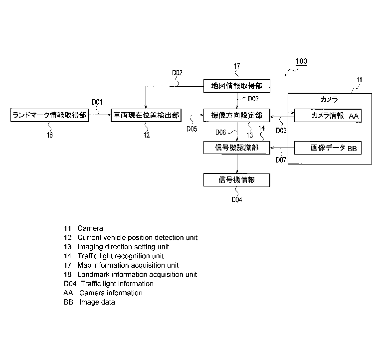
[Explanation of First Embodiment]
Fig. I is a block diagram illustrating a configuration of a traffic light
recognition device according to a first embodiment of the present invention
and of the
peripheral devices thereof. Further, Fig. 2 is a block diagram illustrating
the detail of a
traffic light recognition device 100 illustrated in Fig. I. As illustrated in
Fig. 1, the
traffic light recognition device 100 is mounted on a vehicle 51, and receives
inputs of
map information D02, camera infoimation D03, vehicle current position
information
D05, and image data D07 from various devices mounted on this vehicle 51. Then,
the
traffic light recognition device 100 outputs traffic light information D04,
which is the
information recognized by this traffic light recognition device 100, to an
apparatus at
the subsequent stage.
[0011]
5
CA 02992080 2018-01-10
The camera information D03 is the information about the installation position
of a camera 11 (see Fig. 2) relative to the vehicle 51. Upon acquisition of
three
dimensional (3D) information indicative of the directions on a map of the
vehicle 51, an
imaging area around the vehicle can be estimated by the camera 11 on the basis
of the
camera information D03.
[0012]
The map information D02 is the information provided from a map data base
including the map data (map information around a vehicle) of a traveling path
on which
a vehicle travels, and includes the position information about a target, such
as a ground
landmark present along the traveling path, the position information about a
traffic light,
and the like.
[0013]
As illustrated in Fig. 2, the traffic light recognition device 100 includes
the
camera 11 (imaging unit), a vehicle current position detector 12, a map
information
acquisition unit 17, an imaging direction setting unit 13, a traffic light
recognition unit
14, and a landmark information acquisition unit 18.
[0014]
The camera 11 is a camera provided with a solid state image sensor, such as a
CCD or a CMOS, for example, and is installed on the vehicle 51 and captures an
image
around a traveling path to acquire a digital image of a peripheral area. The
camera 11
outputs the captured image as the image data D07 to the traffic light
recognition unit 14.
Moreover, the camera 11 has stored therein the information about the
installation
position of the camera 11 relative to the vehicle 51, and outputs this
information as the
camera information D03 to the imaging direction setting unit 13. For the
information
about the installation position of the camera 11, for example a mark or the
like for
calibration is installed at a position known to the vehicle 51, so that the
installation
position can be calculated from a position on an image captured by the camera
II.
Furthermore, the camera 11 is installed via a mechanism which is rotatable in
the pan
and tilt directions relative to the vehicle 51, includes a driving mechanism
for driving
the rotation angles in the pan and tilt directions, and can control the
attitude of the
6
CA 02992080 2018-01-10
camera 11 so that the camera 11 faces in a desired imaging direction by
driving the
rotation angles in the pan and tilt directions.
[0015]
The map information acquisition unit 17 acquires the position information
about a target, such as a ground landmark, present around a traveling path,
the position
information about a traffic light, and the like from a map data base including
the map
information (map information around a vehicle) about the traveling path on
which a
vehicle travels. The map information acquisition unit 17 outputs this map
information
as the map information D02 to the vehicle current position detector 12 and
imaging
direction setting unit 13.
[0016]
The landmark information acquisition unit 18 is, for example, a sensing
camera, laser radar, or the like mounted on a vehicle, and recognizes ground
landmarks
(road marks (lane marks, stop lines, texts), a curbstone, a traffic light, a
sign, etc.) to
acquire the information about the relative position relative to the vehicle
51. The
landmark information acquisition unit 18 outputs the acquired information as
landmark
information DO1 to the vehicle current position detector 12.
[0017]
The vehicle current position detector 12 acquires the landmark information
DO1 and map information D02, detects a current position on a map of the
vehicle 51 on
the basis of these pieces of information, and outputs this as the vehicle
current position
information 1)05. As previously described, the landmark information DOI
includes the
information indicative of the relative positional relationship of a ground
landmark
relative to the vehicle 51. Accordingly, a current position on the map of the
vehicle 51
can be detected by collating the position information about this landmark
information
DOI with the position information about a ground landmark included in the map
information D02. Here, "position" includes a coordinate and an attitude.
Specifically,
the position of a ground landmark includes the coordinate and attitude
thereof, and the
position of the vehicle 51 includes the coordinate and attitude thereof. The
vehicle
current position detector 12 outputs, as the vehicle current position
information D05, a
7
CA 02992080 2018-01-10
coordinate (x, y, z) in a coordinate system serving as a reference and an
attitude (yaw,
pitch, roll) which is in the rotation direction in each coordinate axis.
[0018]
The imaging direction setting unit 13 controls, on the basis of the vehicle
current position information DOS and the map information 1)02, the attitude in
the
imaging direction of the camera 11 so that a traffic light present along a
traveling path
of the vehicle 51 is located within the imaging area of the camera 11.
Specifically, the
attitude of the camera II can be controlled by driving the rotation angles in
the pan and
tilt directions of the camera 11 so as to be in a target imaging direction.
Then, from an
image captured in this imaging direction, a detection area, in which a traffic
light is
assumed to be present, is set and output as detection area information D06.
That is,
once the attitude of the camera 11 is determined and the area to be imaged is
set, a
position at which a traffic light is assumed to be present on an image
captured by the
camera 11 can be identified. Therefore, an area including this position can be
set as
the detection area. This detection area information 1)06 is output to the
traffic light
recognition unit 14. In this case, a detection area is set so as to have such
a size that
each traffic light will not frame out from within the detection area even when
an error
occurs in the vehicle behavior and/or vehicle current position information.
The
imaging direction setting unit 13 is provided with a function to determine the
imaging
direction of the camera 11 on the basis of the position of the vehicle 51, the
position of a
traffic light, and a change amount of the position of a traffic light. The
detail of the
imaging direction setting unit 13 will be described later with reference to
Fig. 3.
[0019]
The traffic light recognition unit 14 recognizes a traffic light on the basis
of the
above-described detection area information 1)06 from the image data D07
captured by
the camera 11. Specifically, on the basis of the image data D07 output from
the
camera 11 and the detection area information D06 set by the imaging direction
setting
unit 13, image processing for recognizing a traffic light is performed on a
detection area.
As the method for image processing, a signaling lamp of a traffic light can be
detected
using, for example, a method for detecting a signaling lamp of a traffic light
by using a
8
CA 02992080 2018-01-10
blinking light in synchronization with the alternating current (AC) cycle of a
commercial power supply or a method for determining similarity between the
characteristics, such as the hues and round shapes of red, green, and yellow
lamps, or
the like. Other than these methods, a known image processing for detecting a
traffic
light can be applied. Recognition processing of a traffic light is performed
not on the
whole image data 1)07 captured by the camera 11 but on a detection area set as
a part
thereof, so that the load in the information processing for detecting a
traffic light can be
reduced and a traffic light can be detected quickly. Then, the traffic light
recognition
unit 14 outputs the recognition result of a traffic light as the traffic light
information
D04. Note that the recognition processing of a traffic light is not limited to
the
above-described method, and the other methods can also be employed.
[0020]
Fig. 3 is a block diagram illustrating the detailed configuration of the
imaging
direction setting unit 13. As illustrated in Fig. 3, the imaging direction
setting unit 13
includes a traffic light position estimator 21, a position change amount
calculator 22, an
imaging attitude setting unit 23, a camera attitude controller 24, and a
detection area
calculator 25.
[0021]
The traffic light position estimator 21 receives inputs of the map information
1)02 and vehicle current position information 1)05 and outputs detection
position
information 1)08. Since the map information D02 includes the coordinate of
each
traffic light, the traffic light position estimator 21 can obtain the relative
coordinate of a
traffic light relative to the vehicle 51 on the basis of the coordinate of
each traffic light,
the coordinate of the vehicle 51, and the attitude of the camera 11.
Accordingly, once
the attitude when the camera 11 images a periphery is determined, a position
on an
image can be identified at which position a traffic light on a captured image
would be
imaged. For example, as illustrated in Fig. 5, within an image R1 an estimated
position (x2, y2) of a traffic light can be set. That is, the traffic light
position estimator
21 is provided with a function to estimate the position of a traffic light on
the basis of
the map information around the vehicle 51.
9
CA 02992080 2018-01-10
[0022]
The position change amount calculator 22 calculates a change amount of the
position of a traffic light within the image Rl. That is, as illustrated in
Fig. 6, within
the image R1, a past detection position coordinate (x 1, yl) and a current
detection
position coordinate (x3, y3) are acquired to calculate a position change
amount on the
image of a traffic light. Then, the calculated position change amount on the
image of
the traffic light is output as detection position change information D09.
Specifically, a
difference in the x-coordinate (x3-x1)=dx and a difference in the y-coordinate
(y3-y1)=dy are calculated to obtain change amount (dx, dy). In this case,
provided that
the attitude of the camera 11 is set to the same between at past detection and
at current
detection. Moreover, as the past detection position coordinate, the coordinate
one
detection cycle earlier can be used. Alternatively, the coordinate two or more
cycles
earlier may also be used if noise would not be superimposed. That is, the
position
change amount calculator 22 is provided with a function to calculate a change
amount
with the lapse of time of the position of a traffic light estimated by the
traffic light
position estimator 21.
[0023]
The imaging attitude setting unit 23 refers to the above-described change
amount (dx, dy) and estimates the moving direction of a traffic light within
the image
RI from this change amount. Then, on the basis of the estimated moving
direction, the
imaging direction of the camera 11 is determined so that a traffic light will
not frame
out from within the image Rl. Specifically, the change direction of a traffic
light
within the image RI is obtained from the above-described change amount (dx,
dy), and
the imaging direction of the camera 11 is determined so that a traffic light
is located in
place within the image RI on the opposite direction side of this change
direction. That
is, the imaging attitude setting unit 23 is provided with a function, as the
imaging
direction setting unit, to determine the imaging direction of the camera 11 on
the basis
of the position of the vehicle 51, the position of a traffic light estimated
by the traffic
light position estimator 21, and a change amount of the position of a traffic
light.
[0024]
CA 02992080 2018-01-10
As illustrated in Fig. 5 described above, when a traffic light is present at
the
point of reference sign q1 on the right side within the image RI, and
furthermore, the
moving direction of this traffic light is the upper-right direction as
illustrated in Fig. 6,
i.e., when dx is a positive value (dx>0) and dy is a negative value (dy<0), a
traffic light
within the image 121 is estimated to move in the upper-right direction.
Accordingly, as
illustrated in Fig. 7, the imaging direction of the camera 11 is determined so
that a
traffic light is located at the position of lower-left reference sign q2
within the image Rl.
Here, even in such a case, when it is determined that the estimated position
(x2, y2) is
present at a position where a traffic light will not frame out even assuming a
case where
an error occurs in the vehicle behavior and/or vehicle current position
information until
a vehicle passes through the point of a traffic light, the current state will
be maintained
without changing the imaging direction of the camera 11.
[0025]
The camera attitude controller 24 controls, on the basis of imaging attitude
information D10 output from the imaging attitude setting unit 23, the attitude
in the
imaging direction of the camera 11 so that the traffic light will not frame
out from
within the image RI. Specifically, the attitude of the camera 11 can be
controlled by
driving the rotation angles in the pan and tilt directions of the camera 11 so
as to be in a
target imaging direction. Then, attitude information D 1 1 of the camera 11
set by the
attitude control is output. Moreover, when the imaging attitude information DI
0 will
not change between at the current calculation and at the calculation one-cycle
earlier,
the current imaging direction will be maintained without changing the imaging
direction
of the camera 11. The camera attitude controller 24 is provided with a
function, as the
imaging direction change unit, to change the imaging direction so that the
imaging
direction of the camera 11 becomes an imaging direction set by the imaging
attitude
setting unit 23.
[0026]
The detection area calculator 25 sets, on the basis of the above-described
attitude information Dll of the camera 11, map information D02, and vehicle
current
position information D05, a detection area for detecting a traffic light from
the image
11
CA 02992080 2018-01-10
RI captured by the camera 11. The position of a traffic light is registered,
as a
coordinate on a map, with the map information D02 in advance. On the basis of
the
coordinate of the position of a traffic light on a map and of the coordinate
of the current
position and attitude of the vehicle 51 on the map, the relative position of
the traffic
light relative to the vehicle 51 can be obtained. Then, on the basis of this
relative
position and the attitude information Dll about the camera 11 relative to the
vehicle 51,
the position of a traffic light on the image of the image RI captured by the
camera 11 is
obtained, and furthermore, on the basis of the position of the traffic light
on this image,
a detection area is set within the image Rl. The detection area is set so as
to have such
a size that the traffic light will not frame out even when an error occurs in
the vehicle
behavior and/or vehicle current position information. Then, the set detection
area
information D06 is output. This detection area information D06 is output to
the traffic
light recognition unit 14 as illustrated in Fig. 2.
[0027]
Note that, the vehicle current position detector 12, imaging direction setting
unit 13, and traffic light recognition unit 14 described above can be realized
using a
microcontroller provided with a CPU, a memory, and an input/output unit.
Specifically, the CPU constitutes a plurality of information processing units
(12, 13, 14)
of the microcontroller by executing a pre-installed computer program. A part
of the
memory of the microcontroller constitutes a map data base for storing the map
information D02. Note that the microcontroller may also be used as an ECU used
for
other controls (e.g., automatic operation control) related to a vehicle.
[0028]
Next, the action of the traffic light recognition device 100 according to the
above-described first embodiment will be explained with reference to the flow
chart
illustrated in Fig. 4. First, in step S11, the traffic light position
estimator 21 illustrated
in Fig. 3 calculates, on the basis of the map information D02 and vehicle
current
position information D05, the position of a traffic light within the image RI
captured by
the camera 11. Specifically, the position of reference sign q 1 illustrated in
Fig. 5 is
.. calculated. This processing is executed at a predetermined calculation
cycle.
12
CA 02992080 2018-01-10
[0029]
In step S12, the position change amount calculator 22 calculates a change
amount of the position of a traffic light within the image Rl. As illustrated
in Fig. 6,
when the position coordinate of a traffic light moves to (x3, y3) from (x 1,
yl), the
change amount (dx, dy) in this case is calculated.
[0030]
In step S13, the imaging attitude setting unit 23 estimates whether or not the
traffic light within the image R1 will frame out from this image RI. In this
processing,
as illustrated in Fig. 6, on the basis of the estimated-position coordinate
(x2, y2) of the
traffic light and the change amount (dx, dy), the imaging attitude setting
unit 23
estimates whether or not the traffic light will frame out from the image RI.
[0031]
Then, when the traffic light is estimated to frame out (YES in step S13), in
step
S14, the camera attitude controller 24 sets the imaging direction of the
camera 11 to
perform attitude control so that the traffic light will not frame out from the
image R1 or
so that the number of times of changing the imaging direction falls within the
minimum
even if the traffic light will inevitably frame out. For example, as
illustrated in Fig. 6,
when the traffic light within the image RI is estimated to be present at the
coordinate
(x2, y2) and this traffic light is moving to the upper right direction, the
traffic light is
predicted to frame out from the image R1 if nothing is done. Accordingly, as
illustrated in Fig. 7, the imaging direction of the camera 11 is set so that
the traffic light
will be located at the position of reference sign q2 illustrated on the lower
left within the
image R1 . In step S15, the camera attitude controller 24 controls the
attitude of the
camera 11 so as to be in the set imaging direction.
[0032]
On the other hand, when the traffic light is estimated not to frame out (NO in
step S13), the processing procedure proceeds to step S16. Subsequently, in
step S16,
the detection area calculator 25 sets a detection area for detecting the
traffic light from
the image R1 captured by the camera 11. As the result, when the vehicle 51
approaches an intersection where the traffic light is installed, framing-out
of this traffic
13
CA 02992080 2018-01-10
light from the image R1 can be avoided.
[0033]
Next, a change of the position of a traffic light within the image R1 when the
vehicle 51 approaches the traffic light will be explained. Fig. 8 is an
explanatory view
schematically illustrating how the vehicle 51 travels on a linear traveling
path X1 and is
approaching a traffic light P1. Fig. 8(a) illustrates the positional
relationship between
the vehicle and the traffic light PI, Fig. 8(b) illustrates the image R1
before changing
the imaging direction of the camera 11, and Fig. 8(c) illustrates the image RI
after
changing the imaging direction of the camera 11.
[0034]
A point Z1 illustrated in Fig. 8(a) is the point where the vehicle 51 is
sufficiently away from the traffic light PI and the traffic light PI can be
confirmed from
the image captured by the camera 11. Moreover, a point Z2 is the point where
the
vehicle 51 has approached the traffic light PI. A point Z3 is the point where
a stop
.. line is already set. Accordingly, the area from the point Z2 to point Z3 is
the area
where the vehicle 51 is to brake, i.e., the area for the vehicle 51 to brake
so as to stop by
decelerating the vehicle 51 when it is determined whether to stop or travel
and it has
been determined to stop. Therefore, the area indicated by the point Z2 to
point Z3 is
the area where a change in the lighting state of the traffic light P1 needs to
be accurately
recognized.
[0035]
As illustrated in Fig. 8(a), when the vehicle 51 is traveling at the point Zl,
the
traffic light PI is present on the lower right within the image RI captured by
the camera
11 as indicated by reference sign bl of Fig. 8(b).
[0036]
Subsequently, once the vehicle 51 reaches the point Z2, the traffic light P1
moves in the upper-right direction within the image R1 as indicated by
reference sign b2.
In this case, the traffic light P1 is displayed larger as the vehicle 51
approaches.
Accordingly, the traffic light PI will frame out from the image RI if nothing
is done.
[0037]
14
CA 02992080 2018-01-10
In this embodiment, at the time point when the vehicle 51 reaches the point Z2
on the traveling path, the imaging direction of the camera 11 is changed.
Specifically,
the imaging area of the camera 11 is caused to move in the upper-right
direction. Thus,
the traffic light P1 will move to the lower left within the image R1 as
indicated by
reference sign cl of Fig. 8(c). Accordingly, at the time point when the
vehicle 51
further proceeds and reaches the point Z3, the traffic light P1 is reliably
displayed
without framing out from the image RI as indicated by reference sign c2. That
is, the
traffic light P1 can be retained within the image R1 without changing the
imaging
direction of the camera 11 in the area from the point Z2 to point Z3 where the
lighting
state of the traffic light P1 needs to be accurately recognized. Then, setting
a detection
area within this image R1 allows for accurate recognition of a traffic light.
[0038]
In this manner, in the traffic light recognition device 100 according to the
first
embodiment, in detecting the traffic light P1 present within the image RI
captured by
the camera 11 it is estimated, on the basis of the moving direction of the
traffic light P1
within the image R1, whether or not this traffic light P1 will frame out.
Then, when
this traffic light P1 is estimated to frame out, the imaging direction of the
camera 11 is
changed in advance so that the position of the traffic light P1 within the
image R1
becomes a position at which the traffic light P1 will not frame out.
[0039]
Accordingly, after the vehicle 51 approaches the traffic light P1 illustrated
in
Fig. 8(a) and reaches the point Z2, framing-out of the traffic light PI from
the image RI
can be avoided without performing the attitude control in the imaging
direction of the
camera 11. That is, in the area from the point Z2 to point Z3 which is the
most
important area in detecting the lighting state of the traffic light Pl, the
need to change
the imaging direction of the camera 11 is eliminated or the number of times of
changing
the imaging direction is reduced, so the occurrence of a blur in the image
captured by
the camera 11 can be avoided. Accordingly, a lighting state of the traffic
light P1 can
be reliably detected to contribute to automatic operation and the like.
[0040]
CA 02992080 2018-01-10
Moreover, since the imaging direction setting unit 13 calculates a change
amount in the imaging direction from the position on the image of a traffic
light and a
moving range in the future on the image of the traffic light and sets the
imaging
direction on the basis of the imaging range of the camera 11 and the change
amount in
the imaging direction, framing-out of the traffic light P1 from the image R1
can be
reliably avoided.
[0041]
[Explanation of Modified Example of First Embodiment]
Next, a modified example of the traffic light recognition device 100 according
to the first embodiment will be explained. The first embodiment described
above is
configured that on the basis of the vehicle current position information DOS
of a vehicle
and the map information D02 (see Fig. 3), the position of the traffic light P1
present
within the image RI is estimated, and on the basis of this moving direction of
the traffic
light PI, the attitude control in the imaging direction of the camera 11 is
performed.
[0042]
In contrast, in a traffic light recognition device according to the modified
example, the traffic light position estimator 21 illustrated in Fig. 3
actually subjects an
image within the image RI to image processing, to thereby recognim the
position of the
traffic light Pl. Then, the position change amount calculator 22 detects, by
image
processing, the position (xl, yl) of the traffic light PI recognized in the
past and the
position (x2, y2) of the traffic light P1 recognized at present, and obtains
the detection
position change information D09 from the detected position information.
[0043]
As explained above, in the traffic light recognition device according to the
modified example, the traffic light Fl present within an image within the
image R1 is
recognized by image processing, and the attitude control in the imaging
direction of the
camera 11 is performed on the basis of the moving direction of this traffic
light Pl, so
more accurate attitude control in the imaging direction of the camera 11 is
enabled.
[0044]
[Explanation of Second Embodiment]
16
CA 02992080 2018-01-10
Next, a second embodiment of the present invention will be explained. The
whole configuration of a traffic light recognition device according to the
second
embodiment is the same as the one described in Fig. 1, but differs in the
configuration
of the imaging direction setting unit 13. Hereinafter, the configuration of
the imaging
direction setting unit 13 according to the second embodiment will be explained
with
reference to the block diagram illustrated in Fig. 9.
[0045]
As illustrated in Fig. 9, the imaging direction setting unit 13 includes a
traveling route determination unit 26, the traffic light position estimator
21, the imaging
attitude setting unit 23, the camera attitude controller 24, and the detection
area
calculator 25. The second embodiment differs from the above-described first
embodiment in that the "traveling route determination unit 26" is provided
instead of the
"position change amount calculator 22" illustrated in Fig. 3. The same
component as
that of Fig. 3 is given the same reference sign to omit the explanation of the
configuration thereof.
[0046]
The traveling route determination unit 26 receives inputs of the map
information D02 and the vehicle current position information DOS, and obtains,
using
these pieces of information, a route on which the vehicle 51 is to travel. For
example,
on the basis of the map information D02, the traveling path on which the
vehicle 51 is
currently traveling is detected, and furthermore at which position on this
traveling path
the vehicle 511s traveling is detected from the vehicle current position
information DOS.
Then, a route on which the vehicle 51 will travel hereinafter is estimated
from this
detection result, and is output as traveling route information D12. For
example, when
the vehicle 51 is traveling on the near side of a curve road and is estimated
to
subsequently enter this curve road (see the vehicle 51 in Fig. 11(a) described
later), the
information about the curving direction (the left or right direction) and
curvature radius
of this curve road are output as the traveling route information Dl 2.
[0047]
The imaging attitude setting unit 23 determines the imaging direction of the
17
CA 02992080 2018-01-10
camera 11 on the basis of the traveling route information D12 and the
detection position
information D08 output from the traffic light position estimator 21.
Specifically, the
imaging attitude setting unit 23 predicts, in accordance with the traveling
condition of
the vehicle 51, a change in the imaging direction when the camera 11 images
the traffic
light P1, and determines the imaging direction of the camera 11 so that the
traffic light
P1 will not frame out from the image R1 even when a change occurs in the
imaging
direction.
[0048]
Next, the action of the traffic light recognition device according to the
second
embodiment will be explained with reference to the flow chart illustrated in
Fig. 10.
First, in step S31, the traffic light position estimator 21 illustrated in
Fig. 9 calculates
the position of a traffic light within the image RI captured by the camera 11,
on the
basis of the map information D02 and vehicle current position information D05.
This
processing is executed at a predetermined calculation cycle.
[0049]
In step S32, the traveling route determination unit 26 acquires, from the map
information D02, a route on which the vehicle 51 is estimated to travel in the
future, and
predicts, on the basis of the vehicle current position information DOS of the
vehicle 51,
the movement of a traffic light within the image R1 .
[0050]
In step S33, the imaging attitude setting unit 23 estimates whether or not the
traffic light within the image RI will frame out from this image RI. In this
processing,
on the basis of the conditions of the traveling route of the vehicle 51 the
imaging
attitude setting unit 23 estimates, from the information about the traveling
direction of
the vehicle 51 and the like when this vehicle 51 approaches an intersection
where a
traffic light is installed, whether or not the traffic light will frame out
from the image.
[0051]
If the traffic light is estimated to frame out (YES in step S33), then in step
S34,
the camera attitude controller 24 sets the imaging direction of the camera 11
to perform
attitude control so that a traffic light will not frame out from the image RI
or so that the
18
CA 02992080 2018-01-10
number of times of changing the imaging direction falls within the minimum
even if the
traffic light will inevitably frame out. The attitude control in the imaging
direction of
the camera 11 will be described later with reference to Fig. 11 to Fig. 13. In
step S35,
the camera attitude controller 24 controls the attitude in the imaging
direction of the
camera 11 so as to be in the set imaging direction. Subsequently, the
processing
procedure proceeds to step S36.
[0052]
On the other hand, if the traffic light is estimated not to frame out (NO in
step
S33), the processing procedure proceeds to step S36. In step S36, the
detection area
calculator 25 sets a detection area for detecting a traffic light from the
image R1
captured by the camera 11. With such setting, when the vehicle 51 approaches
an
intersection where a traffic light is installed, framing-out of this traffic
light from within
the image RI can be avoided.
[0053]
Next, the detail of the above-described processing in step S34 will be
explained with reference to Fig. 11 to Fig. 13. For example, a case is taken
as an
example and explained where the vehicle 51 travels on a curve road X2 curving
in the
right direction and heads toward an intersection where the traffic light P1 is
installed, as
illustrated in Fig. 11(a). As illustrated in Fig. 11(a), the vehicle 51
proceeds toward
points Zl, Z2, Z3, and Z4.
[0054]
Now, assume that at the point Z1 illustrated in Fig. 11(a) the traffic light
P1 is
present on the lower left of the image R1 as indicated by reference sign bl of
Fig. 11(b).
An enlarged view of this is illustrated in Fig. 12. Then, as the vehicle 51
travels on the
curve road X2, the traffic light P1 will move like a curve Li relative to the
image RI
illustrated in Fig. 12. Note that Z1 to Z4 illustrated in Fig. 12 correspond
to the points
Z1 to Z4 illustrated in Fig. 11(a). Accordingly, unless the imaging direction
of the
camera 11 is changed to move the image RI, the traffic light P1 will frame out
from the
image RI.
[0055]
19
CA 02992080 2018-01-10
The movement of the traffic light P1 following the movement locus indicated
by the curve Li within the image R1 is the information that can be acquired in
advance
from the map information D02 and the vehicle current position information D05
of the
vehicle. Then, the camera attitude controller 24 estimates that the position
of the
traffic light P1 will change like the curve Li illustrated in Fig. 12, and
performs the
attitude control in the imaging direction of the camera 11 so that the traffic
light P1 will
not frame out from the image R1 even when the change like the curve Ll occurs.
[0056]
Specifically, when the traffic light is present on the lower left of the image
RI
as indicated by the reference sign bl of Fig. 11(b) at the time point when the
vehicle 51
has reached the point Z1 illustrated in Fig. 11(a), the attitude control in
the imaging
direction of the camera 11 is performed so that the traffic light will be
located on the
slightly left side of the center of the image R1, as indicated by reference
sign cl of Fig.
11(c).
[0057]
Then, when the vehicle 51 has reached the point Z2, the traffic light P1 is
located at a left end of the image R1 as indicated by the reference sign c2.
Furthermore, when the vehicle 51 has reached the points Z3 and Z4, the traffic
light PI
is located within the image R1 as indicated by reference signs c3 and c4. That
is, at
the time point when the vehicle 51 has reached the point Z1, the movement of
the traffic
light within the image RI is predicted on the basis of the traveling route in
the future of
the vehicle 51 and the vehicle current position information DOS of the vehicle
51, and
on the basis of this prediction the attitude control in the imaging direction
of the camera
11 is performed in advance. As the result, after passing through the point Z1,
the
traffic light P1 can be captured within the image RI without performing the
attitude
control in the imaging direction of the camera 11.
[0058]
Next, in order to compare with the attitude control in the imaging direction
of
the camera 11 illustrated in Fig. 11, a case where the imaging direction of
the camera 11
is changed only on the basis of the moving direction of the traffic light P1
within the
CA 02992080 2018-01-10
image R1, i.e., a case where the imaging direction of the camera 11 is changed
without
estimating the traveling route of the vehicle 51, will be explained with
reference to Fig.
13. Fig. 13(a)
illustrates the position of the vehicle 51 and the curve road X2 which is
the traveling route of this vehicle 51, and is the same view as Fig. 11(a).
Then, when
the traffic light PI is present on the lower left within the image R1 and this
traffic light
P1 is to move to the left as indicated by reference sign bl of Fig. 13(b), the
imaging
direction of the camera 11 is changed so that the traffic light P1 is located
on the right
side of the image R1 as indicated by reference sign el of Fig. 13(c).
[0059]
Subsequently, once the vehicle 51 has reached the point Z2, the traffic light
P1
will move to the upper-right direction this time as indicated by reference
sign c2.
Accordingly, when the vehicle 51 has reached the point Z3, the possibility for
the traffic
light P1 to frame out from within the image RI will increase as indicated by
reference
sign c3. Accordingly, at the time point when the vehicle 51 has reached the
point Z3,
the imaging direction of the camera 11 is changed so that the traffic ligjht
P1 will be
located on the left side of the image R1 as indicated by reference sign dl of
Fig. 13(d).
Then, at the time point when the vehicle 51 has reached the point Z4, the
traffic light PI
will be located at the generally center of the image RI as indicated by
reference sign d2
of Fig. 13(d).
[0060]
As explained above, in the example illustrated in Fig. 13, although framing-
out =
of the traffic light PI from within the image RI can be avoided, the imaging
direction is
changed twice until the vehicle 51 reaches the point Z4 from the point Z 1 .
As the
result, the time required for the attitude control in the imaging direction of
the camera
11 increases, and thus the accuracy to detect the lighting state of the
traffic light P1
might decrease.
[0061]
In contrast, in the traffic light recognition device according to the second
embodiment, the attitude in the imaging direction of the camera 11 is
controlled on the
basis of the curve road X2 which is the traveling route of the vehicle 51, and
therefore
21
CA 02992080 2018-01-10
as illustrated in Fig. 11, if the imaging direction of the camera 11 is
changed at the time
point when the vehicle 51 has reached the point ZI which is the point
sufficiently away
from the traffic light P1, subsequently the traffic light PI will not frame
out from the
image RI. Accordingly, the need to change the imaging direction of the camera
11
after the vehicle 51 has approached the traffic light P1 is eliminated.
[0062]
In this manner, in the traffic light recognition device 100 according to the
second embodiment, the imaging direction setting unit 13 includes the
traveling route
determination unit 26, which estimates the traveling route of the vehicle 51
in advance,
to thereby predict the moving range of the traffic light P1 within the image
RI. That is,
the moving range in the future on the image of the traffic light is predicted.
Then, on
the basis of this moving range, the imaging direction of the camera 11 is
changed so that
the traffic light will not frame out
[0063]
Accordingly, even in a case where the traffic light P1 complicatedly moves
within the image R1, such as a case where the vehicle 51 travels on a curve
road,
framing-out of the traffic light P1 can be avoided with the minimum necessary
change
of the imaging direction. As the result, the need to change the imaging
direction of the
camera 11 at the point Z2 to point Z4 approaching the traffic light P1 is
eliminated, and
therefore a change of the lighting state of the traffic light P1 can be
reliably detected to
reliably determine whether to stop at or travel through an intersection.
[0064]
[Explanation of Third Embodiment]
Next, a third embodiment of the present invention will be explained. In the
above-described first embodiment and second embodiment, it is shown that the
imaging
direction of the camera 11 is changed at the point Z1, which is a point
sufficiently far
from the intersection where the traffic light P1 is present, to eliminate the
subsequent
need to change the imaging direction of the camera 11.
[0065]
In the third embodiment, assuming that the vehicle 51 is being automatically
22
CA 02992080 2018-01-10
operated, and an area (hereinafter referred to as a "change restriction area")
for
restricting changing the imaging direction of a camera is set in front of the
traffic light
P1. Then, control
is made so that the traffic light P1 will not frame out from within the
image R1 without changing the imaging direction of the camera 11 within this
change
restriction area. Hereinafter, the third embodiment will be explained in
detail with
reference to Fig. 14 and Fig. 15. Note that, since the device configuration is
the same
as those of Fig. 1 to Fig. 3 illustrated in the first embodiment, the
explanation thereof
will be omitted.
[0066]
Fig. 14(a) is an explanatory view illustrating a change restriction area Q1
set in
front of the traffic light Pl. In
approaching the traffic light P1, the
automatically-operated vehicle 51 monitors the lighting state (red, green
lighting state,
etc.) of this traffic light PI, and determines, in accordance with this
lighting state,
whether to stop the vehicle 51 or to allow the vehicle 51 to continue to
travel as it is.
The area which requires this determination is set as the above-described
change
restriction area Ql. That is, once the imaging direction of the camera 11 is
changed,
the accuracy to detect the lighting state will decrease, and therefore the
area which
requires this determination is set as the change restriction area Q1 so that
the lighting
state of the traffic light P1 can be accurately detected. Here, the change
restriction
area QI can be set on the basis of the stop position provided with respect to
the traffic
light P1, the traveling speed of the vehicle 51, the vehicle current position
information
D05, and the map information D02.
[0067]
For example, as illustrated in Fig. 14(a), at the point Z1 where the vehicle
has
not reached the change reshiction area Q1 there is a sufficient distance from
the vehicle
51 to the traffic light P1, and therefore changing the imaging direction of
the camera 11
would not affect the detection of the lighting state of the traffic light P1.
Furthermore,
at the point Z2 where the vehicle 51 has passed through the change restriction
area Ql,
the determination of whether the vehicle 51 is to stop or to continue to
travel is already
finished, and therefore changing the imaging direction of the camera 11 will
not have a
23
CA 02992080 2018-01-10
large effect on traveling control for the automatic operation of the vehicle
51.
[0068]
Accordingly, in the third embodiment, the change restriction area Q1 is set,
and the attitude of the camera 11 is controlled so as to change the imaging
direction of
the camera 11 at the points other than this change restriction area Q1 .
[0069]
Specifically, at the point Z1 the traffic light P1 present within the image RI
is
present on the slightly right side of the center as indicated by reference
sign bl of Fig.
14(b), and therefore at this time point it is determined that the traffic
light PI will not
frame out. However, since the vehicle 51 has reached the point 21 which is
just in
front of the change restriction area Ql, the imaging direction of the camera
11 is
changed at this time point As the result, the traffic light P1 is controlled
so as to be
located on the lower left within the image RI as indicated by reference sign
el of lig.
14(c). Subsequently, before the vehicle 51 passes through the inside of the
change
restriction area Q1 and reaches the point Z2, the traffic light P1 can be
captured without
framing out from within the image R1, as indicated by the reference signs c2
and c3 of
Fig. 14(c).
[0070]
In contrast, in the case where the change restriction area QI is not set, the
imaging direction of the camera 11 will be changed within the change
restriction area
Q1 as illustrated in Fig. 15. That is, at the time point when the vehicle 51
has reached
the point Z1 in Fig. 15(a), the traffic light P1 is present on the slightly
right side of the
center of the image R1 as indicated by reference sign bl of Fig. 15(b), and
therefore it is
not determined that this traffic light PI will frame out from within the image
Rl. Then,
it is determined that the traffic light PI frames out at the time point when
it is located at
the right end of the image R1 (when the vehicle 51 is located within the
change
restriction area Q1 at Fig. 15(a)), as indicated by reference sign b2.
Therefore, at this
time point the imaging direction of the camera 11 will be changed.
[0071]
As the result, the traffic light P1 is controlled so as to come to the lower
left of
24
CA 02992080 2018-01-10
the image R1 as indicated by reference sign cl of Fig. 15(c). As the vehicle
51 farther
travels, at the time point when the vehicle 51 has reached the point Z2 the
traffic light
P1 is located on the slightly right side of the center within the image R1, as
indicated by
the reference sign c2 of Fig. 15(c). In this case, the imaging direction of
the camera 11
will be changed within the change restriction area Q1 in which the recognition
result of
the lighting state of the traffic light P1 is required.
[0072]
Accordingly, the imaging direction of the camera 11 is changed within the
area,
in which the determination of whether the vehicle 51 is to stop or to continue
to travel in
accordance with the lighting state of the traffic light P1 is required, and
this changing
the imaging direction might reduce the accuracy to detect the traffic light
Pl.
[0073]
In the traffic light recognition device 100 according to the third embodiment,
since the change restriction area Q1 is set in front of the traffic light P1
as illustrated in
Fig. 14 and changing the imaging direction of the camera 11 within this change
restriction area Q1 is prohibited, it is possible to prevent the traffic light
P1 from
framing out from within the image R1 and accurately detect the lighting state
of the
traffic light P1. As the result, whether to stop the vehicle 51 or to allow
the vehicle 51
to travel can be appropriately determined.
[0074]
Moreover, the change restriction area Ql changes in accordance with the
vehicle speed, deceleration and the distance to the stop line. By setting the
change
restriction area Q1 in accordance with this change, a timing to require the
recognition
result of the traffic light P1 and a timing to change the imaging direction of
the camera
11 can be reliably shifted from each other.
[0075]
[Explanation of Modified Example of Third Embodiment]
In the above-described third embodiment, the control is made so as to prevent
the traffic light P1 from framing out from within the image R1 by setting the
change
restriction area Q1 for prohibiting changing the imaging direction of the
camera 11 in
CA 02992080 2018-01-10
front of the traffic light P1 and by changing the imaging direction of the
camera 11 at a
time point before the vehicle 51 reaches this change restriction area Q1 .
[0076]
The detection of the lighting state of the traffic light P1 is executed for
each
predetermined calculation cycle, and only an image, among the images captured
by the
camera 11, for example at the starting time point of the calculation cycle may
be used.
In such a case, in a time zone, in which an image captured by the camera 11
within this
calculation cycle is not used, even changing the imaging direction of the
camera 11
would not affect the detection of the lighting state of the traffic light Pl.
[0077]
Then, in the traffic light recognition device according to the modified
example,
while the vehicle 51 is traveling within the change restriction area Q1 the
time zone is
classified into a time zone (hereinafter referred to as an "image use time
zone") in which
an image captured by the camera 11 is used, and a time zone (hereinafter
referred to as a
"change time zone") in which an image captured by the camera 11 is not used
and the
imaging direction of the camera 11 can be changed, and a change prohibition
area is set
only in the "image use time zone" so as to prohibit changing the imaging
direction.
[0078]
Specifically, as illustrated in Fig. 16(a), within the change restriction area
Q1
an area Qa corresponding to the "image use time zone" and an area Qb
corresponding to
the "change time zone" are set. These areas Qa and Qb can be set on the basis
of the
traveling speed of the vehicle 51 and the calculation cycle in the traffic
light recognition
unit 14. Then, for the area Qb, changing the imaging direction of the camera
11 is
allowed.
[0079]
Accordingly, for example the point Z2 within the change restriction area Q 1
is
located within the area Qb, so the imaging direction of the camera 11 can be
changed.
Accordingly, when the vehicle 51 is traveling at the point Z1 as illustrated
in Fig. 16(b),
the imaging direction of the camera 11 is not changed because the traffic
light PI will
not frame out as indicated by reference sign b I of Fig. 16(b). Then, at the
time point
26
CA 02992080 2018-01-10
when the vehicle 51 has reached the point Z2, it is determined that the
traffic light P1
will frame out from the image R1 as indicated by reference sign b2, so the
imaging
direction of the camera 11 is changed. As the result, the traffic light P1
will be located
on the lower left within the image R1 as indicated by reference sign cl of
Fig. 16(c),
and subsequently the traffic light P1 will not frame out from the image R1
even when
the vehicle 51 reaches the point Z3, as indicated by reference sign c2 of Fig.
16.
[0080]
In this manner, in the traffic light recognition device 100 according to the
modified example of the third embodiment, the area Qa corresponding to the
"image use
time zone" and the area Qb corresponding to the "change time zone" are set on
the basis
of the calculation cycle of the traffic light recognition unit 14, and for the
area Qb,
changing the imaging direction of the camera 11 is allowed. Accordingly, even
when
the vehicle 51 enters the change restriction area Ql, the imaging direction of
the camera
11 can be changed during traveling within the area Qb, and framing-out of the
traffic
light P1 from within the image R1 can be more reliably avoided.
[0081]
[Explanation of Fourth Embodiment]
Next, a fourth embodiment of the present invention will be explained. Note
that, since the device configuration is the same as those of Fig. 1 to Fig. 3
illustrated in
the first embodiment, the explanation thereof will be omitted.
[0082]
In the fourth embodiment, when there are two traffic lights to be monitored,
the attitude control in the imaging direction of the camera 11 is performed so
that both
the traffic lights will not frame out from an image. Hereinafter, the fourth
embodiment
will be explained in detail with reference to Fig. 17. As illustrated in Fig.
17(a), when
there are two traffic lights P1 and P2 along a traveling path X3 of the
vehicle 51 and
both the traffic lights can be imaged, the attitude control in the imaging
direction of the
camera 11 is performed so that both the traffic lights P1 and P2 will not
frame out from
an image R1 .
[0083]
27
CA 02992080 2018-01-10
Accordingly, when the vehicle 51 has reached the point Z1, the image RI is
obtained in which two traffic lights P1 and P2 are present as indicated by
reference sign
b 1 of Fig. 17(b). Subsequently, when the vehicle 51 has reached the point Z2,
it is
determined that the traffic light P2 will frame out from the image RI as
indicated by
reference sign b2. In this case, the imaging direction of the camera 11 is
changed at
this point Z2. As the result, as indicated by the reference sign cl of Fig.
17(c), the
imaging direction of the camera 11 is set and the attitude in this direction
is controlled
so that traffic lights P1 and P2 are located on the left side within the image
RI. That is,
the control is made so that the left-side traffic light PI among two traffic
lights P1 and
P2 is located on the left side of the image R1 and both the traffic lights P1
and P2 will
not frame out "
[0084]
Furthermore, when the vehicle 51 has reached the point Z3, it is determined
that the traffic light P2 will frame out from the image RI, as indicated by
reference sign
c2 of Fig. 17(c). In this case, the imaging direction of the camera 11 is
changed at this
point Z3. As the result, as indicated by reference sign dl of Fig. 17(d), the
imaging
direction of the camera 11 is set and the attitude in this direction is
controlled so that
traffic lights P1 and P2 are located on the left side within the image Rl.
[0085]
Subsequently, when the vehicle 51 has reached the point Z4, it is determined
that the traffic light P2 will frame out from within the image R1, as
indicated by
reference sign d2 of Fig. 17(d). In this case, the imaging direction of the
camera 11 is
changed at this point Z4. As the result, as indicated by reference sign el of
Fig. 17(e),
the imaging direction of the camera 11 is set and the attitude in this
direction is
controlled so that traffic lights PI and P2 are located on the left side
within the image
RI. Then, at the time point when the vehicle 51 has reached a point Z5, both
the
traffic lights P1 and P2 are captured without framing out from within the
image Rl.
[0086]
In this manner, in the traffic light recognition device 100 according to the
fourth embodiment, even when there are two traffic lights P1 and P2, each of
the traffic
28
CA 02992080 2018-01-10
lights Pl. and P2 can be continued to be displayed without framing out from
the image
R1 . Here, in the example illustrated in Fig. 17, the attitude control in the
imaging
direction of the camera 11 is performed at the three points Z2, Z3, and Z4
illustrated in
Fig. 17(a). Such attitude control in the imaging direction of the camera 11 is
executed
in the area Qb corresponding to the period in which the image captured by the
camera
11 of the signal recognition processing is not used, as illustrated in Fig. 16
described
above, so that the imaging direction of the camera 11 can be changed without
affecting
the detection accuracy of the state of a traffic light.
[0087]
Note that, in the fourth embodiment described above, an example has been
explained in which when there are two traffic lights PI and P2, the imaging
direction of
the camera 11 is set and the attitude in this direction is controlled so that
each of these
traffic lights P1 and P2 will not frame out from the image Rl. However, the
present
invention is not limited to the case where there are two traffic lights, but
can be
similarly applicable to the cases where there are three or more traffic
lights.
[0088]
[Explanation of Fifth Embodiment]
Next, a fifth embodiment of the present invention will be explained. Note
that, since the device configuration is the same as those of Fig. 1 to Fig. 3
illustrated in
.. the first embodiment, the explanation thereof will be omitted.
[0089]
In the fifth embodiment, when there are two traffic lights to be monitored and
both the traffic lights are synchronously operated, the imaging direction of
the camera
11 is set and the attitude in this direction is controlled so as not to
preferentially frame
out the traffic light, among the two traffic lights, whose movement amount
within the
image RI is smaller. Hereinafter, the fifth embodiment will be explained in
detail with
reference to Fig. 18. As illustrated in Fig. 18(a), when there are two traffic
lights P1
and P2 along the traveling path of the vehicle 51, each of the traffic lights
P1 and P2
will be captured in the center of the image R1 captured at the point Z1 by the
camera 11,
as indicated by reference sign bl of Fig. 18(b). Then, when each of the
traffic lights
29
CA 02992080 2018-01-10
P1 and P2 is synchronously operated, i.e., when the lighting colors change at
the same
timing, the attitude control in the imaging direction of the camera 11 is
performed so
that the traffic light P1, among the respective traffic lights P1 and P2,
whose movement
amount within the image R1 is estimated to be smaller, will not frame out from
the
image Rl.
[0090]
That is, at the time point when the vehicle 51 has reached the point Z2, the
attitude control in the imaging direction of the camera 11 is not performed
even when it
is determined that the traffic light P2 will frame out, as indicated by the
reference sign
b2 of Fig. 18(b). Then, at the time point when the vehicle 51 has reached the
point Z3,
when it is determined that the traffic light P1 will frame out, as indicated
by the
reference sign b3, the attitude control in the imaging direction of the camera
11 is
performed so that the traffic light P1 will be located on the left side of the
image R1, as
indicated by the reference sign cl of Fig. 18(c). Subsequently, when the
vehicle 51 has
reached the points Z4 and Z5, the traffic light P1 will be captured without
framing out
from the image R1, as indicated by the reference signs c2 and c3,
respectively. As the
result, the lighting state of traffic light P1 can be reliably recognized. Not
to mention
that since the traffic light P2 is synchronously operated with the traffic
light P1, there is
no problem even if the lighting state of the traffic light P2 cannot be
detected.
[0091]
Moreover, the attitude control in the imaging direction of the camera 11 at
the
point Z3 is executed in the area Qb corresponding to the period in which the
image
captured by the camera 11 of the signal recognition processing is not used, as
illustrated
in Fig. 16 described above, so that the imaging direction of the camera 11 can
be
changed without affecting the detection accuracy of the state of a traffic
light.
[0092]
In this manner, in the traffic light recognition device according to the fifth
embodiment, when two traffic lights Pt and P2 synchronously operated with each
other
are present within the image RI captured by the camera 11, the control is made
so that
one (traffic light PI in the aforementioned example) of the traffic lights
will not frame
CA 02992080 2018-01-10
out from the image Rl. Therefore, the number of times of changing the imaging
direction of the camera 11 can be reduced and the lighting state of a traffic
light can be
reliably detected.
[0093]
In the foregoing, the traffic light recognition device and traffic light
recognition method of the present invention have been explained on the basis
of the
illustrated embodiments, but the present invention is not limited thereto. The
configuration of each unit can be replaced with any configuration having a
similar
function.
REFERENCE SIGNS LIST
[0094]
11 camera (imaging unit)
12 vehicle current position detector
13 imaging direction setting unit
14 traffic light recognition unit
21 traffic light position estimator
22 position change amount calculator
23 imaging attitude setting unit
24 camera attitude controller
detection area calculator
26 traveling route determination unit
51 vehicle
100 traffic light recognition device
25 DO1 landmark information
D02 map information
D03 camera information
D04 traffic light information
D05 vehicle current position information
D06 detection area information
31
CA 02992080 2018-01-10
D07 image data
D08 detection position information
D09 detection position change information
D10 imaging attitude information
D 11 attitude information
D12 traveling route information
Pl, P2 traffic light
Ql change restriction area
RI image
X1 traveling path
X2 curve road
X3 traveling path
32