Note: Descriptions are shown in the official language in which they were submitted.
CA 02992112 2019-01-11
PROTOCOL CONVERSION METHOD AND APPARATUS
TECHNICAL FIELD
Embodiments of the present invention relate to the field of communications
technologies, and
in particular, to a protocol conversion method and apparatus.
BACKGROUND
In a wireless communications system, an interface between a baseband unit
(Baseband Unit,
BBU) and a remote radio unit (Remote Radio Unit, RRU) or between different
RRUs is referred to
as a radio fronthaul interface (fronthaul interface). There are multiple types
of radio fronthaul
interfaces, for example, a common public radio interface (Common Public Radio
Interface, CPRI),
an interface between the RRU and the BBU (Interface between the RRU and the
BBU, IR), an
Open Base Station Architecture Initiative (Open Base Station Architecture
Initiative, OBSAI)
interface, and an open radio equipment interface (Open Radio Equipment
Interface, ORB. With
rapid development of wireless technologies, to satisfy a requirement for
flexible networking of the
BBU and the RRU, a radio over Ethernet (Radio over Ethernet, RoE) interface is
widely studied. An
.. RoE interface is based on the Ethernet (Ethernet, ETH) protocol, and allows
complex networking
between multiple nodes in communication.
On an RoE interface-based network, a new BBU may be connected to a new RRU by
using the
Ethernet protocol. However, a large quantity of conventional RRUs supporting
the CPRI protocol
exist on a live network, and it is difficult for these conventional RRUs to be
connected to the RoE
interface-based network.
SUMMARY
In view of this, embodiments of the present invention provide a protocol
conversion method
and apparatus, to implement compatibility between an RoE interface-based
network and a
conventional RRU.
According to a first aspect, a protocol conversion method is provided,
including:
implementing. by a protocol conversion apparatus, frequency synchronization
and time
synchronization with a baseband unit BBU by using the Ethernet protocol;
obtaining, by the
CA 02992112 2019-01-11
protocol conversion apparatus, frequency synchronization information and time
synchronization
information from an Ethernet interface; converting, by the protocol conversion
apparatus, the
frequency synchronization information and the time synchronization information
into frequency
synchronization information and time synchronization information that are in a
common public
radio interface CPRI protocol format; and sending, by the protocol conversion
apparatus, the
converted frequency synchronization information and time synchronization
information to a remote
radio unit RRU by using a CPRI interface, where the RRU supports the CPRI
protocol. In this
solution, a protocol conversion apparatus converts synchronization information
in an Ethernet
protocol format into synchronization information in a CPRI protocol format and
sends the
synchronization information in the CPRI protocol format to a conventional RRU,
so that the
conventional RRU implements synchronization with a new BBU.
In a first possible implementation of the first aspect, the method further
includes: scanning, by
the protocol conversion apparatus, the RRU in a CPR1 protocol topology
scanning manner to obtain
topology information of the RRU; and reporting, by the protocol conversion
apparatus, the topology
information to the BBU according to the Ethernet protocol. In this solution, a
protocol conversion
apparatus reports topology information of a conventional RRU to a new BBU by
using an Ethernet
message, so that the new BBU can identify the conventional RRU according to
the topology
information.
With reference to the first aspect or the first possible implementation of the
first aspect, in a
second possible implementation, the method further includes: when a slow
control and management
channel exists between the protocol conversion apparatus and the RRU,
allocating, by the protocol
conversion apparatus, a high-level data link control HDLC address to the RRU:
initiating, by the
protocol conversion apparatus, a dynamic host configuration protocol DHCP
request on behalf of
the RRU to obtain an Internet Protocol IP address of the RRU, and establishing
ti mapping
relationship between the W address and the HDLC address; and identifying, by
the protocol
conversion apparatus according to the mapping relationship between the IF
address and the HDLC
address, a control and management packet sent by the BBU to the RRU,
converting the control and
management packet into an HDLC packet, encapsulating the HDLC packet into a
CPRI frame, and
sending the CPRI frame to the RRU.
With reference to the second possible implementation of the first aspect, in a
third possible
implementation, the method further includes: receiving, by the protocol
conversion apparatus. a
CPRI frame from the RRU; and obtaining an HDLC packet from the CPRI frame,
converting the
HDLC packet into an Ethernet protocol packet, and sending the Ethernet
protocol packet to the
BB U.
2
CA 02992112 2019-01-11
With reference to the first aspect or the first possible implementation of the
first aspect, in a
fourth possible implementation, the method further includes: when a fast
control and management
channel exists between the protocol conversion apparatus and the RRU,
identifying, by the protocol
conversion apparatus, an Ethernet protocol control and management packet sent
by the BBU to the
RRU; and encapsulating, by the protocol conversion apparatus, the Ethernet
protocol control and
management packet into a CPRI frame, and sending the CPRI frame to the RRU.
With reference to the fourth possible implementation of the first aspect, in a
fifth possible
implementation, the method further includes: receiving, by the protocol
conversion apparatus. a
CPRI frame sent by the RRU, and parsing out an Ethernet protocol control and
management packet
from the CPR1 frame; and sending, by the protocol conversion apparatus, the
Ethernet protocol
control and management packet to the BBU.
In the second to the fifth possible implementation manners, a protocol
conversion apparatus
performs protocol conversion on a C&M packet, so that a new BBU exchanges
control and
maintenance plane data with a conventional RRU.
With reference to any one of the foregoing solutions, in a sixth possible
implementation, the
method further includes: receiving, by the protocol conversion apparatus from
the BBU, at least one
Ethernet protocol packet carrying user plane data, and identifying, according
to a destination IP
address carried in the Ethernet protocol packet, an Ethernet protocol packet
sent to the RRU; and
extracting, by the protocol conversion apparatus, a valid payload from the
Ethernet protocol packet
sent to the RRU. performing format conversion on the valid payload according
to a CPRI protocol
frame format requirement, adding, to a CPRI frame, the valid payload obtained
after the format
conversion, and sending the CPRI frame to the RRU.
With reference to the sixth possible implementation of the first aspect, in a
seventh possible
implementation, the method further includes: receiving, by the protocol
conversion apparatus, a
CPRI frame from the RRU, and extracting a valid payload from the CPRI frame;
and adding, by the
protocol conversion apparatus, the valid payload to at least one Ethernet
protocol packet, and
sending the Ethernet protocol packet to the BBU.
In the sixth and the seventh possible implementation manners, a protocol
conversion apparatus
performs protocol conversion on user plane data, so that a new BBU exchanges
the user plane data
with a conventional RRU.
With reference to any one of the foregoing solutions, in an eighth possible
implementation, the
method further includes: obtaining, by the protocol conversion apparatus, a
delay from the BBU to
the protocol conversion apparatus according to the Ethernet protocol;
obtaining, by the protocol
conversion apparatus, a delay from the protocol conversion apparatus to the
RRU according to the
3
CA 02992112 2019-01-11
CPR1 protocol; obtaining, by the protocol conversion apparatus, a processing
delay of conversion
from the Ethernet protocol into the CPRI protocol; and adding up, by the
protocol conversion
apparatus. the delay from the B1311 to the protocol conversion apparatus, the
delay from the protocol
conversion apparatus to the RRU, and the processing delay of conversion from
the Ethernet
protocol into the CPR' protocol. to obtain an end-to-end delay from the BBU to
the RRU, and
reporting the end-to-end delay to the BBU. In this solution, a protocol
conversion apparatus
calculates an end-to-end delay from a new BBU to a conventional RRU, and
reports the end-to-end
delay to the new BBU, to facilitate subsequent radio service processing by the
new BBU.
According to a second aspect, a protocol conversion apparatus is provided,
including a first
transceiver unit, a processing unit, and a second transceiver unit; the first
transceiver unit is
configured to connect to a baseband unit BBU by using an Ethernet interface;
the processing unit is
configured to: implement frequency synchronization and time synchronization
with the baseband
unit BBU by using the Ethernet protocol, obtain frequency synchronization
information and time
synchronization information from the Ethernet interface, and convert the
frequency synchronization
information and the time synchronization information into frequency
synchronization information
and time synchronization information that are in a common public radio
interface CPRI protocol
format; and the second transceiver unit is configured to send the converted
frequency
synchronization information and time synchronization information to a remote
radio unit RRU by
using a CPRI interface, where the RRU supports the CPRI protocol. In this
solution, a protocol
conversion apparatus converts synchronization information in an Ethernet
protocol format into
synchronization information in a CPRI protocol format and sends the
synchronization information
in the CPRI protocol format to a conventional RRU, so that the conventional
RRU implements
synchronization with a new BBL
In a first possible implementation of the second aspect, the processing unit
is further
configured to: scan the RRU in a CPR! protocol topology scanning manner to
obtain topology
information of the RRU, and report the topology information to the BBU
according to the Ethernet
protocol by using the first transceiver unit. In this solution, a protocol
conversion apparatus reports
topology information of a conventional RRU to a new BBU by using an Ethernet
message, so that
the new BBU can identify the conventional RRU according to the topology
information.
With reference to the second aspect or the first possible implementation of
the second aspect,
in a second possible implementation, when a slow control and management
channel exists between
the protocol conversion apparatus and the RRU, the processing unit is further
configured to:
allocate a high-level data link control HDLC address to the RRU, initiate a
dynamic host
configuration protocol DHCP request on behalf of the RRU to obtain an Internet
Protocol IF
4
CA 02992112 2019-01-11
address of the RRU, establish a mapping relationship between the IP address
and the HDLC
address, identify, according to the mapping relationship between the IP
address and the FIDLC
address, a control and management packet sent by the BBU to the RRU, convert
the control and
management packet into an HDLC packet, and encapsulate the HDLC packet into a
CPRI frame;
and the second transceiver unit is further configured to send the CPRI frame
to the RRU.
With reference to the second possible implementation of the second aspect, in
a third possible
implementation, the second transceiver unit is further configured to receive a
CPRI frame from the
RRU; the processing unit is further configured to: obtain an HDLC packet from
the CPRI frame,
and convert the HDLC packet into an Ethernet protocol packet; and the first
transceiver unit is
.. further configured to send the Ethernet protocol packet to the BBU.
With reference to the second aspect or the first possible implementation of
the second aspect,
in a fourth possible implementation, when a fast control and management
channel exists between
the protocol conversion apparatus and the RRU, the processing unit is further
configured to:
identify an Ethernet protocol control and management packet sent by the BBU to
the RRU, and
encapsulate the Ethernet control and management packet into a CPRI frame; and
the second
transceiver unit is further configured to send the CPRI frame to the RRU.
With reference to the fourth possible implementation of the second aspect. in
a fifth possible
implementation, the second transceiver unit is further configured to receive a
CPRI frame sent by
the RRU; the processing unit is further configured to parse out an Ethernet
protocol control and
management packet from the CPR' frame; and the first transceiver unit is
further configured to send
the Ethernet protocol control and management packet to the BBU.
In the second to the fifth possible implementation manners, a protocol
conversion apparatus
performs protocol conversion on a C&M packet, so that a new BBU exchanges
control and
maintenance plane data with a conventional RRU.
With reference to any one of the foregoing solutions, in a sixth possible
implementation, the
first transceiver unit is further configured to receive, from the BBU, at
least one Ethernet protocol
packet carrying user plane data; the processing unit is further configured to:
identify, according to a
destination IP address carried in the Ethernet protocol packet, an Ethernet
protocol packet sent to
the RRU, extract a valid payload from the Ethernet protocol packet sent to the
RRU, perform format
conversion on the valid payload according to a CPR' protocol frame format
requirement, and add,
to a CPRI frame, the valid payload obtained after the format conversion; and
the second transceiver
unit is further configured to send the CPRI frame to the RRU.
With reference to the sixth possible implementation of the second aspect, in a
seventh possible
implementation, the second transceiver unit is further configured to receive a
CPR1 frame from the
5
CA 02992112 2019-01-11
RRU; the processing unit is further configured to: extract a valid payload
from the CPRI frame, and
add the valid payload to at least one Ethernet protocol packet; and the first
transceiver unit is further
configured to send the Ethernet protocol packet to the BBU.
In the sixth and the seventh possible implementation manners, a protocol
conversion apparatus
performs protocol conversion on user plane data, so that a new BBU exchanges
the user plane data
with a conventional RRU.
With reference to any one of the foregoing solutions, in an eighth possible
implementation, the
processing unit is further configured to: obtain a delay from the BBU to the
protocol conversion
apparatus according to the Ethernet protocol, obtain a delay from the protocol
conversion apparatus
to the RRU according to the CPRI protocol, obtain a processing delay of
conversion from the
Ethernet protocol into the CPRI protocol, and add up the delay from the BBU to
the protocol
conversion apparatus, the delay from the protocol conversion apparatus to the
RRU, and the
processing delay of conversion from the Ethernet protocol into the CPRI
protocol, to obtain an
end-to-end delay from the BBU to the RRU; and the first transceiver unit is
further configured to
report the end-to-end delay to the BBU. In this solution, a protocol
conversion apparatus calculates
an end-to-end delay from a new BBU to a conventional RRU, and reports the end-
to-end delay to
the new BBU, to facilitate subsequent radio service processing by the new BBU.
BRIEF DESCRIPTION OF DRAWINGS
FIG. 1 is an architecture diagram of the CPRI protocol in the prior art;
FIG. 2 is a diagram of a networking structure according to an embodiment of
the present
invention;
FIG. 3 is a diagram of another networking structure according to an embodiment
of the present
invention;
FIG. 4 is a flowchart of a protocol conversion method according to an
embodiment of the
present invention;
FIG. 5 is a flowchart of another protocol conversion method according to an
embodiment of
the present invention;
FIG. 6 is a flowchart of another protocol conversion method according to an
embodiment of
the present invention:
FIG. 7 is a flowchart of another protocol conversion method according to an
embodiment of
the present invention;
FIG. 8 is a flowchart of another protocol conversion method according to an
embodiment of
6
CA 02992112 2019-01-11
the present invention;
FIG. 9 is a flowchart of another protocol conversion method according to an
embodiment of
the present invention;
FIG. 10 is a diagram of another networking structure according to an
embodiment of the
present invention; and
FIG. 11 is a structural block diagram of a protocol conversion apparatus
according to an
embodiment of the present invention.
DESCRIPTION OF EMBODIMENTS
As shown in FIG. 1, a CPRI protocol architecture includes three planes and two
layers. The
three planes are respectively a user plane (User plane), a control and
management plane (Control
and Management plane. C&M plane), and a synchronization (Synchronization, SYN)
plane. The
two layers are a physical layer (Layer 1, L 1) and a data link layer (Layer 2,
L2). User plane data
includes in-phase and quadrature data (In-phase and Quadrature data, IQ data)
and a control word
(CtlWord) of a user. Control and management plane data includes Ethernet
(Ethernet) data,
high-level data link control (High-Level Data Link Control, HDLC) data, and a
control word
(Ctl Word). The Ethernet data is used for fast control and management (Fast
C&M). The HDLC data
is used for slow control and management (Slow C&M). The synchronization plane
may use an L 1
inband protocol (LI Inband Protocol). 1,1 mainly defines a time division
multiplexing (Time
Division Multiplexing) feature, an electrical transmission (Electrical Trans)
feature, an optical
transmission (Optical Trans) feature, and the like.
When a BI3U and an RRU are networked according to the Ethernet protocol,
because an RRU
supporting only the CPRI protocol exists on a live network, a networking
scenario shown in FIG. 2
or FIG. 3 may appear. A conventional RRU supports only the CPRI protocol.
Therefore, the
conventional RRU cannot normally communicate with a new BBU. In the subsequent
embodiments
of the present invention, a BBU and an RRU that support the Ethernet protocol
are referred to as a
new BBU and a new RRU, and an RRU supporting the CPRI protocol are referred to
as a
conventional RRU.
The embodiments of the present invention provide a protocol conversion method
and
apparatus, to implement conversion between different protocols, and to resolve
the foregoing
problem. In the embodiments of the present invention, the protocol conversion
apparatus may be an
independent device, or may be integrated into a new RRU. The conventional RRU
may interwork
with the new BBU or RRU by using the protocol conversion apparatus. In the
subsequent
7
Cl. 02992112 2019-01-11
embodiments of the present invention, a CPRI interface is a radio fronthaul
interface supporting the
CPRI protocol, and an RoE interface is a radio fronthaul interface supporting
the Ethernet protocol.
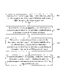
As shown in FIG. 4, an embodiment of the present invention provides a protocol
conversion
method, including the following steps.
401. A protocol conversion apparatus implements frequency synchronization and
time
synchronization with a new BBU by using the Ethernet protocol.
The protocol conversion apparatus may implement the frequency synchronization
and the time
synchronization with the new BBU by using the Synchronization Ethernet
(Synchronization
Ethernet, SyncE) protocol and IEEE 1588, or by using only IEEE 1588.
402. The protocol conversion apparatus obtains frequency synchronization
information and
time synchronization information from an Ethernet interface.
403. The protocol conversion apparatus converts the frequency synchronization
information
and the time synchronization information into frequency synchronization
information and time
synchronization information that are in a CPRI protocol format.
The protocol conversion apparatus converts, according to the CPR1 protocol,
the obtained
frequency synchronization information and time synchronization information
into the frequency
synchronization information and the time synchronization information that are
expected by a
conventional RRU.
404. The protocol conversion apparatus sends the converted frequency
synchronization
information and time synchronization information to a conventional RRU by
using a CPRI
interface.
The frequency synchronization information may be carried in a physical laver
signal, and the
conventional RRU can implement the frequency synchronization without parsing a
CPRI frame.
The time synchronization information may be carried in the CPRI frame.
In the foregoing embodiment, a protocol conversion apparatus converts
synchronization
information in an Ethernet protocol format into synchronization information in
a CPRI protocol
format and sends the synchronization information in the CPR' protocol format
to a conventional
RRU, so that the conventional RRU implements synchronization with a new BRU.
As shown in FIG 5, an embodiment of the present invention provides another
protocol
conversion method, including the following steps:
501. A protocol conversion apparatus scans, in a CPRI protocol topology
scanning manner, a
conventional RRU connected to the protocol conversion apparatus, to obtain
topology information
of the conventional RRU.
502. The protocol conversion apparatus reports the topology information to a
new BBU
8
CA 02992112 2019-01-11
according to the Ethernet protocol.
In the foregoing embodiment, a protocol conversion apparatus reports topology
information of
a conventional RRU to a new BBU by using an Ethernet message, so that the new
BBU can identify
the conventional RRU according to the topology information.
The following uses an example in which a protocol conversion apparatus is
integrated into a
new RRU, to describe a topology configuration method.
The new RRU may perform configuration in an RRU physical identification
manner. In a radio
frequency networking planning diagram, each new RRU is numbered, and a card
number (a label
stuck on a SIM card) of a subscriber identity module (Subscriber Identity
Module, SIM)
corresponding to each new RRU is identified. A rule for numbering RRUs is site
(site) number +
RRU number. An RRU identification code is prewritten into the SIM card. During
on-site
construction, the SIM card is inserted into a corresponding new RRU according
to a connection
diagram. During site deployment, a mapping relationship between the RRU
identification code and
the RRU number (a cabinet number, a subrack number, and a slot number) is
downloaded on a
network management platform to a base station, and the base station configures
data according to
the RRU number.
An example of a command for configuring a new RRU is as follows:
ADD RRU (RRU address): CN (cabinet number) = 0, SRN (subrack number) = 60, SN
(slot
number) = 0, PHYID (physical identifier) = xxxx;
The physical identifier is an RRU identification code.
A topology location of a conventional RRU based on the new RRU is configured
in a
conventional configuration manner of branch chain/ring + HOP number. That is,
a relative topology
location of the conventional RRU is configured based on the new RRU. A
conventional RRU chain
is first configured based on a new RRU node location, and then the
conventional RRU is configured
on the chain.
An example of commands for configuring a conventional RRU is as follows:
ADD RRUCIIAIN (RRU chain/ring address): RCN (chain/ring number) = I, TT
(chain/ring
type) = CHAIN, HCN (cabinet number) = 0. EISRN (subrack number) = 60, HSN
(slot number) = 0,
and HPN (port number) = 0;
ADD RRU (RRU address): CN (cabinet number) = 0, SRN (subrack number) = 61, SN
(slot
number) = 0, TP (trunk or branch) ¨ BRANCH, RCN (chain/ring number) = I, PS
(Hop number) =
0.
A new RRU scans topology information of a conventional RRU chain/ring
connected to the
new RRU in a CPR1 protocol topology scanning manner, and reports the topology
information to a
9
CA 02992112 2019-01-11
new BBU according to an Ethernet protocol format, so that the new BBU can
identify the
conventional RRU according to a branch chain/ring configuration.
An embodiment of the present invention provides another protocol conversion
method, which
mainly relates to processing of a control and management C&M packet. The CPRI
protocol defines
two control and management C&M channels: a slow C&M channel and a fast C&M
channel. The
following description is separately made by using two cases.
As shown in FIG. 6, FIG. 6 shows a protocol conversion method according to an
embodiment
of the present invention. The method, with respect to a case in which a slow
C&M channel exists
between a protocol conversion apparatus and a conventional RRU, includes the
following steps:
601. The protocol conversion apparatus allocates an FIDLC address to the
conventional RRU.
602. The protocol conversion apparatus initiates a dynamic host configuration
protocol
(Dynamic Host Configuration Protocol, DHCP) request on behalf of the
conventional RRU to
obtain an Internet Protocol (Internet Protocol, IP) address of the
conventional RRU, and establishes
a mapping relationship between the IP address and the HDLC address.
603. The protocol conversion apparatus identifies, according to the mapping
relationship
between the IP address and the HDLC address, a C&M packet sent by a new BBU to
the
conventional RRU, converts the packet into an HDLC packet, encapsulates the
HDI,C packet into a
CPRI frame, and sends the CPRI frame to the conventional RRU.
Step 603 is a downlink operation performed by the protocol conversion
apparatus on the C&M
packet. In uplink, the method further includes the following step:
604. The protocol conversion apparatus receives a CPRI frame from the
conventional RRU,
obtains an HDLC packet from the CPRI frame, converts the HDI,C packet into an
Ethernet protocol
packet, and sends the Ethernet protocol packet to the new BBU.
As shown in FIG. 7, FIG. 7 shows a protocol conversion method according to an
embodiment
of the present invention. The method, with respect to a case in which a fast
C&M channel exists
between a protocol conversion apparatus and a conventional RRU, includes the
following steps:
701. The protocol conversion apparatus identifies an Ethernet protocol C&M
packet sent by a
new BBU to the conventional RR(J.
702. The protocol conversion apparatus encapsulates the Ethernet protocol C&M
packet into a
CPRI frame, and sends the CPRI frame to the conventional RRU.
The foregoing step 701 and step 702 are downlink operations performed by the
protocol
conversion apparatus on the C&M packet. In uplink, the method further includes
the following
steps:
703. The protocol conversion apparatus receives a CPRI frame sent by the
conventional RRU,
I()
CA 02992112 2019-01-11
and parses out an Ethernet protocol C&M packet from the CPRI frame.
704. The protocol conversion apparatus sends the Ethernet protocol C&M packet
to the new
BBU.
When the fast C&M channel exists between the protocol conversion apparatus and
the
conventional RRU, the C&M packet is based on the Ethernet protocol. Therefore,
the conventional
RRU does not need to re-apply for an IP address, the IP address may be used to
identify the
conventional RRU, and the protocol conversion apparatus needs only to perform
CPRI framing and
deframing of the C&M packet.
In the foregoing embodiment, a protocol conversion apparatus performs protocol
conversion
on a C&M packet, so that a new BBU exchanges control and maintenance plane
data with a
conventional RRU.
As shown in FIG. 8, an embodiment of the present invention provides another
protocol
conversion method, including the following steps.
801. A protocol conversion apparatus receives, from a new BBU, at least one
Ethernet protocol
packet carrying user plane data, and identifies, according to a destination IP
address carried in the
Ethernet protocol packet, an Ethernet protocol packet sent to a conventional
RRU.
When sending the user plane data to the conventional RRU, the new BBU needs to
add the
user plane data to the one or more Ethernet protocol packets. The Ethernet
protocol packet carries
the destination IP address corresponding to the conventional RRU.
802. The protocol conversion apparatus extracts a valid payload (payload) from
the Ethernet
protocol packet sent to the conventional RRU, performs format conversion on
the valid payload
according to a CPRI frame format requirement, adds, to a CPR' frame, the valid
payload obtained
after the format conversion, and sends the CPRI frame to the conventional RRU.
After the protocol conversion apparatus extracts the valid payload, the CPRI
protocol has a
format requirement on IQ data in the CPRI frame. Therefore, format conversion
needs to be first
performed on the valid payload according to the format requirement, and the
valid payload can then
be carried in the CPRI frame. Step 801 and step 802 are downlink operations
performed by the
protocol conversion apparatus on the user plane data. In uplink, the method
further includes the
following steps:
803. The protocol conversion apparatus receives a CPRI frame from the
conventional RRU,
and extracts a valid payload from the CPRI frame.
804. The protocol conversion apparatus adds the valid payload to at least one
Ethernet protocol
packet, and sends the Ethernet protocol packet to the new BBU.
In the foregoing embodiment, a protocol conversion apparatus performs protocol
conversion
11
on user plane data, so that a new BBU exchanges the user plane data with a
conventional RRU.
As shown in FIG. 9, an embodiment of the present invention provides another
protocol
conversion method, including the following steps:
901. A protocol conversion apparatus obtains a delay from a new BBU to the
protocol
conversion apparatus according to the Ethernet protocol.
902. The protocol conversion apparatus obtains a delay from the protocol
conversion apparatus
to a conventional RRU according to the CPRI protocol.
903. The protocol conversion apparatus obtains a processing delay of
conversion from the
Ethernet protocol into the CPRI protocol.
904. The protocol conversion apparatus adds up the three delays to obtain an
end-to-end delay
from the new BBU to the conventional RRU, and reports the end-to-end delay to
the new BBU.
In the foregoing embodiment, for locations at which a delay Delayl from the
new BBU to the
protocol conversion apparatus, a delay Delay2 from the protocol conversion
apparatus to the
conventional RRU, and a processing delay Delay3 of conversion from the
Ethernet protocol into the
CPRI protocol are generated, refer to a networking structure diagram shown in
FIG 10. The
networking structure shown in FIG 10 is also applicable to another embodiment.
In the Ethernet
protocol, main steps of a delay measurement method are as follows: The
protocol conversion
apparatus first implements synchronization with the new BBU, and adds a time
stamp to a service
packet; after the service packet arrives at a peer end, the time stamp in the
service packet is
subtracted from time of the peer end, to obtain a delay from the protocol
conversion apparatus to the
new 1313U. In the CPRI protocol, main steps of a delay measurement method are
as follows: After
synchronization between the protocol conversion apparatus and the conventional
RRU is
implemented, a loopback method is used to measure a delay between the protocol
conversion
apparatus and the conventional RRU.
In the foregoing embodiment, a protocol conversion apparatus calculates an end-
to-end delay
from a new BBU to a conventional RRU, and reports the end-to-end delay to the
new BBU, to
facilitate subsequent radio service processing by the new BBU.
In this embodiment of the present invention, the end-to-end delay may be
measured by another
network element or another apparatus.
In this embodiment of the present invention, the protocol conversion apparatus
may further
identify an Ethernet interface or a CPRI interface.
Embodiments of the present invention further provide an apparatus embodiment
for
performing the foregoing protocol conversion method. For specific method
steps, a principle, a
technical effect, and the like, refer to the foregoing method embodiments, and
details are not
12
CA 2992112 2019-05-03
CA 02992112 2019-01-11
described in the follovving.
As shown in FIG. 11. an embodiment of the present invention provides a
protocol conversion
apparatus, including a first transceiver unit 11 I, a processing unit 112, and
a second transceiver unit
113.
The first transceiver unit 1 l 1 is configured to connect to a new BBU by
using an Ethernet
interface.
The processing unit 112 is configured to: implement frequency synchronization
and time
synchronization with the new BBU by using the Ethernet protocol, obtain
frequency
synchronization information and time synchronization information from the
Ethernet interface, and
convert the frequency synchronization information and the time synchronization
information into
frequency synchronization information and time synchronization information
that are in a common
public radio interface CPRI protocol format.
The second transceiver unit 113 is configured to send the converted frequency
synchronization
information and time synchronization information to a conventional RRU by
using a CPRI
interface.
It should be noted that in this embodiment of the present invention, the first
transceiver unit
may not be directly connected to the new BBU, and another device, for example,
a new RRU, may
exist between the protocol conversion apparatus and the new BBU.
Optionally, in this embodiment of the present invention, the processing unit
112 is further
configured to: scan the conventional RRU in a CPRI protocol topology scanning
manner to obtain
topology information of the conventional RRU, and report the topology
information to the new
BBU according to the Ethernet protocol by using the first transceiver unit
111.
Optionally, in this embodiment of the present invention, when a slow C&M
channel exists
between the protocol conversion apparatus and the conventional RRIJ, in
downlink,
the processing unit 112 is further configured to: allocate a high-level data
link control HDLC
address to the conventional RRU, initiate a dynamic host configuration
protocol DHCP request on
behalf of the conventional RRU to obtain an Internet Protocol IP address of
the conventional RRU,
establish a mapping relationship between the IP address and the IIDLC address,
identify. according
to the mapping relationship between the IP address and the HDLC address, a
control and
management packet sent by the new BRU to the conventional RRU, convert the
control and
management packet into an HDLC packet, and encapsulate the HDLC packet into a
CPRI frame;
and
the second transceiver unit 113 is further configured to send the CPRI frame
to the
conventional RRU.
13
CA 02992112 2019-01-11
Optionally, in this embodiment of the present invention, in uplink,
the second transceiver unit 113 is further configured to receive a CPRI frame
from the
conventional RRU;
the processing unit 112 is further configured to: obtain an HDLC packet from
the CPRI frame,
and convert the FIDEC packet into an Ethernet protocol packet; and
the first transceiver unit I 1 1 is further configured to send the Ethernet
protocol packet to the
new BBU.
Optionally, in this embodiment of the present invention, when a fast C&M
channel exists
between the protocol conversion apparatus and the conventional RRU. in
downlink,
the processing unit 112 is further configured to: identify an Ethernet
protocol control and
management packet sent by the new BBU to the conventional RRU, and encapsulate
the Ethernet
control and management packet into a CPRI frame; and
the second transceiver unit 113 is further configured to send the CPRI frame
to the
conventional RRU.
Optionally, in this embodiment of the present invention, in uplink,
the second transceiver unit 113 is further configured to receive a CPRI frame
sent by the
conventional RRU;
the processing unit 112 is further configured to parse out an Ethernet
protocol control and
management packet from the CPRI frame; and
the first transceiver unit 1 1 l is further configured to send the Ethernet
protocol control and
management packet to the new BBU.
Optionally, in this embodiment of the present invention, with respect to user
plane data, in
downlink,
the first transceiver unit 1 l 1 is further configured to receive, from the
new BB11, at least one
Ethernet protocol packet carrying the user plane data;
the processing unit 112 is further configured to: identify, according to a
destination IP address
carried in the Ethernet protocol packet, an Ethernet protocol packet sent to
the conventional RRU,
extract a valid payload from the Ethernet protocol packet sent to the
conventional RRU, perform
format conversion on the valid payload according to a CPRI protocol frame
format requirement,
and add, to a CPRI frame, the valid payload obtained after the format
conversion; and
the second transceiver unit 113 is further configured to send the CPRI frame
to the
conventional RRU.
Optionally, in this embodiment of the present invention, in uplink,
the second transceiver unit 113 is further configured to receive a CPRI frame
from the
14
CA 02992112 2019-01-11
conventional RRU:
the processing unit 112 is further configured to: extract a valid payload from
the CPRI frame,
and add the valid payload to at least one Ethernet protocol packet; and
the first transceiver unit Ill is further configured to send the Ethernet
protocol packet to the
new BBU.
Optionally, in this embodiment of the present invention, the processing unit
112 is further
configured to: obtain a delay from the new BBU to the protocol conversion
apparatus according to
the Ethernet protocol; obtain a delay from the protocol conversion apparatus
to the conventional
RRU according to the CPRI protocol: obtain a processing delay of conversion
from the Ethernet
protocol into the CPRI protocol: add up the delay from the new BBU to the
protocol conversion
apparatus, the delay from the protocol conversion apparatus to the
conventional RRU, and the
processing delay of conversion from the Ethernet protocol into the CPRI
protocol, to obtain an
end-to-end delay from the new BBU to the conventional RRU.
The first transceiver unit Ill is further configured to report the end-to-end
delay to the new
BBLJ.
It should be noted that, during specific product implementation, the first
transceiver unit may
be a transceiver, the second transceiver unit may be another transceiver, and
the processing unit may
be a processor. The protocol conversion apparatus may be one or more chips.
The processor may
implement a function of the processing unit by invoking an instruction stored
in a memory.
Optionally, in this embodiment of the present invention, the protocol
conversion apparatus may
be an independent device, and a networking structure may be shown in FIG. 10,
or the protocol
conversion apparatus may be integrated into a BBU or an RRU.
With descriptions of the foregoing embodiments, a person skilled in the art
may clearly
understand that the present invention may be implemented by hardware, firmware
or a combination
thereof. When the present invention is implemented by software, the foregoing
functions may be
stored in a computer-readable medium or transmitted as one or more
instructions or code in the
computer-readable medium. The computer-readable medium includes a computer
storage medium
and a communications medium. The communications medium includes any medium
that enables a
computer program to be transmitted from one place to another. The storage
medium may be any
available medium accessible to a computer. The following provides an example
but does not impose
a limitation: The computer-readable medium may include a RAM, a ROM, an
EEPROM, a
CD-ROM, or another optical disc storage or disk storage medium, or another
magnetic storage
device, or any other medium that can carry or store expected program code in a
form of an
instruction or a data structure and can be accessed by a computer. In
addition, any connection may
be appropriately defined as a computer-readable medium. For example, if
software is transmitted
from a website, a server or another remote source by using a coaxial cable, an
optical fiber/cable, a
twisted pair, a digital subscriber line (DSL) or wireless technologies such as
infrared ray, radio and
microwave, the coaxial cable, optical fiber/cable, twisted pair, DSL or
wireless technologies such as
infrared ray, radio and microwave are included in fixation of a medium to
which they belong. For
example, a disk (Disk) and disc (disc) used by the present invention includes
a compact disc CD, a
laser disc, an optical disc, a digital versatile disc (DVD), a floppy disk,
and a Blu-ray disc. Usually,
the disk copies data by a magnetic means, and the disc copies data optically
by a laser means. The
foregoing combination should also be included in the protection scope of the
computer-readable
medium.
In summary, what is described above is merely example embodiments of the
technical
solutions of the present invention, but is not intended to limit the
protection scope of the present
invention. Any modification, equivalent replacement, or improvement made
without departing from
the principle of the present invention shall fall within the protection scope
of the present invention.
16
CA 2992112 2019-05-03