Note: Descriptions are shown in the official language in which they were submitted.
CA 02992412 2018-01-12
DESCRIPTION
Title of Invention: RAISING/LOWERING CONVEYANCE DEVICE FOR
CONTAINER FOR CONVEYING ARTICLE
Technical Field
[0001] The present invention relates to a raising/lowering conveyance device
for a
container for conveying an article which includes at least two sets of
container
gripping means that grip, from both sides, the container for conveying an
article so
as to raise and lower the container.
Background Art
[0002] As this type of raising/lowering conveyance device for a container for
conveying an article, a device has been known in which, in a case where the
container for conveying an article to be handled is a large container with an
open/close door provided on its front side, as described in Patent Literature
1, a
raising/lowering member suspended from a ceiling traveling crane type
traveling
body so as to be freely raised and lowered is provided, and in which a fitting
to be
engaged provided on the ceiling surface of the large container or a hook
freely
attachable and detachable with respect to a gap below the bottom surface of
the
large container is provided on the lower side of the raising/lowering member
so
that the large container can be suspended on the lower side of the
raising/lowering
member. On the other hand, the present applicant has previously filed a
raising/lowering conveyance device for a container for conveying an article
which
is suitable for a case of conveying a plastic small container with an upper
side
opened that can be conveyed while lifted and carried with both hands (Japanese
Published Unexamined Patent Application No. 2016-3069). The raising/lowering
conveyance device for a container for conveying an article according to this
1
CA 02992412 2018-01-12
previous patent application includes at least two sets of container gripping
means
which are capable of freely moving closer to and away from the container for
conveying an article in a horizontal direction and which are freely raised and
lowered. The container gripping means have a configuration in which, on a side
where the container is present, multiple container support pins are arranged
so as
to be capable of freely protruding and retracting in the horizontal direction
and are
biased and held in a protrusion position. The raising/lowering conveyance
device
for a container for conveying an article is configured such that the container
gripping means, by the container support pins entering the lower side of an
overhanging rib overhung horizontally outward from the outside surface of the
container by movement toward the container, the container is supported.
In the raising/lowering conveyance device for a container for conveying an
article according to the previous patent application described above, a fixed
height
of a columnar support member which supports a container gripping means so as
to
raise and lower the container gripping means is assumed to be a lower limit
position, the container gripping means is supported to the columnar support
member so as to be freely raised and lowered, in a state where the container
gripping means is supported with respect to the columnar support member at the
lower limit height, the container gripped by the container gripping means is
conveyed to an area directly above an intended position, then, when the
columnar
support member is lowered to lower the gripped container to the intended
position,
the columnar support member is lowered by a fixed height, for example, about 5
to
10 mm in addition to the intended container lowering height, and the container
gripping means supported at the lower limit height on the columnar support
member is thereby brought into a vertically free state. The container is
thereby
2
CA 02992412 2018-01-12
reliably lowered on the floor surface of a storage area or the bottom portion
of the
container to be lowered is reliably fitted into an opening portion of a
container
previously placed on the floor surface of the storage area so as to lower the
container.
Citation List
Patent Literature
[0003] Patent Literature 1: Japanese Published Unexamined Patent Application
No.
H6-115608
Summary of Invention
Technical Problem
[0004] However, in the configuration described above, when, in order for the
container to be conveyed to be gripped by the container gripping means, the
container support pins of the container gripping means are made to enter the
lower
side of the overhanging rib of the container, and the container support pins
entering the upper side of the overhanging rib are in a state where the pins
are
pushed up by the overhanging rib, the weight of the entire container gripping
means acts as a load on the container support pins riding on the overhanging
rib.
By contrast, when the container support pins entering directly below the
overhanging rib are in a state where the pins are pushed down by the
overhanging
rib, the weight of the container side acts as a load on the container support
pins
entering the lower side of the overhanging rib. In either case, a
significantly large
frictional resistance is exerted between the overhanging rib and the container
support pins which make slidable contact with any one of the upper and lower
surfaces thereof, and thus the container support pins are brought into a state
where
the pins are prevented from being lightly and smoothly removed and fitted. In
3
CA 02992412 2018-01-12
particular, when, after the transfer of the container, the container support
pins of
the container gripping means are pulled out from the overhanging rib of the
container laterally outward, due to the fact that the frictional resistance
therebetween is large, there is a possibility that the container is caught
laterally
outward and the position is displaced.
Solution to Problem
[0005] The present invention proposes a raising/lowering conveyance device for
a
container for conveying an article which can solve the conventional problems
described above, and in order to easily understand a relationship with an
embodiment which will be described later, reference signs used in the
description
of the embodiment are shown in parentheses. A raising/lowering conveyance
device for a container for conveying an article includes at least two sets of
container gripping means (2A, 2B) which are capable of freely moving closer to
and away from the container for conveying an article (1) in a horizontal
direction
and which are freely raised and lowered. The raising/lowering conveyance
device for a container for conveying an article is configured such that the
container
gripping means (2A, 2B) have a pinholder-shaped structure in which multiple
container support pins (15) that are capable of freely protruding and
retracting in
the horizontal direction on the side of the container (1) and that are biased
and held
in a protrusion position are arranged, the container (1) is supported by the
container support pins (15) which enter, by movement toward the container (1),
the
lower side of a downward facing step surface (the lower surface of an
overhanging
rib (1a)) formed outside the container (1),
it is configured such that, the container gripping means (2A, 2B) are
supported to columnar support members (6a, 6b) for raising and lowering the
4
CA 02992412 2018-01-12
container gripping means (2A, 2B) so as to be freely raised and lowered,
between
the columnar support members (6a, 6b) and the container gripping means (2A,
2B),
an elastic material (although the elastic material is a compression coil
spring (20)
in the embodiment, a tension coil spring or a rubber material in place of
these
springs can also be used) for biasing the container gripping means (2A, 2B) in
a
raising direction is interposed, the container gripping means (2A, 2B) are
held, by
an upward biasing force of the elastic material, at an equilibrium height (H3)
in
equilibrium with the weight of the container gripping means (2A, 2B) so as to
be
able to be moved vertically with the equilibrium height (H3) serving as the
center
of the movement, and when the container gripping means (2A, 28) lift the
container (1), the container gripping means (2A, 2B) which received the weight
of
the container (1) and lowered from the equilibrium height (H3) are supported
at a
fixed height of the columnar support members (6a, 6b).
Advantageous Effects of Invention
[0006] According to the configuration of the present invention described
above,
the container gripping means which is not in the state of supporting the
container
are held by the elastic material at the equilibrium height in an unstable
state in the
up/down direction. That is, since the container gripping means is in a state
where
the weight thereof is cancelled out, even with a small external force, it is
possible
to easily move the container gripping means vertically. In addition, in a
state
where the container gripping means support the container, the container
gripping
means which received the weight of the container and lowered to the height
lower
than the equilibrium height is supported at the fixed height of the columnar
support
members. Therefore, in an operation step of receiving the container to be
conveyed by the container gripping means, the empty container gripping means
5
CA 02992412 2018-01-12
held at the equilibrium height are lowered to a predetermined height beside
the
container to be conveyed together with the columnar support members, and are
then moved close to the container to be conveyed together with the columnar
support members. At this time, even in a case where, among the multiple
container support pins included in the container gripping means, a vertical
pressing
pin is present which is located at such a height as to ride on the upper
surface of
the container to be conveyed or to be pushed down by a downward facing step
surface of the container to be conveyed, the container gripping means at this
time
is in a state where the weight thereof is cancelled out by the biasing force
of the
elastic material. Therefore, according to an upward or downward force received
by the vertical pressing pin from the upper surface or the downward facing
step
surface of the container, the container gripping means themselves are lightly
and
easily moved vertically, and therefore the vertical pressing pin can ride on
the
upper surface of the container with a small frictional resistance or can enter
below
the downward facing step surface of the container with a small frictional
resistance.
[0007] In an operation step of lowering the container to be conveyed to an
intended position by the container gripping means, the container gripping
means
which received the weight of the container and lowered to the height lower
than
the equilibrium height is supported at the fixed height of the columnar
support
members, therefore, as in the conventional one, it is possible to convey the
container in a stable state. However, as described previously, in a case
where, an
operation is performed in which, in addition to the height at which the
container to
be conveyed is estimated to have reached the intended lowering height, the
container gripping means are further lowered together with the columnar
support
6
CA 02992412 2018-01-12
members by the fixed height so as to reliably lower the container to be
conveyed at
a predetermined height, after the container to be conveyed is lowered at the
predetermined position, the weight of the container to be conveyed no longer
acts
on the container gripping means, and simultaneously, the container gripping
means
receives the upward biasing force of the elastic material. Therefore, the
container
support pin which is located directly above the downward facing step surface
of
the container to be conveyed is not, unlike the conventional one, strongly
pressed
downward against the upper surface of the container to be conveyed, but the
container support pin which is located directly below the downward facing step
surface of the container to be conveyed, that is, the pin which supported the
container to be conveyed at the time of conveyance is naturally moved upward
to
such a height as to abut against the step surface by the biasing force of the
elastic
material together with the container gripping means.
[0008] Therefore, even when the operation is performed in which, in addition
to
the height at which the container to be conveyed is estimated to have reached
the
intended lowering height, the container gripping means are further lowered
together with the columnar support members by the fixed height, there does not
occur a phenomenon in which the container support pin is strongly pressed
against
the upper surface of the container to be conveyed. As a matter of course, in
the
retraction movement of the container gripping means after the container is
lowered
at the predetermined position, that is, in the operation of pulling out the
container
support pin laterally outward, even if a container support pin is present
which
abuts against the upper surface or the downward facing step surface of the
container, since the vertical pressing force acting between the pin and the
surface
on the side of the container is a force caused by the biasing force of the
elastic
7
CA 02992412 2018-01-12
material for cancelling out the weight of the container gripping means, the
frictional force acting between both of them is significantly small, the
lowered
container is therefore prevented from being dragged laterally as the container
support pin is pulled out.
[0009] In a case where the present invention is implemented, it is also
possible to
interpose the elastic material for lifting the container gripping means
between the
container gripping means and the columnar support members so as to make the
container gripping means held at the equilibrium height in equilibrium with
the
weight thereof. In this case, stoppers which receive, when the container
gripping
means support the container to be conveyed, the container gripping means
lowered
from the equilibrium height at the predetermined height are required to be
provided on the side of the columnar support members. However, preferably, in
the columnar support members (6a, 6b), spring bearing members (18) are
provided
in a position below the container gripping means (2A, 2B), and on the spring
bearing members (18), as the elastic material, a plurality of compression coil
springs (20) for supporting the container gripping means (2A, 2B) at upper
ends
thereof are attached. According to this configuration, it is possible to
enhance the
stability of the container gripping means at the equilibrium height.
[0010] In a case where the container gripping means are supported by the
compression coil springs as described above, the container gripping means
which
support and lower the container to be conveyed can also be supported by the
upper
ends of the compression coil springs that received the weight of the container
and
is compressed to a compression limit. However, preferably, stoppers (21a, 21b)
are separately provided which receive, in a position higher than the height of
the
upper ends at the time of maximum compression of the compression coil springs
8
CA 02992412 2018-01-12
(20), the container gripping means (2A, 2B) that are lowered from the
equilibrium
height (H3). According to this configuration, it is possible to enhance the
durability of the compression coil springs used, to enhance the accuracy of
the
lowering limit height of the container gripping means which supported the
container to be conveyed, and to stably support the container gripping means.
Furthermore, although the compression coil spring which is cylindrical with
the
same diameter from the lower end to the upper end may be used, the compression
coil spring is preferably used which is formed in the shape of a cone in which
the
upper end for supporting the container gripping means (2A, 2B) has the minimum
diameter. According to this configuration, the spring itself has the function
of
automatically aligning the upper end (the upper end having the minimum
diameter),
it is therefore possible to make the raising/lowering movement of the
container
gripping means (2A, 2B) with respect to the columnar support members (6a, 6b)
smoothly performed. Moreover, as compared with the cylindrical compression
coil spring, it is also possible to significantly decrease the the minimum
length at
the compression limit with respect to the maximum length at the time of no
load, it
is therefore possible to easily increase the amount of lowering of the
container
gripping means from the equilibrium height.
Brief Description of Drawings
[0011] [Fig. 1] Fig. 1 is a plan view showing a gripping device which is in an
open
state with respect to a container to be conveyed.
[Fig. 2] Fig. 2 is a plan view showing the gripping device which is in a
closed state
with respect to the container to be conveyed.
[Fig. 3] Fig. 3 is a side view showing a main portion of the gripping device
including upper/lower two-stacked container gripping means.
9
CA 02992412 2018-01-12
[Fig. 4] Fig. 4A is a front view of a main portion showing the lower container
gripping means, Fig. 4B is a transverse sectional plan view in a position
directly
above the lower container gripping means, and Fig. 4C is a transverse
sectional
plan view in a position directly below the lower container gripping means.
[Fig. 5] Fig. 5A is a front view of a main portion showing the upper container
gripping means, and Fig. 5B is a transverse sectional plan view in a position
directly below the upper container gripping means.
[Fig. 6] Fig. 6 is a side view of a main portion showing how the gripping
device
shown in Fig. 3 grips the container.
[Fig. 7] Fig. 7A is a longitudinal sectional side view of a main portion
showing a
state where the container gripping means lifts the container, and Fig. 7B is
an
enlarged longitudinal sectional side view of a main portion showing the
internal
structure of the container gripping means.
[Fig. 8] Figs. 8A to 8C are partially longitudinal sectional side views of a
main
portion illustrating the detailed structure and the action of a spring
supporting the
container gripping means.
Description of Embodiments
[0012] A raising/lowering conveyance device for a container for conveying an
article according to the present embodiment shown in attached figures has the
same basic structure as that shown in the description and drawings of the
previously described previous patent application invention (the invention
disclosed
in Japanese Published Unexamined Patent Application No. 2016-3069), as shown
in Figs. 1 to 3, the device lifts and conveys a plastic container for
conveying an
article which is small enough to be able to be lifted and carried with both
hands,
and which can be stacked (hereinafter referred to as a container in short) 1.
The
CA 02992412 2018-01-12
raising/lowering conveyance device includes a pair of container gripping means
2A and 2B which grip both sides of the container 1 placed in a center position
CP
parallel to a horizontally vertical direction imaginary line X of the
horizontally
vertical direction imaginary line X and a horizontally lateral direction
imaginary
line Y which pass through the center position CP in the plan view of the
raising/lowering conveyance device and which are perpendicular to each other,
and
four positioning members 3a to 4b which are fitted to the four corners of the
container 1 for positioning. A description will be given below with the
assumption that a direction parallel to the horizontally vertical direction
imaginary
line X is a horizontally vertical direction and that a direction parallel to
the
horizontally lateral direction imaginary line Y is a horizontally lateral
direction.
[0013] Above the horizontally lateral direction pair of container gripping
means
2A and 2B, laterally moving bases 5A and 5B are provided which are formed with
horizontal members that are long in the horizontally vertical direction and
which
are capable of freely moving closer to and away from each other in the
horizontally lateral direction while keeping symmetrical positions with
respect to
the horizontally vertical direction imaginary line X. To the inner sides of
the
centers of the laterally moving bases 5A and 5B intersecting the horizontally
lateral direction imaginary line Y, columnar support members 6a and 6b are
attached so as to be freely raised and lowered. The container gripping means
2A
and 2B are attached to the inner sides of the respective columnar support
members
6a and 6b at the same height. Movable bases 7a to 8b are supported to both end
portions of the respective laterally moving bases 5A and 5B in the length
direction
thereof so as to be capable of freely moving closer to and away from each
other in
the horizontally vertical direction while keeping symmetrical positions with
11
CA 02992412 2018-01-12
respect to the horizontally lateral direction imaginary line Y, and the
respective
positioning members 3a to 4b are supported to the respective movable bases 7a
to
8b so as to be freely raised and lowered. Each of the positioning members 3a
to
4b is formed with a mold member whose transverse section is formed in the
shape
of the letter L in a direction which is able to be fitted to the four corners
of the
container 1 and which is long in a vertical up/down direction.
[0014] According to the configuration described above, by moving both the
laterally moving bases 5A and 58 close to each other in the horizontally
lateral
direction, and simultaneously moving the respective movable bases 7a, 7b, 8a,
and
8b close to each other in the horizontally vertical direction with respect to
the
respective laterally moving bases 5A and 5B, as shown in Fig. 2, the center
portions of both the sides of the container 1 in the horizontally lateral
direction can
be gripped by the horizontally lateral direction pair of container gripping
means
2A and 2B, and simultaneously, the respective positioning members 3a to 4b can
be fitted to the four corners of the container 1. Both the laterally moving
bases
5A and 5B are supported at a fixed height above the floor surface of a
container
storage area on a conveyance carriage capable of traveling in the horizontally
vertical direction and the horizontally lateral direction, and the columnar
support
members 6a and 6b to which the container gripping means 2A and 2B are
respectively attached are individually driven via two raising/lowering driving
flat
belts 10a and 10b with respect to the respective laterally moving bases 5A and
5B.
The lower ends of these respective two raising/lowering driving flat belts 10a
and
10b are coupled to both end portions of horizontal members 9 which are
attached
to the lower ends of the columnar support members 6a and 6b so as to be
overhung
to both sides in the horizontally vertical direction. The positioning members
3a
12
CA 02992412 2018-01-12
and 3b perform raising/lowering movement with respect to the respective
movable
bases 7a and 7b in synchronization with the raising/lowering movement of the
columnar support member 6a located in the intermediate position thereof, and
the
positioning members 4a and 4b perform raising/lowering movement with respect
to the respective movable bases 8a and 8b in synchronization with the
raising/lowering movement of the columnar support member 6b located in the
intermediate position thereof.
[0015] The horizontally lateral direction pair of container gripping means 2A
and
2B include lower single members 11 which are attached to the lower end
portions
of the columnar support members 6a and 6b, and upper single members 12 which
are attached to the columnar support members 6a and 6b at positions upward
away
from the lower single members 11 by an appropriate distance, and the
respective
single members 11 and 12 have the same structure and include, as shown in
Figs. 1
and 2, parallel casings 1 la to 12b which are arranged on both sides of the
columnar support members 6a and 6b and which are vertically long. Between the
parallel casings 1 la and 1 lb and between the parallel casings 12a and 12b, a
pair
of upper and lower guide blocks 14 are attached which are fitted to
raising/lowering guide rails 13 provided on the inner sides of the columnar
support
members 6a and 6b so as to be freely raised and lowered, and the lower single
members 11 and the upper single members 12 are thereby freely raised and
lowered with respect to the columnar support members 6a and 6b. Container
support pins 15 are individually supported to the casings 11 a to 12b in plan
view in
symmetrical positions with respect to the horizontally lateral direction
imaginary
line Y in two rows vertically.
[0016] These container support pins 15 are arranged, as shown in Figs. 4A and
5A,
13
CA 02992412 2018-01-12
such that when seen from a front view from the side of the center position CP,
two
container support pins 15 of the same height with a narrow distance in the
horizontally vertical direction and two container support pins 15 of the same
height
with a wide distance in the horizontally vertical direction are alternately
located in
the up/down direction an appropriate distance apart from each other. As shown
in Fig. 7B, in each of the container support pins 15, a container support tip
end
portion 15a which is protruded from the casings 1 1 a to 12b is processed so
as to be
tapered, the container support pin 15 includes a stopper 15b which abuts
against
the inner side of the front side wall plate of the casings 1 1 a to 12b and
the rear end
thereof has such a length as to penetrate the rear side wall plate of the
casings 11a
to 12b. Each of the container support pins 15 is biased and held by a
compression
coil spring 15c loosely fitted to the container support pin 15 between the
stopper
15b and the rear side wall plate of the casings 1 1 a to 12b into a state
where the
container support tip end portion 15a is protruded a predetermined length from
the
casings lla to 12b.
[0017] As shown in Figs. 3 to 5B, in the lower single members 11 and the upper
single members 12 of the container gripping means 2A and 2B configured as
described above, the lower ends thereof are supported via support means 16 and
17
to the columnar support members 6a and 6b. The respective upper and lower
support means 16 and 17 are formed with spring bearing members 18 which are
attached to the columnar support members 6a and 6b, a plurality of compression
coil springs 20 which are attached via spring attachment plates 19 onto the
spring
bearing members 18, and a horizontally vertical direction pair of stoppers 21a
and
21b which are made of an elastic material. These stoppers 21a and 21b are
separately attached, on the rear side of the spring attachment plate 19, on
the
14
CA 02992412 2018-01-12
spring bearing member 18, to both the sides of the columnar support members 6a
and 6b in the horizontally vertical direction. As the spring bearing members
18
of the lower support means 16 for supporting the lower single members 11, the
horizontal members 9 which are attached to the lower ends of the columnar
support members 6a and 6b and to which the lower ends of the raising/lowering
driving flat belts 10a and 10b are coupled are utilized as they are. As shown
in
Figs. 5A and 58, the spring bearing members 18 of the upper support means 17
for
supporting the upper single members 12 are formed with horizontal plates 18a
that
have, in the center thereof, concave entrance portions into which the columnar
support members 6a and 6b and the raising/lowering guide rails 13 on the inner
sides thereof enter, and U-shaped plates 18b which are located on the lower
sides
of the horizontal plates 18a and whose upper end are fixed to the inner sides
of the
concave entrance portions. The U-shaped plates 18b are attached to the
columnar
support members 6a and 6b.
[0018] As shown in Figs. 8A to 8C, the compression coil spring 20 in each of
the
support means 16 and 17 is formed in the shape of a cone in which an upper end
ring portion 20a for receiving the bottom surface (the bottom surface of each
of the
casings 1 la to 12b) of each of the upper and lower single members 11 and 12
has
the minimum diameter. In the spring attachment plate 19, an attachment hole
19a
is provided whose inside diameter is smaller than the outside diameter of a
lower
end ring portion 20b having the maximum diameter of the compression coil
spring
20. In a state where the lower end ring portion 20b of the compression
coil spring
20 is made to enter the lower side of the attachment hole 19a, the lower end
ring
portion 20b and the spring attachment plate 19 are fixed such as by spot
welding,
and a plurality of compression coil springs 20 are thereby attached onto the
spring
CA 02992412 2018-01-12
attachment plates 19 such that the compression coil springs 20 are
appropriately
aligned, for example, as shown in Figs. 4C and 5B, four compression coil
springs
20 are aligned so as to support each of the casings 11 a to 12b. Then, the
spring
attachment plate 19 is placed on the spring bearing member 18 on the side of
the
columnar support members 6a and 6b, and in a state where the lower end ring
portions 20b of the compression coil springs 20 are sandwiched between the
spring
attachment plate 19 and the spring bearing member 18, both ends of the spring
attachment plate 19 are attached to the spring bearing member 18 with, for
example, bolts and nuts.
[0019] The conical compression coil spring 20 in each of the support means 16
and 17 is deformed by receiving a compression force, from a maximum elongation
height H1 in a no-load state shown in Fig. 8A to a height H2 at the time of
maximum compression shown in Fig. 8C. When the compression coil spring 20
is at the height H2 at the time of maximum compression shown in Fig. 8C, it is
in a
state where a small-diameter ring portion on the upper side enters the inside
of a
large-diameter ring portion on the lower side such that they abut against each
other,
and the height of the compression coil spring 20 is therefore lower than a
height
obtained by adding the diameters of the wires by the number of stacks. As a
matter of course, a conical compression coil spring can also be used in which
a
small-diameter ring portion on the upper side fully enters the inside of a
large-diameter ring portion on the lower side such that the ring portions in
all the
stacks enter, in a spiral shape, the inside of one ring portion in contact
with the
upper surface of the spring attachment plate 19.
[0020] In any case, as shown in Fig. 8C, in the compression coil spring 20,
the
height H2 at the time of maximum compression is lower than the height SH of
the
16
CA 02992412 2018-01-12
stoppers 21a and 21b attached on the same spring bearing member 18, and the
maximum elongation height H1 is sufficiently higher than the height SH of the
stoppers 21a and 21b. When the respective upper and lower single members 11
and 12 of the container gripping means 2A and 2B in the no-load state where
the
container 1 is not gripped are supported by the respective support means 16
and 17,
the individual compression coil springs 20 in each of the support means 16 and
17
are, as shown in Fig. 8B, compressed and deformed so as to have a height in
equilibrium with the weight of each of the single members 11 and 12, with the
result that the respective single members 11 and 12 are supported at an
equilibrium
height H3. The equilibrium height H3 at this time is higher than the height SH
of
the stoppers 21a and 21b. Furthermore, as will be described later, the size
and
strength of the compression coil springs 20 are set such that when the lower
single
members 11 or both the upper and lower single members 11 and 12 in the
container gripping means 2A and 2B grip and lift the predetermined container 1
via the respective container support pins 15, the lower single members 11 or
both
the upper and lower single members 11 and 12 receive the weight of the
container
1 and lower while compressing and deforming the compression coil springs 20 of
the support means 16 and 17, and the single members 11 and 12 are received by
the stoppers 21a and 21b made of the elastic material before the compression
coil
springs 20 reach the height H2 at the time of maximum compression.
[0021] As shown in Figs. 1 to 3 and 7A, the container 1, which is handled in
the
raising/lowering conveyance device configured as described above, has a
quadrangular planar shape, and the container 1 is formed in the shape of a box
with
its upper side opened, an overhanging rib 1 a that is overhung outward for
reinforcement and the formation of a handle is integrally formed around an
17
CA 02992412 2018-01-12
opening portion and a protrusion base portion lb that has such a size as to be
able
to fit the inside of an opening portion in another container 1 is integrally
formed on
the bottom portion. Therefore, in the container 1, the lower surface of the
overhanging rib la serves as a downward facing step surface, and the upper
surface of the overhanging rib la serves as the upper surface of the container
1. It
is noted that the structure of the container 1 is not limited to the structure
shown in
the figures. For example, a container may be adopted in which near the upper
end of a peripheral wall surface, a concave groove portion parallel to the
peripheral
direction is formed and in which the upper surface of the inside of the
concave
groove portion serves as a downward facing step surface.
[0022] Within the storage area of the container 1 where the raising/lowering
conveyance device configured as described above is additionally provided, the
containers 1 are arranged in a direction such that the four sides thereof are
parallel
to the horizontally vertical direction and the horizontally lateral direction.
Then,
in a case where a specific container 1 among them is conveyed from the
position to
another place, as shown in Fig. 1, the raising/lowering conveyance device is
made
to travel such that the center position CP of the raising/lowering conveyance
device matches the center position of the container 1 to be conveyed in plan
view,
and is stopped in a position directly above the container 1 to be conveyed.
Next,
in a state where the container gripping means 2A and 2B and the respective
positioning members 3a to 4b are located on the outside of the container 1 to
be
conveyed in plan view, the raising/lowering driving flat belts 10a and 10b are
driven so as to lower the horizontally lateral direction pair of columnar
support
members 6a and 6b and the four positioning members 3a to 4b, and, as shown in
Fig. 3, the lower single members 11 of the respective container gripping means
2A
18
CA 02992412 2018-01-12
and 2B and the respective positioning members 3a to 4b are located directly
beside
the overhanging rib la of the container 1 to be conveyed (directly beside the
overhanging rib la of the lowermost container 1 when, as shown in Fig. 3, a
plurality of containers 1 stacked vertically are to be conveyed). At this
time,
there is a case where the container 1 to be conveyed is multiple containers
stacked,
and the container(s) 1 to be conveyed is located also on the inner side of the
upper
single members 12 in the container gripping means 2A and 2B.
[0023] The container gripping means 2A and 2B and the respective positioning
members 3a to 4b are lowered to the predetermined height as described above,
then, the laterally moving bases 5A and 5B are moved close to each other in
the
horizontally lateral direction and the movable bases 7a to 8b on the
respective
laterally moving bases 5A and 5B are moved close to each other in the
horizontally
vertical direction, and thus, as shown in Figs. 2 and 6, the respective
positioning
members 3a to 4b are fitted to the four corners of the container 1 to be
conveyed,
and simultaneously, the container 1 to be conveyed is sandwiched from both
sides
in the horizontally lateral direction by both the container gripping means 2A
and
2B. Consequently, as shown in Figs. 6 and 7A, among the container support
pins
15 of both the upper and lower single members 11 and 12 in both the container
gripping means 2A and 2B, the tip end of the container support pin 15 at a
height
facing the overhanging rib la of the container 1 to be conveyed abuts against
the
outside surface of the overhanging rib la so as to be prevented from being
moved
forward. Therefore, the container support pin 15 is relatively retracted into
the
casings 1 1 a to 12b against the biasing force of the compression coil spring
15c,
and only the other container support pins 15 are moved close to the outside
surface
of the container 1 to be conveyed while being held in the protrusion position
by the
19
CA 02992412 2018-01-12
biasing force of the compression coil spring 15c.
[0024] As described above, in the process in which the container 1 to be
conveyed
is sandwiched from both sides in the horizontally lateral direction by both
the
container gripping means 2A and 2B that are moved closer to each other in the
horizontally lateral direction, it is highly likely that, among the container
support
pins 15 held in the positon of the protrusion by the biasing force of the
compression coil spring 15c, a container support pin 15 is present which is
moved
forward while pressing, in the up/down direction, to the upper surface or the
lower
surface of the overhanging rib la in the container 1 to be conveyed. On the
other
hand, the respective upper and lower single members 11 and 12 which support
the
container support pins 15 such that the container support pins 15 are capable
of
freely protruding and retracting are, as shown in Fig. 8B, supported by the
compression coil springs 20 of the support means 16 and 17 at the equilibrium
height H3 in equilibrium with the weight thereof and therefore are in a state
where
they are able to be moved loosely floating in the up/down direction.
[0025] Therefore, in a case where a specific container support pin 15 is
present
which is moved forward while pressing to the upper surface of the overhanging
rib
la in the container 1 to be conveyed, in combination with the fact that the
container support tip end portion 15a of each of the container support pins 15
is
formed in the shape of a tapered cone, while by a pressing reaction force in
the
up/down direction between the specific container support pin 15 and the upper
surface of the overhanging rib la in the container 1 to be conveyed, the
entire
single members 11 and 12 having the specific container support pin 15 are
being
moved upward along the columnar support members 6a and 6b in the direction in
which the upward biasing force of the compression coil springs 20 in the
support
CA 02992412 2018-01-12
means 16 and 17 act, the container support tip end portion 15a of the specific
container support pin 15 rides on the upper surface of the overhanging rib la
in the
container 1 to be conveyed so as to be able to be reliably moved to a forward
limit
position. By contrast, even in a case where a specific container support pin
15 is
present which is moved forward while pressing to the lower surface of the
overhanging rib 1 a in the container 1 to be conveyed, in combination with the
fact
that the container support tip end portion 15a of each of the container
support pins
is formed in the shape of a tapered cone, while by a pressing reaction force
in
the up/down direction between the specific container support pin 15 and the
lower
10 surface of the overhanging rib la in the container 1 to be conveyed, the
entire
single members 11 and 12 having the specific container support pin 15 are
being
moved downward along the columnar support members 6a and 6b against the
upward biasing force of the compression coil springs 20 in the support means
16
and 17, the container support tip end portion 15a of the specific container
support
15 pin 15 enters below the lower surface of the overhanging rib 1 a in the
container 1
to be conveyed so as to be able to be reliably moved to the forward limit
position.
[0026] As described above, when, as shown in Fig. 6, the container 1 to be
conveyed is sandwiched from both sides in the horizontally lateral direction
by
both the container gripping means 2A and 2B which are moved closer to each
other in the horizontally lateral direction, the raising/lowering driving flat
belts 10a
and 10b are driven in the opposite direction, so as to raise the horizontally
lateral
direction pair of columnar support members 6a and 6b and the four positioning
members 3a to 4b. Consequently, as shown in Fig. 7A, among the container
support pins 15 of both the container gripping means 2A and 2B, the container
support tip end portion 15a of an effective container support pin 15 which
enters
21
CA 02992412 2018-01-12
directly below the overhanging rib la of the container 1 to be conveyed lifts
the
container 1 to be conveyed. At this time, the weight of the container 1 to be
conveyed acts, via the effective container support pins 15, downward on the
single
members 11 and 12 having the effective container support pins 15, and the
single
members 11 and 12 are therefore lowered while further compressing and
deforming the compression coil springs 20 of the support means 16 and 17 from
the equilibrium height H3 shown in Fig. 8B and are then received by the
stoppers
21a and 21b. In other words, the weight of the container 1 to be conveyed is
reliably received by the columnar support members 6a and 6b via the effective
container support pins 15 of both the container gripping means 2A and 2B, the
single members 11 and 12 having the effective container support pins 15, and
the
stoppers 21a and 21b made of the elastic material, and thus it is possible to
stably
lift the container 1 to be conveyed. Since in the lifting described above, the
positioning members 3a to 4b are fitted to the four corners of the container 1
to be
conveyed so as to position the container 1 to be conveyed, even a plurality of
containers 1 stacked can be stably lifted and conveyed without swinging the
containers 1.
[0027] When the container 1 which is lifted and conveyed by the
raising/lowering
conveyance device in this way is lowered to another place, it suffices that
the
raising/lowering conveyance device is operated in a procedure opposite to the
operational procedure described above. However, in order for the transfer of
the
container 1 to be conveyed in the place of the lowering to be reliably
performed,
the lowering limit height of the container gripping means 2A and 2B and the
positioning members 3a to 4b is not set to the height at which the bottom
surface
of the container 1 to be conveyed suspended by the container gripping means 2A
22
CA 02992412 2018-01-12
and 2B via the effective container support pins 15 reaches the floor surface
or to
the height at which the protrusion base portion lb is fitted into the opening
portion
at the tip end of another container 1 that has already been stored but is set
to a
height that is slightly lower than such height. In such a case, when the
container
1 to be conveyed suspended via the effective container support pins 15 reaches
the
floor surface or when the protrusion base portion lb is fitted into the
opening
portion at the tip end of another container 1 so as to be supported, the
weight of the
container 1 to be conveyed is received by the floor surface or another
container
therebelow, and thus the weight no longer acts on the effective container
support
pins 15. Consequently, the single members 11 and 12 having the effective
container support pins 15 are brought into a state where they can be moved
upward
within a range from the lowering limit height at which the single members 11
and
12 are supported by the stoppers 21a and 21b to the height at which the
compression coil springs 20 are returned to the equilibrium height H3 by
receiving
the upward biasing force of the compression coil springs 20 in the support
means
16 and 17.
[0028] Therefore, after the weight of the container 1 to be conveyed is
received by
the floor surface or another container therebe low, the single members 11 and
12 of
the container gripping means 2A and 2B are not lowered as the columnar support
members 6a and 6b supporting the container gripping means 2A and 2B are
lowered, but while the height is maintained at which the effective container
support pins 15 receive the upward biasing force of the compression coil
springs
20 in the support means 16 and 17 so as to abut against the lower surface of
the
overhanging rib 1 a in the container 1 to be conveyed, only the columnar
support
members 6a and 6b are relatively lowered with respect to the container
gripping
23
CA 02992412 2018-01-12
means 2A and 2B until the compression coil springs 20 reach the equilibrium
height H3. When the lowering of the columnar support members 6a and 6b is
stopped in the process in which the compression coil springs 20 reach the
equilibrium height H3, the effective container support pins 15 are in a state
where
they are kept abutting against the lower surface of the overhanging rib la in
the
container 1 to be conveyed, a pressing force therebetween at that time is, at
the
maximum, equivalent to a compression reaction force until the compression coil
springs 20 reach the equilibrium height H3, i.e., small. In addition, when the
lowering of the columnar support members 6a and 6b is stopped after the
compression coil springs 20 reach the equilibrium height H3, the effective
container support pins 15 are separated downward from the lower surface of the
overhanging rib la in the container 1 to be conveyed, and the container
support
pins 15 located directly above the upper surface of the overhanging rib la are
lowered so as to abut against the upper surface of the overhanging rib la in
the
container 1 to be conveyed. In this case as well, the pressing force is lower
than
the biasing force of the compression coil springs 20 in equilibrium with the
weight
of the single members 11 and 12, since the single members 11 and 12 are kept
biased upward, the pressing force acting between the upper surface of the
overhanging rib la in the container 1 to be conveyed and the container support
pins 15 which abut thereagainst is lower than a force equivalent to the weight
of
the single members 11 and 12.
[0029] As described above, the container gripping means 2A and 2B and the
positioning members 3a to 4b are lowered to the lowering limit height so as to
lower the container 1 to be conveyed to an intended place, then the container
gripping means 2A and 2B are moved away from each other in the horizontally
24
CA 02992412 2018-01-12
lateral direction, the positioning members 3a to 4b are moved horizontally
away
from the four corners of the container 1 to be conveyed such that the gripping
action on the container 1 to be conveyed is cancelled and thereafter the
container
gripping means 2A and 2B and the positioning members 3a to 4b are raised to
the
original standby height, with the result that a series of container lowering
steps are
completed. When in the process of the container lowering steps, as described
above, the container gripping means 2A and 2B are moved away from each other
in the horizontally lateral direction, and thus the container support pins 15
of the
respective single members 11 and 12 are released in the horizontally lateral
direction from a region which overlaps, in plan view, the overhanging rib la
in the
container 1 to be conveyed, as described above, the pressing force between the
upper surface or the lower surface of the overhanging rib la and the container
support pins 15 which abut thereagainst is zero or small. Therefore, the pull-
out
resistance of the container support pins 15 abutting against the upper surface
or the
lower surface of the overhanging rib la is small, and even when the container
1 to
be conveyed is one container which is empty and which is not stacked, the
possibility that the container 1 to be conveyed is dragged laterally as the
container
support pins 15 are pulled out is eliminated.
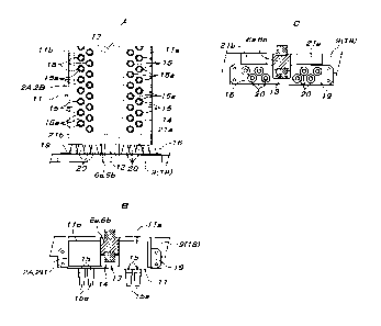
Industrial Applicability
[0030] A raising/lowering conveyance device for a container for conveying an
article according to the present invention can be utilized as a device which
is able
to, in a storage facility in which a container for conveying an article that
is small
enough to be able to be lifted with both hands is directly placed on a flat
surface,
sandwich both sides of the container with container gripping means and thereby
can lift and convey the container.
CA 02992412 2018-01-12
Reference Signs List
[0031] 1 Container
la Overhanging rib (step surface where lower surface faces downward)
2A, 2B Container gripping means
3a to 4b Positioning member
5A, 5B Laterally moving base
6a, 6b Columnar support member
7a to 8b Movable base
10a, 10b Raising/lowering driving flat belt
11 Lower single member
, lla to 12b Casing
12 Upper single member
13 Raising/lowering guide rail
14 Guide block
15 Container support pin
15a Container support tip end portion
15b Stopper
15c Compression coil spring
16, 17 Support means
18 Spring bearing member
19 Spring attachment plate
20 Compression coil spring
21a, 21b Stopper made of elastic material
CP Center position of raising/lowering conveyance device
H1 Maximum elongation height of compression coil spring
26
CA 02992412 2018-01-12
H2 Height at the time of maximum compression of compression coil
spring
H3 Equilibrium height where single member in no-load state is
supported
X Horizontally vertical direction imaginary line
Y Horizontally lateral direction imaginary line
27