Note: Descriptions are shown in the official language in which they were submitted.
ROTATING STAGE COLLAR
FIELD OF DISCLOSURE
[0001] The present disclosure relates generally to the field of well
drilling operations. More
specifically, embodiments of the present disclosure relate to rotating stage
collars for use with
casing and cementing in a down-hole environment.
BACKGROUND
[0002] In conventional oil and gas operations, a well is typically drilled
to a desired depth
with a drill string, which includes drill pipe and a drilling bottom hole
assembly (BHA). Once
the desired depth is reached, the drill string is removed from the hole and
casing is run into the
vacant hole. In some conventional operations, the casing may be installed as
part of the drilling
process. A technique that involves running casing at the same time the well is
being drilled may
be referred to as "casing-while-drilling."
[0003] Casing may be defined as pipe or tubular that is placed in a well to
prevent the well
from caving in, to contain fluids, and to assist with efficient extraction of
product. When the
casing is properly positioned within a hole or well, the casing is typically
cemented in place by
pumping cement through the casing and into an annulus formed between the
casing and the hole
(e.g., a wellbore or parent casing). As the cement is pumped through the
casing and into the
annulus, the casing may be rotated within the wellbore to help facilitate
proper migration and
settling of the casing within the annulus. Once a casing string has been
positioned and cemented
in place or installed, the process may be repeated via the now installed
casing string. For
example, the well may be drilled further by passing a drilling BHA through the
installed casing
string and drilling. Further, additional casing strings may be subsequently
passed through the
installed casing string (during or after drilling) for installation. Indeed,
numerous levels of
casing may be employed in a well, with each level having multiple stages. For
example, once a
first string of casing is in place, the well may be drilled further and
another string of casing (an
inner string of casing) with an outside diameter that is accommodated by the
inside diameter of
the previously installed casing may be run through the existing casing.
Additional strings of
1
CA 2992609 2018-01-23
casing may be added in this manner such that numerous concentric strings of
casing are
positioned in the well, and such that each inner string of casing extends
deeper than the
previously installed casing or parent casing string.
BRIEF DESCRIPTION
[0004] In a first embodiment, a system includes a rotating stage collar
having an upper collar
configured to couple to a first length of tubular, a lower collar configured
to couple to a second
length of tubular, and an inner sleeve disposed within the upper collar and
the lower collar,
wherein the upper collar and the lower collar are rotationally fixed to one
another when the inner
sleeve is in a first position within the upper collar and the lower collar,
wherein the upper collar
and the lower collar are rotationally independent of one another when the
inner sleeve is in a
second position within the upper collar and the lower collar, and wherein the
second position is
axially beneath the first position relative to a longitudinal axis of the
rotating stage collar when
the rotating stage collar is positioned within a wellbore.
[0005] In a second embodiment, a system includes a first tubular configured
to be secured
within a wellbore, a second tubular configured to be secured within the
wellbore, and a rotating
stage collar. The rotating stage collar includes an upper collar coupled to
the first tubular, a
lower collar coupled to the second tubular, a load nut disposed radially about
the upper collar
and threaded to the lower collar, and an inner sleeve disposed within the
upper collar and the
lower collar, wherein the upper collar and the lower collar are rotationally
fixed relative to one
another when the inner sleeve is in a first position within the upper collar
and the lower collar,
and the upper collar and lower collar are rotationally independent of one
another when the inner
sleeve is in a second position within the upper collar and the lower collar,
and wherein the
second position is axially beneath the first position relative to a
longitudinal axis of the rotating
stage collar when the rotating stage collar is positioned within the wellbore.
[0006] In a third embodiment, a method includes coupling a lower collar of
a rotating stage
collar to a first stage of casing, coupling an upper collar of the rotating
stage collar to a second
stage of casing, positioning the first stage of casing, the rotating stage
collar, and the second
stage of casing into a wellbore, rotating the first stage of casing, the
rotating stage collar, and the
2
CA 2992609 2018-01-23
second stage of casing while completing a first stage cementing process,
displacing an inner
sleeve of the rotating stage collar axially downward within the upper collar
and the lower collar
to rotationally disengage the upper collar from the lower collar, and rotating
the second stage of
casing without rotating the first stage of casing while completing a second
stage cementing
process.
DRAWINGS
[0007] These and other features, aspects, and advantages of the present
invention will become
better understood when the following detailed description is read with
reference to the
accompanying drawings in which like characters represent like parts throughout
the drawings,
wherein:
[0008] FIG. 1 is a schematic representation of a well being drilled, in
accordance with an
embodiment of the present disclosure;
[0009] FIG. 2 is a schematic of a well with multiple stages of casing run
into a wellbore, in
accordance with an embodiment of the present disclosure;
[0010] FIG. 3 is a side view of a rotating stage collar coupling two stages
of casing, in
accordance with an embodiment of the present disclosure;
[0011] FIG. 4 is a cross-sectional side view, taken along line 4-4 of FIG.
3, of the rotating
stage collar, illustrating the rotating stage collar in a locked
configuration, in accordance with an
embodiment of the present disclosure;
[0012] FIG. 5 is a cross-sectional side view of the rotating stage collar,
illustrating a plug
landed within the rotating stage collar and the rotating stage collar in a
partially unlocked
configuration, in accordance with an embodiment of the present disclosure; and
[0013] FIG. 6 is a cross-sectional side view of the rotating stage collar,
illustrating a plug
landed within the rotating stage collar and the rotating stage collar in a
fully unlocked
configuration, in accordance with an embodiment of the present disclosure.
3
CA 2992609 2018-01-23
=
DETAILED DESCRIPTION
[0014] The present disclosure relates generally to a rotating stage
collar for coupling two
adjacent stages of tubular (e.g., casing) run into a wellbore. During a
mineral extraction process,
a wellbore may be drilled and lined with casing (e.g., pipe) to prevent the
wellbore from caving
in, to contain fluids produced from a well, and to assist with efficient
extraction of minerals.
Once the casing is run into the wellbore, the casing may be cemented in place
via cement
pumped through the casing and into the annulus between the casing and the
wellbore. In certain
applications, it is desirable to rotate the casing within the wellbore as
cement is pumped through
the casing into the annulus. Indeed, rotating the casing during the cementing
process may
improve the displacement and flow of the cement into the annulus. Rotating
casing during
cementing also helps reduce gas migration, channeling, micro-annulus
formation, zonal isolation,
and other issues associated with cementing.
[0015] Casing cementing processes may be completed in stages. More
specifically, a casing
string having multiple stages (e.g., sections of the casing string) may be run
into a wellbore, and
cement may be pumped into the annulus surrounding the one casing string stage
before the
cement of a subsequent casing string stage is pumped into place. As described
in detail below,
adjacent stages or sections of the casing string may be coupled to one another
via a rotating stage
collar to selectively enable relative rotation between adjacent casing string
stages. For example,
a casing string having first, second, and third stages may be run into the
wellbore. The first stage
may be a lower stage, the second stage may be an intermediate stage, and the
third stage may be
an upper stage. After the casing string is run into the wellbore, cement may
be pumped through
the casing string to fill the annulus surrounding the first (e.g., lower)
stage of casing while
rotating the first, second, and third stages to improve the cementing process.
After the first (e.g.,
lower) stage of casing is cemented, cement may be pumped into through the
casing string to fill
the annulus surrounding the second (e.g., intermediate) stage of casing while
rotating the second
(e.g., intermediate) and third (e.g., upper) stages, but not the first (e.g.,
lower) stage. To enable
this functionality, the first and second stages may be coupled to one another
with a first rotating
stage collar. When the casing string is initially run into the wellbore, the
rotating stage collar
may be in a locked configuration, which keeps the first and second stages
rotationally fixed
relative to one another. After the first stage of the casing string is
cemented in place, the rotating
4
CA 2992609 2018-01-23
stage collar may be actuated or triggered from the locked configuration to an
unlocked
configuration (e.g., without lifting the casing string at the surface).
In the unlocked
configuration, the first and second stages of the casing string are
rotationally independent from
one another. As a result, the second (and third) stages may be rotated as
cement is pumped into
the annulus surrounding the second stage without rotating the first stage of
casing. In this
manner, the cement surrounding the first stage may be undisturbed after the
first stage cementing
process is complete, while enabling rotation of the second and third casing
string stages during
completion of the second stage cementing process.
[0016]
After the second stage cementing process is complete, a second rotating stage
collar
coupling the second (e.g., intermediate) stage and the third (e.g., upper)
stage may be triggered
or actuated from a locked to unlocked configuration, as similarly described
above. Thereafter,
the third stage of the casing string may be cemented in place while rotating
the third stage of the
casing string without rotating the recently-cemented second stage of the
casing string. Details of
the rotating stage collar are described below. Furthermore, while the present
disclosure is
described in the context of a casing stage cementing process, the disclosed
rotating stage collars
may be used with other processes, including plug cementing, squeeze cementing,
liner
cementing, reverse cementing, primary cementing, remedial cementing, and so
forth.
[0017]
Turning now to the drawings, FIG. 1 is a schematic representation of a well 10
that is
being drilled, in accordance with present embodiments. In the illustrated
embodiment, the well
includes a derrick 12, wellhead equipment 14, and several levels of casing 16
(e.g., pipe). For
example, the well 10 includes a conductor casing 18 (e.g., first level of
casing 16), a surface
casing 20 (e.g., second level of casing 16), and an intermediate casing 22
(e.g., third level of
casing 16). In certain embodiments, the casing 16 may include 42 foot segments
of oilfield pipe
having a suitable diameter (e.g., 13 3/8 inches) that are joined as the casing
16 is lowered into a
wellbore 24 of the well 10. As will be appreciated, in other embodiments, the
length and/or
diameter of segments of the casing 16 may be other lengths and/or diameters.
The casing 16 is
configured to isolate and/or protect the wellbore 24 from the surrounding
subterranean
environment. For example, the casing 16 may isolate the interior of the
wellbore 24 from fresh
water, salt water, or other minerals surrounding the wellbore 24.
5
CA 2992609 2018-01-23
[0018]
The casing 16 may be lowered into the wellbore 24 with a running tool. As
shown,
once each level of casing 16 is lowered into the wellbore 24 of the well, the
casing 16 is secured
or cemented in place with cement 26.
As described in detail below, the cement 26 may be
pumped into the wellbore 24 after each level of casing 16 is landed in place
within the wellbore
24. That is, each level of casing 16 may be individually lowered within the
wellbore 24 and
supported by a casing hanger. Thereafter, the cement 26 may be pumped through
the casing 16
and into the wellbore 24, where the cement 26 may set and secure the casing 16
in place, as
shown. As mentioned above, each level of casing 16 may include multiple stages
of casing 16.
In the manner described below, adjacent stages of casing 16 may be coupled to
one another via
rotating stage collars that enable selective relative rotation of the stages
of casing 16. That is, the
rotating stage collars enable adjacent stages of casing 16 to be rotationally
fixed to one another
and subsequently rotationally independent of one another. In the manner
described below, the
rotating stage collars improve the casing cementing process.
[0019]
FIG. 2 is a schematic of the well 10 with multiple stages 50 of casing 16 run
into the
wellbore 24. For example, the casing 16 shown in FIG. 2 may be the
intermediate casing 22
shown in FIG. 1 prior to cementing of the casing 16 within the wellbore 24.
However, in other
embodiments, the casing 16 may be any other casing 16 string run into the
wellbore 24. In the
illustrated embodiment, the casing 16 includes a first stage 52 (e.g., a lower
stage), a second
stage 54 (e.g., an intermediate stage), and a third stage 56 (e.g., an upper
stage). Each stage 50
of casing 16 may include one or more segments of oilfield pipe that are joined
together. The first
and second stages 52 and 54 are coupled to one another via a first rotating
stage collar 58, and
the second and third stages 54 and 56 are coupled to one another via a second
rotating stage
collar 60.
[0020]
The first and second rotating stages collars 58 and 60 enable selective
relative rotation
of the stages of casing 16 that the collars 58 and 60 couple to one another.
Specifically, the first
rotating stage collar 58 enables selective relative rotation of the second
stage 54 and the first
stage 52, and the second rotating stage collar 60 enables selective rotation
of the third stage 56
and the second stage 54. This functionality is useful during a casing
cementing process, because
an already-cemented stage of casing 16 may be undisturbed while another stage
of casing 16 is
subsequently cemented. For example, in the illustrated embodiment, the first,
second, and third
6
CA 2992609 2018-01-23
,
stages of casing 52, 54, and 56 may be initially run into the wellbore 24. At
this time, the first
and second rotating stage collars 58 and 60 may both be in a locked
configuration. Thus, the
first and second stages 52 and 54 may be rotationally fixed relative to one
another, and the
second and third stages 54 and 56 maybe rotationally fixed relative to one
another.
[0021] Once the first, second, and third stages of casing 52, 54, and
56 are run into the
wellbore 24, the cementing process may begin. Specifically, cement 24 may be
pumped down
through the casing 16 and into an annulus 62 between the casing 16 and the
wellbore 24, as
indicated by arrows 64. To cement the first stage 52 of casing 16, cement 24
may be pumped
into a first portion 66 of the annulus 62 surrounding the first stage 52 of
the casing 16 (e.g.,
below line 68). While the cement 24 is pumped into the first portion 66 of the
annulus 62, the
entire casing 16 string (e.g., first, second, and third stages 52, 54, and 56)
may be rotated by the
wellhead equipment 14, because the first and second rotating stage collars 58
and 60 are both in
the locked configuration. As discussed above, rotation of the casing 16 during
cementing
facilitates and improves the cementing process.
[0022] After the first portion 66 of the annulus 62 is filled with
cement 24, rotation of the
casing 16 may be stopped, and the cement 24 may be allowed to set. While the
cement 24 in the
first portion 66 of the annulus 62 sets, the first rotating stage collar 58
may be triggered or
actuated into an unlocked configuration. This actuation is described in
further detail below with
reference to FIGS. 4-6. After the first rotating stage collar 58 is actuated,
the first and second
stages 52 and 54 of casing 16 may rotate independently of one another. More
particularly, the
second stage 54 of casing 16 may be rotated by the wellhead equipment 14
during a subsequent
cementing process without rotating the first stage 52 of casing 16, which is
already cemented.
As a result, the settling and curing of the cement 24 in the first portion 66
of the annulus 62 may
be undisturbed. Additionally, as described below, the first rotating stage
collar 58 may be
triggered or actuated into an unlocked configuration without lifting the
casing 16 within the
wellbore 24, thereby further avoiding disturbance in the first stage 52 and
the cement 24 of the
first portion 66.
[0023] As described in detail below, actuation of the first rotating
stage collar 58 may also
open cement ports of the first rotating stage collar 58 to enable cementing of
the second stage 54
7
CA 2992609 2018-01-23
of casing 16. As a result, cement 24 may be pumped into a second portion 70 of
the annulus 62
surrounding the second stage 54 of the casing 16 (e.g., below line 72), as
indicated by arrows 74.
While the cement 24 is pumped into the second portion 70 of the annulus 62,
the second and
third stages 54 and 56 of casing 16 may be rotated by the wellhead equipment
14, because the
second rotating stage collar 60 remains in the locked configuration. However,
the first stage 52
of casing 16 is not rotated, because the first rotating stage collar 58 was
previously actuated from
the locked to unlocked configuration, which enables relative rotation between
the second stage
54 and first stage 52.
100241 After the second portion 70 of the annulus 62 is filled with cement
24, rotation of the
casing 16 may be stopped, and the cement 24 surrounding the second stage 54
may be allowed to
set. While the cement 24 in the second portion 70 of the annulus 62 sets, the
second rotating
stage collar 60 may be triggered or actuated to an unlocked configuration, as
described below.
After the second rotating stage collar 60 is actuated, the second and third
stages 54 and 56 of
casing 16 may rotate independently of one another. More particularly, the
third stage 56 of
casing 16 may be rotated by the wellhead equipment 14 during a subsequent
cementing process
without rotating the second stage 54 of casing 16, which is already cemented.
As a result, the
settling and curing of the cement 24 in the second portion 70 of the annulus
62 may be
undisturbed. Additionally, as described below, the second rotating stage
collar 60 may be
triggered or actuated into an unlocked configuration without lifting the
casing 16 within the
wellbore 24, thereby further avoiding disturbance in the second stage 54 and
the cement 24 of
the second portion 70.
100251 As similarly mentioned above, actuation of the second rotating stage
collar 60 may
open cement ports of the second rotating stage collar 60 to enable cementing
of the third stage 56
of casing 16. Thus, cement 24 may be pumped into a third portion 76 of the
annulus 62
surrounding the third stage 56 of the casing 16, as indicated by arrows 78.
While the cement 24
is pumped into the third portion 76 of the annulus 62, the third stage 56 of
casing 16 may be
rotated by the wellhead equipment 14, without rotating the second stage 54 of
casing 16, because
the second rotating stage collar 60 was previously actuated from the locked to
unlocked
configuration.
8
CA 2992609 2018-01-23
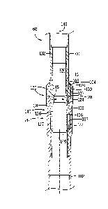
[0026] FIG. 3 is a side view of an embodiment of the first rotating stage
collar 58 described
above with reference to FIG. 2. It should be noted that the second rotating
stage collar 60 may
have a similar configuration with similar components. In the illustrated
embodiment, the first
rotating stage collar 58 includes an upper collar 100 (e.g., annular collar)
and a lower collar 102
(e.g., annular collar). The upper collar 100 is coupled to the second stage 54
of casing 16, while
the lower collar 102 is coupled to the first stage 52 of casing 16. For
example, the upper collar
100 and lower collar 102 may be coupled to the first and second stages 52 and
54, respectively,
via a threaded connection, bolted connection, or other suitable mechanical
connection.
[0027] The upper and lower collars 100 and 102 are coupled to one another
with a load nut
104. In particular, the load nut 104 extends over and radially about the upper
collar 100, and the
load nut 104 threads onto the lower collar 102. As described in further detail
below, the load nut
104 axially captures a load shoulder of the upper collar 100 with the lower
collar 102, which
enables the full weight of the first stage 52 and lower collar 102 to hang off
from the upper collar
(100) while the casing 16 is run into the well.
[0028] The first rotating stage collar 58 also includes shear screws 106
extending radially
inward from an outer surface 108 of the upper collar 100. As described in
detail below, the shear
screws 106 extend through the upper collar 100 and into an inner sleeve of the
rotating stage
collar 58 to hold the inner sleeve in place prior to actuation or the rotating
stage collar 58. As
mentioned above, the rotating stage collar 58 further includes cement ports
110. The cement
ports 110 extend from the outer surface 108 of the upper collar 100 to an
inner circumferential
surface of the upper collar 100. However, as described below, when the first
rotating stage collar
58 is initially run into the wellbore 24, the cement ports 110 are blocked or
occluded by the inner
sleeve of the rotating stage collar 58. After the first rotating stage collar
58 is actuated, the inner
sleeve may be axially displaced downward, and the cement ports 110 may be
opened or exposed
to enable cement 24 flow from within the rotating stage collar 58, through the
cement ports 110,
and into the annulus 62.
[0029] FIG. 4 is a cross-sectional side view, taken within line 4-4 of FIG.
3, of the first
rotating stage collar 58. As described above, the rotating stage collar 58
includes the upper
collar 100 and the lower collar 102, which are coupled to one another via the
load nut 104.
9
CA 2992609 2018-01-23
When the load nut 104 is threaded onto the lower collar 102, an upper shoulder
120 of the load
nut 104 axially captures a load shoulder 122 of the upper collar 100 with an
axial end face 124 of
the lower collar 102. The load shoulder 122 of the upper collar 100 helps
transfer weight from
the first stage 52 of casing 16 to the upper collar 102 and the second stage
54 of casing 16.
However, a majority of the weight of the casing 16 may still be supported by
the wellhead
equipment 14. To further enable support of the second stage 52 casing 16 load,
the first rotating
stage collar 58 includes thrust bearings 126 (e.g., bronze thrust bearings).
Specifically, a first
thrust bearing 128 is disposed between the axial end face 124 of the lower
collar 102 and the
load shoulder 122, and a second thrust bearing 130 is disposed between the
load shoulder 122
and the upper shoulder 120 of the load nut 104. As will be appreciated, the
thrust bearings 126
enable load transfer from the upper collar 100 to the lower collar 102 while
also facilitating and
enabling relative rotation between the upper collar 100 and the lower collar
102.
[0030] As mentioned above, the first rotating stage collar 58 also includes
an inner sleeve 132
disposed within the upper and lower collars 100 and 102. When the rotating
stage collar 58 is
initially coupled to the first and second stages 52 and 54 of casing 16 and
run into the wellbore
24, the inner sleeve 132 is held in place within the upper and lower collars
100 and 102 by the
shear screws 106. For example, the rotating stage collar 58 may include 4, 5,
6, 7, 8, 9, 10, or
more shear screws configured to hold the inner sleeve 132 in place within the
upper and lower
collars 100 and 102. When the inner sleeve 132 is held in place in the
configuration shown in
FIG. 3, the inner sleeve 132 occludes or blocks the cement ports 110 of the
upper collar 100.
Thus, cement 24 flowing through the casing 16 string, and thus through an
inner passage 134 of
the rotating stage collar 58, is blocked from flowing through the cement ports
110. In certain
embodiments, the inner sleeve 132 may be formed from aluminum or other
relatively soft metal
to enable drilling-out of the inner sleeve 132 after the casing cementing
process is completed.
[0031] Furthermore, when the inner sleeve 132 is held in place in the
configuration shown in
FIG. 3, the rotating stage collar 58 is in a locked configuration. That is,
the upper collar 100 and
lower collar 102 are rotationally fixed relative to one another, thereby
blocking relative rotation
of the first and second stages 52 and 54 of casing 16. Relative rotation of
the upper and lower
collars 100 and 102 is blocked via locking protrusions 136 or locking "dogs"
spaced
circumferentially about the inner sleeve 132. In the configuration shown in
FIG. 4, the dogs 136
CA 2992609 2018-01-23
,
of the inner sleeve 132 extend through guide slots 137 of the upper collar 100
and into locking
slots 138 formed in the lower collar 102. In other words, the dogs 136 are
disposed radially
within the locking slots 138 of the lower collar 102 (e.g., relative to a
longitudinal axis 143 of the
rotating stage collar 58), and thus rotation of the inner sleeve 132 and upper
collar 100 (which
are coupled to one another via the shear pins 120) relative to the lower
collar 102 is blocked.
[0032] As shown in FIG. 4, the locking slots 138 are formed in an upper
portion 140 of the
lower collar 102. However, the locking slots 138 are not formed in a lower
portion 142, which is
axially beneath the upper portion 140 (e.g., relative to the longitudinal axis
143 of the rotating
stage collar 58), of the lower collar 102. Instead, the lower portion 142
includes a cavity or
annular groove 144 extending circumferentially about the lower portion 142 of
the lower collar
102. When the dogs 136 are disposed within the cavity 144 of the lower portion
142,
circumferential movement of the dogs 136, the inner sleeve 132, and the upper
collar 100 is
unrestricted. Therefore, to actuate the rotating stage collar 58 from a locked
to unlocked
configuration, the inner sleeve 132 of the rotating stage collar 58 is
displaced axially downward,
as indicated by arrow 146.
[0033] Axially displacement of the inner sleeve 132 is achieved via
launching of a plug down
the casing 16 string and into the first rotating stage collar 58. After the
plug is launched, the plug
will travel down the casing 16 string and will land against a plug seat 148 of
the inner sleeve
132. As described below, the plug enables shearing of the shear screws 106 and
downward axial
displacement of the inner sleeve 132 within the upper and lower collars 100
and 102. In the
illustrated embodiment, the inner sleeve 132 of the first rotating stage
collar 58 has an inner
diameter 150, which may generally or approximately correspond with an outer
diameter of the
plug. More specifically, the outer diameter of the plug may be slightly larger
than the inner
diameter 150 of the seat 148 to enable landing of the plug against the seat
148.
[0034] It will be appreciated that the inner diameter 150 of the inner
sleeve 132 of the first
rotating stage collar 58 may be smaller than an inner diameter of the inner
sleeve of the second
rotating stage collar 60. The diameter of the inner sleeve of the second
rotating stage collar 60
may be larger to enable passage of the plug that is launched to land against
the plug seat 148 of
the first rotating stage collar 58. As a result, actuation of the second
rotating stage collar 60 may
11
CA 2992609 2018-01-23
be achieved with another plug having a larger diameter corresponding to the
larger diameter of
the inner sleeve of the second rotating stage collar 60. Indeed, each
additional rotating stage
collar that is used along the casing 16 string may include an inner sleeve
having a plug seat with
a larger inner diameter than the plug seat inner diameter of the next
successive rotating stage
collar located further downhole along the casing 16 string. Similarly, for
each additional rotating
stage collar used along the casing 16 string, a larger diameter plug will be
used to land against
the respective plug seat of the rotating stage collar to enable actuation of
the rotating stage collar.
[0035] FIG. 5 is a cross-sectional side view of the first rotating stage
collar 58, illustrating a
plug 200 landed against the plug seat 148 of the inner sleeve 132. As
discussed above, the plug
200 is launched down the casing 16 string from the wellhead equipment 14 to
actuate the first
rotating stage collar 58 from the locked configuration shown in FIG. 4 into an
unlocked
configuration. That is, the plug 200 is launched down the casing 16 to the
first rotating stage
collar 58 when relative rotation between the first stage 52 of casing 16 and
the second stage 54 of
casing 16 is desired (e.g., during cementing of the second stage 54 of casing
16 after the first
stage 52 of casing is cemented). It should be noted that the first rotating
stage collar 58 is
actuated from the locked configuration into the unlocked configuration without
lifting the casing
16 string (e.g., with the wellhead equipment 14). As a result, the first stage
52 of casing 16 and
the cement 24 surrounding the first stage 52 of casing 16 may be undisturbed
when the first
rotating stage collar 58 is actuated for rotation of the second stage 54 of
casing 16.
[0036] As mentioned above, the plug 200 is landed against the plug seat 148
of the inner
sleeve 132. In the illustrated embodiment, the plug 200 also includes a
central passage 202. To
launch the plug 200 from the wellhead equipment 14, a ball 204 may be used to
block the central
passage 202, build up pressure behind and above the plug 200, and launch the
plug 200 to the
first rotating stage collar 58. However, in other embodiments, the plug 200
may not include
the central passage 202, and thus the ball 204 may not be used. In certain
embodiments, the plug
200 may be a rubber or other elastomeric material that may deform to create a
seal with the inner
sleeve 132 to block cement 24 from passing the plug 200 within the inner
sleeve 132.
[0037] After the plug 200 and ball 204 are landed within the first rotating
stage collar 58,
cement 24 may be pumped down the casing 16, and pressure of the cement 24 may
build up
12
CA 2992609 2018-01-23
above the plug 200 and the ball 204. Eventually, the pressure will overcome
the yield strength of
the shear pins 106, causing the shear pins 106 to shear and the inner sleeve
132 to be displaced
axially downward, as indicated by arrow 206. As the inner sleeve 132 travels
axially downward,
the dogs 136 of the inner sleeve 132 move along the guide slots 137 of the
upper sleeve 100 and
from the upper portion 140 of the lower collar 102 to the lower portion 142 of
the lower collar
102. As discussed above, when the dogs 136 are disposed in the upper portion
140, rotation of
the inner sleeve 132 and the upper collar 100 coupled to the inner sleeve 132
via the shear pins
106 is blocked via the locking slots 138 formed in the upper portion 140.
However, when the
dogs 136 of the inner sleeve 132 are moved axially downward to the lower
portion 142 of the
inner sleeve 132, the dogs 136 are disposed within the cavity 144 of the lower
portion 142 and
are free to rotate. Thus, the inner sleeve 132 and the upper collar 100 (which
are rotationally
coupled to one another via the dogs 136 extending through the guide slots 137
of the upper collar
100) are free to rotate relative to the lower collar 102. In other words, the
second stage 54 of
casing 16 coupled to the upper collar 100 may be freely rotated with the
wellhead equipment 14
without rotating the lower collar 102 coupled to the first stage 52 of casing
16.
[0038]
It should be noted that the first rotating stage collar 58 shown in FIG. 5 is
not in the
fully unlocked configuration. More specifically, the dogs 136 of the inner
sleeve 132 are not
fully landed against a lower shoulder 208 of the lower portion 142 of the
lower collar 102.
Additionally, in the illustrated embodiment, the cement ports 110 of the upper
collar 100 are still
occluded or blocked by the inner sleeve 132. Indeed, the size (e.g., length)
of the inner sleeve
132 and/or the location of the cement ports 110 along the upper collar 100 is
selected such that
the cement ports 110 are occluded by the inner sleeve 132 until the dogs 136
of the inner sleeve
132 are fully landed against the lower shoulder 208. In this manner, cement 24
pressure above
the plug 200 and the ball 204 may be contained (e.g., and not flow out of the
cement ports 110)
until the rotating stage collar 58 is in the fully unlocked configuration.
Once the dogs 136 are
landed against the lower shoulder 208, the inner sleeve 132 is axially beneath
the cement ports
110 and no longer blocks the cement ports 110, and cement 24 may freely flow
out of the
rotating stage collar 58 through the cement ports 100. For example, FIG. 6 is
a cross-sectional
side view of the first rotating stage collar 58, illustrating the dogs 136 of
the inner sleeve 132
landed against the lower shoulder 208 of the lower collar 102. As indicated by
arrows 220,
13
CA 2992609 2018-01-23
cement 24 may flow through the cement ports 110 into the annulus 62 between
the casing 16
string and the wellbore 24.
[0039] In certain embodiments, the first rotating stage collar 58 may
include other
components. For example, as shown in FIG. 6, the rotating stage collar 58 may
include one or
more seals 240 (e.g., annular seals, elastomeric seals, etc.) disposed between
the upper collar 100
and lower collar 102 and/or between the inner sleeve 132 and the upper collar
100. The seals
240 may block bearing surfaces 242 between the upper collar 100 and lower
collar 102 and/or
between the inner sleeve 132 and the upper collar 100 from becoming
contaminated. In certain
embodiments, the bearing surfaces 242 between the upper collar 100 and lower
collar 102 and/or
between the inner sleeve 132 and the upper collar 100 may be lubricated (e.g.,
with grease or oil)
when the rotating stage collar 58 is assembled to facilitate relative rotation
between the upper
collar 100, lower collar 102, and/or inner sleeve 132 when the rotating stage
collar 58 is in the
unlocked configuration shown in FIG. 6.
[0040] As describe above, the present disclosure relates generally to the
rotating stage collar
58 for coupling two adjacent stages of casing 16 (e.g., first and second
stages 52 and 54) run into
the wellbore 24. Once the casing 16 is run into the wellbore 24, the casing
may be cemented in
place via cement 24 pumped through the casing 16 and into the annulus 62
between the casing
16 and the wellbore 24. The adjacent stages (e.g., first and second stages 52
and 54) of the
casing 16 string may be coupled to one another via the rotating stage collar
58 to selectively
enable relative rotation between adjacent casing string stages. For example,
cement 24 may first
be pumped through the casing 16 string to fill the annulus 62 surrounding the
first stage 52 of
casing 16 while rotating the first and second stages 52 and 54 to improve the
cementing process.
After the first stage 52 of casing 16 is cemented, the rotating stage collar
58 may be actuated or
triggered from the locked configuration into an unlocked configuration. In the
unlocked
configuration, the first and second stages 52 and 54 of the casing 16 string
are rotationally
independent from one another. As a result, the second stage 54 may be rotated
as cement 24 is
pumped into the annulus 62 surrounding the second stage 54 without rotating
the first stage 52 of
casing 16. Indeed, the rotating stage collar 58 may be actuated from the
locked configuration to
the unlocked configuration without lifting the casing 16 string from the
surface. In this manner,
the cement 24 surrounding the first stage 52 may be undisturbed after the
first stage cementing
14
CA 2992609 2018-01-23
process is complete, while enabling rotation of the second stage 54 casing
during completion of
the second stage cementing process.
[0041]
While only certain features of the invention have been illustrated and
described herein,
many modifications and changes will occur to those skilled in the art. It is,
therefore, to be
understood that the appended claims are intended to cover all such
modifications and changes as
fall within the true spirit of the invention.
CA 2992609 2018-01-23