Note: Descriptions are shown in the official language in which they were submitted.
I
ACTIVE LMA OPTICAL FIBER AND LASER SYSTEM USING THE SAME
TECHNICAL FIELD
The technical field generally relates to laser systems providing ultrashort
light
pulses and more particularly concerns the use of an active large mode area
optical
fiber in such systems.
BACKGROUND
Femtosecond lasers are expensive and are sometimes difficult to work with,
given
the complex technology involved and know-how required. Nonlinear pulse
compression is a technique known in the literature for achieving ultrashort
pulses.
The latter proceeds first from a nonlinear interaction, typically self-phase
modulation (SPM), which yields a larger optical bandwidth and resultant
frequency
upchirp along a seed pulse waveform. This may be accomplished, for instance,
through nonlinear pulse amplification along an optical fiber amplifier.
Thereafter,
the amplified pulse can be compressed to shorter durations using a suitable
dispersive optical element. The pulse compression factor then depends on the
extent of the broadened spectrum and the ability of the dispersive element to
compensate for its chirp.
US 8,948,219 (Nodop et al.) and US 9,300,105 (Clowes et al.) teach similar
schemes using optical fibers as the nonlinear amplification medium, where self-
phase modulation takes place. The optical fiber typically includes rare-earth
dopants (such as ytterbium) so as to provide optical amplification, along with
spectral broadening by self-phase modulation. Nodop discloses the use of a
single-mode fiber to achieve efficient spectral broadening. While the small-
core
diameter of single-mode fibers effectively makes operative the spectral
broadening
due to the high peak intensities reached, limitations arise which make it
unlikely in
practice to scale peak powers beyond 10's of kW with this technique. Beyond
these
power levels, the onset of other nonlinear effects (such as stimulated Raman
scattering) becomes detrimental to the laser operation. While Clowes mentions
the
CA 2993070 2018-01-26
2
benefits of active optical fibers with larger core diameters, he is silent as
to which
favorable conditions would be conducive to achieving ultrashort-pulse
durations
after compression. Clowes instead aims to improve pulse compression by
splitting
the pulses in two distinct portions (base and surge pulse portions) and
further
provides details about external means for governing each portion in accordance
with heuristic criteria.
There remains a need for active optical fibers with large core diameters
configuration providing favorable conditions for nonlinear pulse amplification
and
lo .. subsequent pulse compression.
SUMMARY
In accordance with an aspect of the present description, there is provided a
laser
system.
The laser system includes a light pulse generator generating light pulses.
The laser system further incudes a nonlinear amplification module comprising
an
active Large Mode Area (LMA) optical fiber having an input end and an output
end.
The LMA optical fiber has a core having a core diameter of at least 35 pm and
a
cladding structure having a cladding diameter. The LMA optical fiber is
configured
to promote the onset of nonlinear spectral broadening of the light pulses
through
Self-Phase Modulation at the output end. The LMA optical fiber includes,
successively, a first and a tapered second section. The first section receives
and
supports propagation of the light pulses in multiple transversal modes, which
include a fundamental mode and a number of high order modes. The core and
cladding diameters are constant along the first section. The first section is
further
configured to suppress the high order modes propagating therealong. The
tapered
second section receives the fundamental mode from the first section. The core
and
cladding diameters increase gradually along the second section so as to
provide
an adiabatic transition of the fundamental mode along the tapered second
section.
Date Recue/Date Received 2022-07-25
3
The laser system also includes a pulse compressor downstream the nonlinear
amplification module and including a dispersive optical element configured to
compress the light pulses.
In some implementations, the light pulses generated by the light pulse
generator
have a duration within a range between about 10 and 100 picoseconds,
preferably
between about 20 and 50 picoseconds, and further preferably between about 30
and 35 picoseconds. The radiation wavelength of the light pulses may be within
a
range between about 1020 and 1080 nm. The light pulses generated by the light
.. pulse generator may be substantially Fourier-transform limited.
In some implementations, the light pulse generator may include one of a pulsed
laser diode, a mode-locked fiber laser and a diode-pumped solid-state laser.
In some implementations, the LMA optical fiber may further include a third
section
extending from a larger end of the tapered second section. The core and
cladding
diameters are constant along this third section and correspond to the core and
cladding diameters at the larger end of the tapered second section.
In some implementations, the core of the LMA optical fiber is doped with an
active
ion dopant along one or more of the first, second and third sections thereof.
The
active ion dopant is preferably a rare-earth element.
In some implementations, the LMA optical fiber is counter-pumped.
In some implementations, the LMA optical fiber has a transversal refractive
index
profile including a depression in the cladding structure immediately adjacent
the
core, and the first section of the LMA optical fiber is coiled according to a
bend
radius providing the suppressing of the high order modes through bending
losses.
For example, the core has a refractive index ni and the cladding structure
includes,
concentrically from the core outwards:
¨ a depressed-index cladding layer having a refractive index n2;
CA 2993070 2018-01-26
4
- an inner cladding having a refractive index n3; and
- an outer cladding having a refractive index n4;
wherein n4<n2<n3<ni.
In some implementations, the LMA optical fiber is polarization-maintaining,
and for
example includes stress-applying rods extending longitudinally within the
cladding
structure in parallel to the core.
In some implementations, the nonlinear amplification module further includes
at
least one pre-amplifying stage upstream the LMA optical fiber.
In some implementations, the dispersive optical element of the pulse
compressor
is a volume Bragg grating.
In accordance with another aspect, there is provided a laser system including
a
laser oscillator generating seed light pulses, and a Large Mode Area (LMA)
optical
fiber configured to amplify the seed light pulses and to induce a nonlinear
spectral
broadening of said seed light pulses through Self-Phase Modulation, thereby
obtaining amplified spectrally broadened light pulses.
The LMA optical fiber includes:
o a rare-earth doped core and a cladding structure surrounding the core;
O a transversal refractive index profile comprising a depression in the
cladding structure immediately adjacent the core;
o a core diameter and a numerical aperture providing multimode
guidance of the seed light pulses in a fundamental mode and a number
of high order modes, said core diameter being at least 35 pm; and
O a longitudinal spatial profile defining an input section having a
constant
input effective mode area, an output section having a constant output
effective mode area, and a tapered section therebetween providing an
adiabatic transition between the input and output effective mode
areas, the input section being coiled according to a bent radius
Date Recue/Date Received 2022-07-25
5
providing a suppression of the high order modes through bending
losses while preserving propagation of the fundamental mode.
The laser system further includes a pulse compressor comprising a dispersive
optical element configured to compress the amplified spectrally broadened
light
pulses.
In some implementations, the seed light pulses have a duration within a range
between about 10 and 100 picoseconds, preferably between about 20 and 50
picoseconds, and further preferably between about 30 and 35 picoseconds. The
radiation wavelength of the seed light pulses may be within a range between
about
1020 and 1080 nm. The seed light pulses may be substantially Fourier-transform
limited.
In some implementations, the light pulse generator includes one of a pulsed
laser
diode, a mode-locked fiber laser and a diode-pumped solid-state laser.
In some implementations, the LMA optical fiber is counter-pumped.
In some implementations, the core has a refractive index ni and the cladding
structure comprises, concentrically from the core outwards:
¨ a depressed-index cladding layer having a refractive index n2;
¨ an inner cladding having a refractive index n3; and
¨ an outer cladding having a refractive index n4;
wherein n4<n2<n3<ni.
In some implementations, the LMA optical fiber is polarization-maintaining,
and
may include stress-applying rods extending longitudinally within the cladding
structure in parallel to the core.
In some implementations, the laser system further includes at least one pre-
amplifying stage upstream the LMA optical fiber.
CA 2993070 2018-01-26
6
In some implementations, the dispersive optical element of the pulse
compressor
is a volume Bragg grating.
In accordance with yet another aspect, there is provided a Large Mode Area
(LMA)
optical fiber for amplifying light pulses, including:
- a rare-earth doped core and a cladding structure surrounding said core;
- a transversal refractive index profile comprising a depression in the
cladding
structure immediately adjacent the core;
- a core diameter and a numerical aperture providing multimode guidance of
the light pulses in a fundamental mode and a number of high order modes,
said core diameter being at least 35 pm; and
- a longitudinal spatial profile defining an input section having a
constant input
effective mode area, an output section having a constant output effective
mode area, and a tapered section therebetween providing an adiabatic
transition between the input and output effective mode areas, the input
section being coiled according to a bent radius providing a suppression of
the high order modes through bending losses while preserving propagation
of the fundamental mode.
In some implementations, the LMA optical fiber may be configured to amplify
the
light pulses and to induce a nonlinear spectral broadening of the seed light
pulses
through Self-Phase Modulation.
In some implementations, the LMA optical fiber is counter-pumped.
In some implementations, the core has a refractive index Iii and the cladding
structure comprises, concentrically from the core outwards:
- a depressed-index cladding layer having a refractive index n2;
- an inner cladding having a refractive index n3; and
¨ an outer cladding having a refractive index n4;
wherein n4<n2<n3<ni.
Date Recue/Date Received 2022-07-25
7
In some implementations, the LMA optical fiber further includes stress-
applying
rods extending longitudinally within the cladding structure in parallel to the
core.
Advantageously, in some implementations the laser system and LMA optical fiber
as described herein provide improvements in the performance of nonlinear pulse
compression. Embodiments can provide both excellent beam quality and high
peak powers after nonlinear amplification and pulse compression. In examples
of
implementation an effective mode area superior to 1000 pm2 in the larger
region
of the second section of the LMA optical fiber and/or in the third section may
be
obtained, which allows for the scaling of the output peak power while at the
same
time preserving a diffraction-limited output (for example M2 < 1.2).
Other features and advantages will be better understood upon reading of
is embodiments thereof with reference to the appended drawings.
BRIEF DESCRIPTION OF THE DRAWINGS
FIG. 1 is a block diagram illustrating a scheme for nonlinear pulse
compression.
FIG. 2 is a schematic representation of a laser system using a LMA optical
fiber
according to an embodiment; FIG. 2A is a diagram showing a longitudinal cross-
section of the LMA optical fiber.
FIG. 3 is a graph of the core/cladding diameters and effective mode area along
a
LMA optical fiber in one example of implementation.
FIGs. 4A and 4B respectively show the cross-section and the refractive index
profile of a LMA optical fiber provided with a depressed-index cladding layer
in
accordance with an embodiment.
CA 2993070 2018-01-26
8
FIG. 5 is a graph of the bend-induced propagation losses of linearly-polarized
LPoi
and LIpli modes in 35/250 pm section of a test LMA optical fiber as a function
of
the bending radius.
FIG. 6 is a graph of the SPM-broadened optical spectra through nonlinear
amplification of short pulses for different peak powers in the test LMA
optical fiber.
FIG. 7 is a graph of the B-integral as a function of peak power following
nonlinear
pulse amplification in the test LMA optical fiber (as retrieved from RMS width
of
SPM-broadened optical spectra).
FIG. 8 is a graph of the signal (forward) and pump (backward) power along the
test
LMA optical fiber (shown schematically by the dashed line) according to one
embodiment.
FIG. 9 is a graph of the B-integral along the test LMA optical fiber (shown
schematically by the dashed line) according to one embodiment.
FIG. 10 is a graph of the intensity autocorrelations of optical pulses after
amplification in the test LMA optical fiber (dashed line) and subsequent
compression using a chirped VBG (straight line), with a compression factor
close
to 25x.
DETAILED DESCRIPTION
The present description concerns a laser system based on nonlinear pulse
compression and a LMA optical fiber for use in such a system.
Laser systems such as described herein may find widespread use in industrial,
scientific and medical applications, for instance when intense and energetic
ultrashort pulses of light are needed to probe matter or modify material
properties
CA 2993070 2018-01-26
9
within a microscopic volume or during a very short lapse of time (e.g. through
multiphoton processes).
Referring to FIG. 1, in some implementations, the laser system 20 includes a
light
pulse generator 22 for generating light pulses 24, a nonlinear amplification
module
26 amplifying and spectrally broadening the light pulses 24 into spectrally
broadened light pulses 54, and a dispersive pulse compressor 28 for
compressing
the spectrally broadened light pulses 54.
Referring to FIG. 2, as mentioned above, an example of a configuration of the
laser
system 20 is schematically illustrated.
In accordance with some implementations, the light pulse generator 22, also
called
laser oscillator, can be embodied by a device or combination of devices
emitting
short optical or light pulses 24, which may be referred to as seed light
pulses. The
light pulses 24 may be generated from a laser diode using external phase
modulation and subsequent spectral filtering (see for example Deladurantaye et
al. in US 8,798,107). The seed light pulses 24 could also originate from a
gain-
switched laser diode, as well as from a mode-locked fiber laser or diode-
pumped
solid-state laser. The duration of the seed light pulses 24 as emitted from
the laser
oscillator could typically be selected within a range between about 10 and 100
ps,
and preferably in the range between about 20 and 50 ps. In some embodiments,
the seed light pulses 24 may have a duration within a range between about 30
and
35 ps and a radiation wavelength within a range between about 1020 and 1080
nm. It is to be noted that the term "about" as used herein is undertood to
mean
approximately in the region of, and around. When the term "about" is used in
relation to a numerical value, it modifies it, for example, above and below by
a
variation of 10% in relation to the nominal value. This term may also take
into
account, for example, the experimental error of a measuring apparatus or
rounding. The seed light pulses 24 as generated from the light pulse generator
are
preferably substantially unchirped, i.e. substantially Fourier transform-
limited,
CA 2993070 2018-01-26
10
although small amounts of frequency chirp may be tolerable. In the illustrated
configuration, the light pulse is for example embodied by a 1064 nm pulsed
laser
diode.
The nonlinear amplification module 26 is provided downstream the light pulse
generator 22. The nonlinear amplification module 26 may include one of more
pre-
amplifying stages 27, for example rare-earth doped fiber amplifiers providing
a first
amplification of the seed light pulses 24. The rare-earth doped fiber
amplifiers may
be forward or backward pumped by a pump source 29a, for example a 976 nm
laser diode.
The nonlinear amplification module 26 then includes an active Large Mode Area
(LMA) optical fiber 30. Preferably, the active LMA optical fiber 30 is the
last
amplification stage of the amplification module 26, if multiple amplification
stages
are provided.
As known to one skilled in the art, the expression "active fiber" typically
refers to
an optical fiber which provides amplification of the guided light. Active
fibers are
typically core-doped with a rare-earth element and pumped with a pump beam
from a pump source 29b. The active ion dopant may be a rare-earth element,
such
as for example erbium (Er), ytterbium (Yb), thulium (Tm), etc. In the
illustrated
configuration of FIG. 2, the pump source is for example a 976 nm laser diode
injected in the LMA optical fiber 30 in a counter-propagating direction to the
light
pulses 24. Of course, other pumping schemes may be envisioned as well known
in the art.
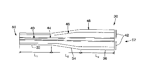
Still referring to FIG. 2 and with additional reference to FIG. 2A, the LMA
optical
fiber 30 includes a core 40 having a core diameter and a cladding structure 42
having a cladding diameter. It will be readily understood that the cladding
structure
42 may include a plurality of cladding layers, and that the cladding diameter
may
be embodied by the width of one of those cladding layers, typically the
cladding
CA 2993070 2018-01-26
11
layer providing light guidance to the pump beam (inner cladding 46 in the
embodiments illustrated herein and explained further below).
The LMA optical fiber has an input end 50 on the side of the light pulse
generator
22, and an output end 52 on the side of the pulse compressor 28. In-between,
in
the illustrated embodiment, the LMA optical fiber 30 successively includes a
first
or input section 32, a tapered second section 34 and a third or output section
36.
The core and cladding diameters are constant along each of the first and third
sections 32 and 36, and define respectively a constant input effective mode
area,
and a constant output effective mode area. The output effective mode area is
larger
than the input effective mode area. The expression "effective mode area is
understood in the contaxt of the present description to refer to a
quantitative
measure of the area, along the transverse plane of the LMA optical fiber,
which is
effectively occupied by the fundamental mode. Furthermore, the expression
"tapered" used herein refers to the variation in diameter of the LMA optical
fiber
along the second section 34. The core and cladding diameters increase
gradually
along the tapered second section 34, providing an adiabatic transition between
the
input and output effective mode areas. One skilled in the art will readily
understand
that the expression "adiabatic" refers to a slow variation of the field
amplitude of
the fundamental mode so that coupling to high order modes is substantially
avoided. In some variants, the third section 36 may be omitted without
departing
from the scope of the invention, in which case the output end 52 is defined by
the
larger extremity of the tapered second section 34. The first, second and third
sections 32, 34, 36 may have different lengths, respectively labelled Li, L2
and L3
on FIG. 2A.
The first section 32 receives and supports the propagation of the seed light
pulses
24 in multiple transversal modes, which include a fundamental mode and a
number
of high order modes (HOMs). The diameter of the core 40 is preferably large
enough for the fundamental mode to benefit from a substantially large input
effective mode area compared to a typical single-mode fiber, whereas the
CA 2993070 2018-01-26
12
numerical aperture NA (with NA2 = ni2¨ n22, where ni is the refractive index
of the
core and n2 is the refractive index of the innermost cladding layer) should be
low
enough to minimize the number of supported HOMs. An optical fiber meeting such
conditions is what is generally understood as a LMA optical fiber by persons
skilled
6 in the art. It is however to be understood that the core numerical
aperture may not
be set to arbitrarily small values as this may lead to excessive losses from
fiber
bending and/or small fabrication imperfections. Numerical apertures of LMA
optical
fibers have typical values between about 0.05 and 0.07, although it can be
made
somewhat smaller or larger.
The first section 32 of the LMA optical fiber 20 is configured to suppress the
high
order modes propagating therealong, so that the tapered second section 34
receives from the first section 32 only the light pulses carried by the
fundamental
mode. In one embodiment, HOMs suppression is achieved through bend-induced
losses enhanced by the provision of a reduced-index cladding layer immediately
surround the core.
Referring to both FIGs. 2A and 4A, there is shown an example of a cladding
structure 42 of a LMA optical fiber 30 according to one embodiment. In such an
embodiment, the core has a refractive index ni and diameter di and the
cladding
structure 42 includes a thin depressed-index cladding layer 44 immediately
surrounding the core 40, having a diameter dz and a refractive index nz, the
latter
being lower than the refractive index of the core (nz < ni) such as to enable
total
internal reflection guidance within the core 40. The depressed-index cladding
layer
44 is surrounded by an inner cladding 46 having a diameter d3 and refractive
index
n3, the latter being larger than the refractive index of the depressed-index
cladding
layer 44 (n3> nz) but lower than the refractive index of the core 40 (n3 <
ni). The
inner cladding 46 is surrounded by an outer cladding 48 having a diameter da.
The
outer cladding 48 usually consists of a fluorine-doped silica glass layer, of
a dual-
layer fluoroacrylate polymer coating or of a combination of both, the latter
having
a low enough refractive index na so as to yield high numerical aperture
(typically
CA 2993070 2018-01-26
13
0.22 for fluorine-doped glass or 0.46 for fluoroacrylate polymers) for guiding
the
pump beam launched in the inner cladding 46 to invert the rare-earth ions
dopants
in the core 40. Optionally, the LMA optical fiber 30 may additionally include
stress-
applying rods 49 so as to induce stress birefringence and thereafter preserve
or
maintain the linear polarizations of lightwaves along the optical fiber, as
known in
the art as a polarization-maintaining optical fiber. The transversal
refractive index
profile of such a LMA optical fiber 30 is shown in FIG. 4B, where it can be
seen
that n4<n2<n3<ni.
A feature of such a configuration is the index depression in the cladding
structure
44 immediately adjacent the core 40, which is instrumental in suppression of
HOMs
along the first section 32. As one skilled in the art would readily
understand, HOMs
suppression through bend-induced loss may be enhanced by coiling or bending
the first section 32 of the LMA optical fiber 30, as the evanescent fields of
HOMs
then extend further beyond the depressed-index cladding layer 44, thus
lowering
the effective numerical aperture of HOMs because of the greater overlap with
the
inner cladding 46. In such implementations, the first section 32 of the LMA
optical
fiber 30 is therefore coiled according to a bend radius providing this
suppression
of the high order modes through bending losses. As one skilled in the art will
readily
understand, the thickness and depth of the depressed-index cladding layer may
be engineered for optimal discrimination between linearly-polarized LPoi and
LP,ii
modes in the first section of the optical fiber, and as such, are intimately
tied to the
core diameter and core NA. Preferably, the index depression relative to the
refractive index of the inner cladding 46 and the bend radius may be designed
so
as to achieve differential propagation losses between linearly-polarized LPoi
and
LEvi modes exceeding 10 dB/m in the first section 32 of the LMA optical fiber.
Referring to FIG. 5, there is shown the bend-induced propagation losses of
linearly-
polarized LPoi and LPti modes in the first section of a LMA optical fiber
having a
core to cladding diameter ratio of 35/250 pm as a function of the bending
radius. It
can be seen that in this example, differential bending loss between modes
larger
CA 2993070 2018-01-26
14
than 10 dB/m are readily achieved with coiling diameters smaller than about 16
cm.
It is to be noted that the enhanced bend-induced losses attributed to the
depressed-index cladding layer are not based on a resonant coupling of HOMs to
the cladding structure. Instead, suppression of HOMs becomes simply more
efficient once the fiber is coiled, as the evanescent field of HOMs extends
further
beyond the depressed-index cladding layer, thus lowering the effective
numerical
aperture seen by HOMs because of a greater overlap with the inner cladding.
More
information on such a depressed-index cladding layer may be found in U.S.
patent
number 8,731,358 (Pare et al).
It will further be understood by one skilled in the art that other HOMs
suppressing
configurations may be considered, such as for example configurations based on
HOMs delocalization or confined doping, both of which results in enhanced
modal
discrimination because of the poor overlap of HOMs with the doped core region.
Referring back to FIGs 2 and 2A, the adiabatic transition of the mode field in
the
tapered second section 34 of the LMA optical fiber 30 preferably preserves
single-
mode propagation towards the larger end of the LMA optical fiber 30. The core
and
cladding diameters of the LMA fiber increase gradually along the tapered
second
section 34 so as to provide an adiabatic transition of the fundamental mode.
In
operation, therefore, the seed light pulses 24 are launched into the LMA
optical
fiber 30 at the input end 50, in the first section 32 where HOMs are
suppressed
and the fundamental mode is guided by total internal reflection along the core
40.
Adiabatic transition of the mode field in the tapered second section 34
thereafter
substantially preserves single-mode amplification towards the larger end of
the
LMA optical fiber, whereby the light pulses that comes out at the output end
52
benefit from an increased mode area.
CA 2993070 2018-01-26
15
The core 40 of the LMA optical fiber 30 is preferably doped with the one or
more
active ion dopant along one or more of the first, second or third sections 32,
34
and 36 of the LMA optical fiber 30. In typical implementations, the LMA
optical fiber
is manufactured from a single drawing process and all sections thereof
therefore
have the same composition. As known to those skilled in the art, doping
provides
amplification of the travelling light pulses 24 as they propagate among the
LMA
optical fiber.
The LMA optical fiber 30 may be configured to promote the onset of nonlinear
113 spectral broadening of the light pulses 24 through Self-Phase
Modulation (SPM)
at its output end 52. In some implementations, the energy levels reached in
the
LMA optical fiber are sufficient for SPM-induced spectral broadening to occur
as a
result of nonlinear pulse propagation along the LMA optical fiber. By way of
example, the results summarized in the table below were obtained in one
experimental implementation of the present laser system, using the
configuration
illustrated in FIG. 2:
Laser oscillator LMA optical fiber Compressor
Pulsewidth - 35 Ps - 35 Ps - 1-2 ps
Pulse energy < 10 nJ - 50 pJ - 20-40 pJ
Peak power <1 kW - 1-2 MW - 10-20 MW
It is to be noted that in this experiment, the core/cladding diameter ratio
was 35/250
pm in the first section 32 and 56/400 pm in the third section 36. The
variation of
the effective mode area along the LMA optical fiber is shown in FIG. 3.
As illustrated in FIG. 6, broadening factors as large as 50x the initial
bandwidth
were measured. A peak nonlinear phase shift (or B-integral, as known by
persons
skilled in the art) close to 15-rr radians were obtained, as shown in FIG. 7.
In this
implementation the LMA optical fiber was counter-pumped and operated at a very
high gain (between about 30-50 dB), such that most of the accumulated
nonlinear
phase takes place substantially at the end of the third section of the LMA
optical
CA 2993070 2018-01-26
16
fiber, where the effective mode area is the largest (see FIGs. 8 and 9). In
this
manner, much higher peak powers (> 1 MW) may be achieved than with
conventional LMA fibers differing from the LMA optical optical fiber described
herein. Indeed, deleterious nonlinear effects such as stimulated Raman
scattering,
that would otherwise impair the amplifier efficiency, can be avoided. Counter-
pumping of the LMA optical fiber can be advantageous to optimize the amplifier
gain at the end of the third section. It is to be noted that the SPM-broadened
spectra reported herein shows no hint of simultaneous XPM process with
presumed HOMs, which constitutes strong evidence for single-mode propagation
along the LMA optical fiber and bodes well for subsequent pulse compression.
Referring back to FIG. 2, the laser system 20 further includes a pulse
compressor
28 downstream the nonlinear amplification module 26. The pulse compressor 28
includes a dispersive optical element 38 configured to compress the spectrally
broadened light pulses 54. The dispersive optical element 38 may for example
be
embodied by a diffraction grating pair, or a chirped volume Bragg grating
(VBG).
VBGs may be of special interest in some implementations as they are simple to
use and require less space than grating pairs. In the experiment reported
above,
pulse compression factors as high as 25x have been demonstrated, yielding
pulse
durations (FWHM) after compression close to 1.5 ps (see FIG. 10). Such a
compression factor is estimated to yield a tenfold increase in peak power (¨
10-20
MW) after pulse compression, thus rivaling with laser systems based on chirped-
pulse amplification (CPA). The intensity autocorrelation trace of FIG. 10
shows a
fraction of the energy is shed in the pulse pedestal upon compression. Indeed,
the
chirped VBG only compensates for the linear part of the frequency upchirp,
which
corresponds roughly to the central portion of the spectrally broadened light
pulses
54, whereas SPM-induced time-dependent phase-shift yields nonlinear chirp at
the
pulse leading/trailing edges (the latter is well known to persons skilled in
the art).
The dispersive rate of the chirped VBG used to perform compression in this
case
is ¨ 8.4 ps/nm. It is nonetheless possible to contemplate other embodiments
where
dispersive rates between about 0.5-50 ps/nm would be appropriate, depending on
CA 2993070 2018-01-26
17
the duration of the seed optical pulses and the extent of the induced spectral
broadening. As a guideline, the following formula is provided to convey a
sense of
the dispersion D (in ps/nm) needed to achieve near optimal pulse compression:
D= ____ ... A
= ________________________________________ = r"'"
41n2 A2 (pmAx
where c is the speed of light in vacuum, A is the laser wavelength, TFWHM the
duration of the seed light pulses (at FWHM) generated by the oscillator
(assuming
temporal pulse broadening due to dispersion in the successive fiber amplifier
stages is negligible) and pMAX is the SPM-induced peak nonlinear phase
accumulated along the LMA optical fiber.
It is to be noted that as pulse compression yields durations below a few
picoseconds, modal dispersion may come into play and likely spoil pulse
compression unless single-mode guidance is effectively enforced. Modal
dispersion in multimode fibers generally results in a walk-off between
different
propagation modes. Given that LMA fibers are inherently multimode (or few-
moded
as sometimes referred to), without HOMs suppression, the output of the LMA
fiber
would be expected to spread over multiple time-delayed sub-pulses. For
instance,
differential group delay between linearly-polarized LPoi and LPii modes along
a
LMA optical fiber having similar attributes as the one considered herein
ranges
roughly between 0.3-0.5 ps/m. Considering that the amplifier fiber length may
vary
in practice between roughly 2 to 6 m (depending upon the pump/signal
wavelengths and fiber parameters), group delays (or walk-off) of the same
order
or even greater than actual pulse durations as demonstrated after compression
would be expected at the amplifier output. Sub-optimal pulse compression may
therefore result from modal dispersion, with pulse durations longer and/or
pedestals larger than expected, and ultimately lower peak powers.
It will be readily understood that the laser system described herein may
include
additional optical, electrical or mechanical components as will know in the
art. By
CA 2993070 2018-01-26
18
way of example, the system of FIG. 2 includes optical components such as
dichroic
beam splitters DBS, an optical isolator ISO, residual pump dumps RPDs and
lenses L. Any other components directing, separating, shaping focusing,
filtering,
or otherwise acting on a light beam can also be provided.
Of course, numerous modifications could be made to the embodiments described
above without departing from the scope of the present invention.
,
CA 2993070 2018-01-26