Note: Descriptions are shown in the official language in which they were submitted.
84106100
PROCESSING BIOMASS BY IRRADIATION
This application is a division of Canadian Application Serial No. 2,902,350
which is a
division of Canadian Patent Serial No. 2,722,601, filed April 28, 2009.
TECHNICAL FIELD
This invention relates to processing biomass, such as methods and systems for
processing biomass.
BACKGROUND
Various carbohydrates, such as cellulosic and lignocellulosic materials, e.g.,
in fibrous
form, are produced, processed, and used in large quantities in a number of
applications. Often
such materials are used once, and then discarded as waste, or are simply
considered to be
waste materials, e.g., sewage, bagasse, sawdust, and stover.
SUMMARY
Biomass can be processed to alter its structure at one or more levels. The
processed
biomass can then be used, for example as a source of materials and/or fuel.
In general, the invention pertains to methods of changing a molecular and/or a
supramolecular structure of a biomass feedstock. As will be discussed below,
in some
implementations, the methods include irradiating and quenching the biomass
feedstock. In
other implementations, the methods include irradiating the feedstock, cooling
the feedstock,
and again irradiating the feedstock.
The invention as claimed relates to a biomass feedstock processing system
comprising:
one or more irradiating devices configured to irradiate a biomass feedstock
with at least two
separate doses of radiation; and a cooling device configured to cool the
biomass feedstock
between doses of radiation.
1
CA 2993072 2019-06-12
84106100
Carbohydrate-containing materials (e.g., biomass materials or biomass-derived
materials, such as starchy materials, cellulosic materials, lignocellulosic
materials, or
biomass materials that are or that include significant amounts of low
molecular weight
sugars (e.g., monosaccharides, disaccharides, or trisaccharides), can be
processed to
change their structure, and products can be made from the structurally changed
materials.
For example, many of the methods described herein can provide cellulosic
and/or
lignocellulosic materials that have a lower molecular weight and/or
crystallinity relative to
a native material. Many of the methods provide materials that can be more
readily utilized
by a variety of microorganisms to produce useful products, such as hydrogen,
alcohols
(e.g., ethanol or butanol), organic acids (e.g., acetic acid), hydrocarbons,
co-products
(e.g., proteins) or mixtures of any of these. Many of the products obtained,
such
la
CA 2993072 2019-06-12
WO 2009/140057
PCT/US20.41942
as ethanol or n-butanol, can be utilized as a fuel for powering cars, trucks,
tractors, ships
or trains, e.g., as an internal combustion fuel or as a fuel cell feedstock.
Many of the
products obtained can also be utilized to power aircraft, such as planes,
e.g., having jet
engines or helicopters. In addition, the products described herein can be
utilized for
electrical power generation, e.g., in a conventional steam generating plant or
in a fuel cell
plant.
= In one aspect, the invention features methods that include quenching a
biomass
feedstock that has been irradiated to ionize the biomass feedstock so that the
feedstock
has a first level of radicals which are detectable with an electron spin
resonance
to spectrometer, to an extent that the radicals are at a second level lower
than the first level.
In another aspect, the invention features methods that include irradiating a
biomass feedstock to ionize the biomass feedstock so that the feedstock has a
first level
of radicals which are detectable with an electron spin resonance spectrometer,
and
quenching the irradiated biomass feedstock to an extent that the radicals are
at a second
level, lower than the first level, in the quenched biomass feedstock.
Some methods further include processing the irradiated and quenched biomass
feedstock to produce a product.
Some implementations include one or more of the following features.
Quenching can include quenching the radicals to a level that is no longer
detectable with the electron spin resonance spectrometer, e.g., less than
about 1014 spins.
Quenching can include applying pressure to the biomass, e.g., a pressure of
greater than.
about 1000 psi. Pressure can be applied together with the application of heat.
Quenching
can include contacting the biomass with a gas capable of reacting with the
radicals, e.g.,
contacting the biomass with a fluid capable of penetrating into the biomass
and reacting
with the radicals. Quenching can also, or alternatively, include contacting
the biomass
with an antioxidant. In some cases, the biomass feedstock includes an
antioxidant
dispersed therein, and quenching includes contacting the antioxidant dispersed
in the
biomass feedstock with the radicals.
In another aspect, the invention features a method including irradiating a
biomass
feedstock that has been prepared by reducing one or more dimensions of
individual
pieces of the biomass feedstock, using an apparatus comprising an accelerator
configured
2
CA 2993072 2018-01-26
=
WO 2009/140057
PCT/US2009/041942
to accelerate particles, such as electrons or ions, wherein the apparatus is
capable of
processing greater than 1,000 tons of biomass material per year, e.g., greater
than 10,000,
25,000, 50,000, 100,000, or even greater than 1,000,000 tons of biomass per
year.
In a further aspect, the invention features irradiating a biomass feedstock,
e.g.,
with ionizing radiation of electrons or ions, to change a molecular and/or
supramolecular
structure of the biomass feedstock, cooling the biomass feedstock, and then re-
irradiating
the biomass feedstock. The two applications of radiation can be the same or
different,
e.g., the same kind, such as electrons at the same level
The invention also features products formed by these methods, and systems for
performing the methods.
Some implementations of these methods include one or more of the following
features.
The biomass feedstock can be cooled to an extent that after cooling the
biomass is
at a temperature below its initial temperature prior to irradiation. Cooling
of the biomass
can include contacting the biomass with a fluid at a temperature below the
initial
temperature of the biomass or below the temperature of the biomass after
irradiation.
Each irradiation of the biomass feedstock can be performed as the biomass
feedstock is being pneumatically conveyed in a fluid. Radiation can be applied
as the
biomass feedstock falls under the influence of gravity. For example, the
biomass can be
conveyed from a first belt at a first height and captured by a second belt at
a second level,
lower than the first level, the trailing edge of the first belt and the
leading edge of the
second belt defining a gap, and ionizing radiation can be applied to the
biomass feedstock
in the defined gap. During irradiation the biomass can be conveyed past a
particle gun
and through a beam of charged particles. The biomass feedstock may have a bulk
density
of less than about 0.25 g/cm3 in a region under and/or above the beam.
In another aspect, the invention features methods of changing a molecular
structure and/or a supramolecular structure of a starchy material or of a low
molecular
weight sugar, such as sucrose, in a biomass feedstock comprising at least
about 10
percent by weight of the low molecular weight sugar. The methods include
processing a
treated biomass feedstock to produce a product, the treated biomass feedstock
having
been prepared by pretreating a biomass feedstock using a pretreatment method
that
3
CA 2993072 2018-01-26
=
WO 2009/140057 PCTMS2009/041942
changes the molecular structure and/or supramolecular structure of the starchy
material or
of the low molecular weight sugar portion, selected from radiation,
sonication, pyrolysis,
and oxidation.
= In another aspect, the invention features methods of treating a biomass
feedstock
including a starchy material to change the molecular structure and/or
supramolecuiar
structure of the starchy material, with at least one method selected from the
group
consisting of radiation, sonication, pyrolysis, and oxidation.
Any of the above aspects of the invention can, in some implementations,
include
one or more of the following features.
The method can further include treating the biomass feedstock with one or more
other pretreatment methods, wherein the other pretreatment methods are
selected from
sonication, pyrolysis, and oxidation.
Radiation can be in the form of an electron beam, which can be applied, for
example, at a total dosage of between about 101V1Rad and about 50 MRad. The
radiation
can be ionizing radiation_
Processing can include making a combustible fuel. In some cases, processing
includes converting the irradiated material utilizing a microorganism having
the ability to
convert at least about 1 percent by weight of the biomass to the fuel.
In some implementations, processing comprises fermenting the feedstock,
aerobically or anaerobically, to produce a product such as a fuel, e.g.,
ethanol. For
example, processing may comprise contacting the feedstock with a microorganism
having the ability to convert at least a portion, e.g, at least about I
percent by weight, of
the feedstock to the product. The microorganism can be a natural microorganism
or an
engineered microorganism. For example, the microorganism can be a bacterium,
e.g., a
cellulolytic bacterium, a fungus, e.g., a yeast, a plant or a protist, e.g.,
an algae, a
protozoa or a fungus-like protist, e.g., a slime mold. When the organisms are
compatible,
mixtures may be utilized.
The product can include one or more of hydrogen, organic acids, proteins,
hydrocarbons, and alcohols, e.g., ethanol, n-propanol, isopropanol, n-butanol,
and
mixtures thereof. Other examples of products that may be produced by the
methods
disclosed herein include mono- and polyfunctional C1-C6 alkyl alcohols, mono-
and
4
CA 2993072 2018-01-26
S
WO 2009/140057
PCT/US2009/041942
poly-flinctional carboxylic acids, Cl-C6 hydrocarbons, and combinations
thereof. Other
examples of alcohols include methanol, ethylene glycol, propylene glycol, 1,4-
butane
dial, glycerin, and combinations thereof. Carboxylic acids include formic
acid, acetic
acid, propionic acid, butyric acid, valeric acid, caproic acid, palmitic acid,
stearic acid,
oxalic acid, malonic acid, suceinic acid, glutaric acid, oleic acid, linoleic
acid, glycolic
acid, lactic acid, y-hydroxybutyrie acid, and combinations thereof.
Hydrocarbons include
methane, ethane, propane, pentane, n-hexane, and combinations thereof. Many of
these
products may be used as fuels.
The method can further include preparing the biomass feedstock by reducing one
to or more dimensions of individual pieces of the biomass feedstock.
In some cases, the biomass feedstock has internal fibers, and the biomass
feedstock has been sheared to an extent that its internal fibers are
substantially exposed.
The biomass feedstock can in some cases include or be made up of discrete
fibers ancUor
particles having a maximum dimension of not more than about 0.5 mm.
The biomass feedstock can be prepared and then pretreated, or pretreated and
then
prepared. The pretreatment method can be selected from, e.g., radiation, such
as
radiation from a beam of electrons or ions, sonication, pyrolysis, and
oxidation. In some
embodiments, at least one of the pretreatment methods, e.g., radiation, is
performed on
the biomass feedstock while the biomass feedstock is exposed to air, nitrogen,
oxygen,
helium, or argon. In some embodiments, pretreatment can include pretreating
the
biomass feedstock with steam explosion.
In some embodiments, the biomass is prepared by reducing one or more
dimensions of individual pieces of biomass includes shearing, wet or dry
grinding,
cutting, squeezing, compressing or mixtures of any of these processes. For
example,
shearing can be performed with a rotary knife cutter. The shearing can produce
fibers
having an average length-to-diameter ratio of greater than 5/1. In some
embodiments, the
prepared biomass can have a BET surface area of greater than 0.25 m2/g. The
biomass
can be sheared to an extent that internal fibers of the biomass are
substantially exposed_
The biomass can be sheared to an extent that it has a hulk density of less
than about 0.35
g/cM3.
5
CA 2993072 2018-01-26
= =
WO 2009/140057
PCT/U52009/04942
In some embodiments, two or more pretreatment methods can be applied to the
biomass feedstock, for example radiation and sonication, radiation and
oxidation,
radiation and pyrolization, sonication and oxidation, sonication and
pyrolization, or
oxidation and pyrolization. The two or more processes can be performed in any
order or
at or about the same time.
In some embodiments, the change in molecular structure and/or change in
supramolecular structure of the biomass, e.g., the cellulosic or
lignocellulosic material or
low molecular weight sugar or starchy material, can include a change in any
one or more
of an average molecular weight, average crystallinity, surface area, degree of
to polymerization, porosity, branching, grafting, domain size or number, a
change in kind or
number of chemical functional groups, and a change in formula weight. For
example, the
change in molecular structure and/or supramolecular structure can include a
decrease in
either one or both of an average molecular weight and average crystallinity or
an increase
in either one or both of surface area and porosity.
In some instances, functionalized biomass (biomass in which the number and/or
kind of functional groups has been changed) is more soluble and more readily
utilized by
microorganisms in comparison to un-ftmetionalized biomass. In addition, many
of the
functionalized materials described herein are less prone to oxidation and can
have
enhanced long-term stability under ambient conditions.
In some embodiments, at least one pretreatment method can be performed on
biomass in which less than about 25 percent by weight of the biomass is in a
swollen
state, the swollen state being characterized as having a volume of more than
about 2.5
percent higher than an unswollen state. In other embodiments, the biomass is
mixed with
or includes a swelling agent. For example, in any Method described herein, the
biomass
can be mixed with or and include a swelling agent, and the biomass can receive
a dose of
less than about 10 Mrad of radiation.
The pretreated biomass material can further include, optionally, a buffer,
such as
sodium bicarbonate or ammonium chloride, an electrolyte, such as potassium
chloride or
sodium chloride, a growth factor, such as biotin, and/or a base pair such as
uracil, a
surfactant, a mineral, or a chelating agent.
6
CA 2993072 2018-01-26
=
WO 2009/140057
PCT/11S2009/041942
In some cases, pretreatment is performed while the biomass feedstock is
exposed
to air, nitrogen, oxygen, helium or argon. Pretreatment may be performed under
pressure, e.g., under a pressure of greater than about 2.5 atmospheres. The
methods
described herein may further include oxidizing the biomass prior to
pretreatment.
The biomass feedstock may include, for example, paper, paper products, paper
waste, wood, particle board, sawdust, agricultural waste, sewage, silage,
grasses, rice
hulls, bagasse, cotton, jute, hemp, flax, bamboo, sisal, abaca, straw, corn
cobs, corn
stover, switchgrass, alfalfa, hay, rice hulls, coconut hair, cotton, synthetic
celluloses,
seaweed, algae, and mixtures thereof. The biomass may in some cases include a
io synthetic material.
The biomass can in some cases include a carbohydrate that includes one or more
13-1,4-linkages and has a number average molecular weight between about 3,000
and
50,000.
In some implementations, the biomass material includes a starch, e.g., corn
starch,
wheat starch, potato starch or rice starch, a derivative of starch, or a
material that includes
starch, such as an edible food product or a crop. For example the starchy
material can be
an-acacha, buckwheat, banana, barley, cassava, Inidzu, oca, sago, sorghum,
regular
household potatoes, sweet potato, taro, yams, or one or more beans, such as
fava beans,
lentils, or peas.
In other implementations, the biomass material is or includes a low molecular
weight sugar. For example, the biomass materials can include at least about
0.5 percent
by weight of a low molecular weight sugar, e.g., at least about 2, 3, 4, 5, 6,
7, 8, 9, 10,
12.5, 25, 35, 50, 60, 70, 80, 90 or even at least about 95 percent by weight
of the low
molecular weight sugar. In some instances, the biomass is composed
substantially of the
low molecular weight sugar, e.g., greater than 95 percent by weight, such as
96, 97, 98,
99 or substantially 100 percent by weight of the low molecular weight sugar.
Biomass
materials that include low molecular weight sugars can be agricultural
products or food
products, such as sugarcane and sugar beets, or an extract therefrom, e.g.,
juice from
sugarcane or sugar beets. Specific examples of low molecular weight sugars
include
cellobiose, lactose, sucrose, glucose and xylose, along with derivatives
thereof.
7
CA 2993072 2018-01-26
= =
WO 20091140051
PCTAIS2009/841942
Processing low molecular weight sugars by any of the methods described herein
can
make the resulting products more soluble andfor easier to utilize by microbes.
In one aspect, a method of converting an intermediate to a product includes
treating an irradiated intermediate product with a microorganism, the
intermediate having
been prepared by irradiating a starchy material and treating the starchy
material with an
enzyme.
In another aspect, a method of converting an intermediate to a product
includes
preparing an intermediate by irradiating a starchy material and treating the
starchy
material with an enzyme, and treating the irradiated intermediate product with
a
microorganism.
Another aspect includes a product produced by any one of the above methods.
In one aspect, a biomass feedstock processing system includes an irradiating
device configured to ionize a biomass feedstock so that the feedstock has a
first level of
radicals detectable with an electron spin resonance spectrometer; and a
quenching device
configured to quench the ionized biomass feedstock to an extent that the
radicals are at a
second level lower than the first level.
In another aspect, a biomass feedstock processing system includes one or more
irradiating devices configured to irradiate a biomass feedstock with at least
two separate
doses of radiation; and a cooling device configured to cool the biomass
feedstock
between doses of radiation.
In some implementations, a system also includes a biomass feedstock positioned
to be ionized by the irradiating device(s).
many of the methods or systems disclosed herein, radiation may be applied from
a device that is in a vault.
The term "fibrous material," as used herein, is a material that includes
numerous
loose, discrete and separable fibers. For example, a fibrous material can be
prepared
from a bleached Kraft paper fiber source by shearing, e.g., with a rotary
knife cutter.
The term "screen," as used herein, means a member capable of sieving material
according to size. Examples of screens include a perforated plate, cylinder or
the like, or
a wire mesh or cloth fabric.
CA 2993072 2018-01-26
=
WO 2009/140057
PCT/US2009/041942
The term "pyrolysis," as used herein, means to break bonds in a material by
the
application of heat energy. Pyrolysis can occur while the subject material is
under
vacuum, or immersed in a gaseous material, such as an oxidizing gas, e.g., air
or oxygen,
or a reducing gas, such as hydrogen.
Oxygen content is measured by elemental analysis by pyrolyzing a sample in a
furnace operating at 1300 C or above.
The terms "biomass" refers to any non-fossilized, i.e., renewable, organic
matter.
The various types of biomass include plant biomass (defined below), microbial
biomass,
animal biomass (any animal by-product, animal waste, etc.) and municipal waste
biomass
(residential and light commercial refuse with recyclables such as metal and
glass
removed).
The term "plant biomass" and "lignocellulosic biomass" refer to virtually any
plant-derived organic matter (woody or non-woody). Plant biomass can include,
but is
not limited to, agricultural or food crops (e.g., sugarcane, sugar beets or
corn kernels) or
an extract therefrom (e.g., sugar from sugarcane and corn starch from corn),
agricultural
crop wastes and residues such as corn stover, wheat straw, rice straw, sugar
cane bagasse,
and the like. Plant biomass further includes, but is not limited to, trees,
woody energy
crops, wood wastes and residues such as softwood forest thinnings, barky
wastes,
sawdust, paper and pulp industry waste streams, wood fiber, and the like.
Additionally,
grass crops, such as switchgrass and the like have potential to be produced on
a large-
scale as another plant biomass source. For urban areas, the best potential
plant biomass
feedstock includes yard waste (e.g., grass clippings, leaves, tree clippings,
and brush) and
vegetable processing Waste.
"Lignocellulosic feedstock," is any type of plant biomass such as, but not
limited
to, non-woody plant biomass, cultivated crops, such as, but not limited to,
grasses, for
example, but not limited to, C4 grasses, such as switchgrass, cord grass, rye
grass,
miscanthus, reed canary grass, or a combination thereof, or sugar processing
residues
such as bagasse, or beet pulp, agricultural residues, for example, soybean
stover, corn
stover, rice straw, rice hulls, barley straw, corn cobs, wheat straw, canola
straw, rice
straw, oat straw, oat hulls, corn fiber, recycled wood pulp fiber, sawdust,
hardwood, for
example aspen wood and sawdust, softwood, or a combination thereof Further,
the
9
CA 2993072 2018-01-26
41111
I
WO 2009/140057
PCT/US2009/041942
lignocellulosic feedstock may include cellulosic waste material such as, but
not limited
to, newsprint, cardboard, sawdust, and the like.
Lig-nocellulosic feedstock may include one species of fiber or alternatively,
lignocellulosic feedstock may include a mixture of fibers that originate from
different
lignocellulosic feedstocks. Furthermore, the lignocellulosic feedstock may
comprise
fresh lignocellulosic feedstock, partially dried lignocellulosic feedstock,
fully dried
lignocellulosic feedstock or a combination thereof.
For the purposes of this disclosure, carbohydrates are materials that are
composed
entirely of one or more saccharide units or that include one or more
saccharide units. The
saucharide units can be functionalized about the ring with one or more
functional groups,
such as carboxylic acid groups, amino groups, nitro groups, nitroso groups or
nitrile
groups and still be considered carbohydrates. Carbohydrates can be polymeric
(e.g.,
equal to or greater than 10-mer, 100-mer, 1,000-mer, 10,000-mer, or 100,000-
mer),
oligomeric (e.g.) equal to or greater than a 4-mer, 5-mer, 6-mer, 7-mer, 8-
mer, 9-mer or
10-mer), trimeric, dimeric, or monomeric. When the carbohydrates are formed of
more
than a single repeat unit, each repeat unit can be the same or different.
Examples of polymeric carbohydrates include cellulose, xylan, pectin, and
starch,
while cellobiose and lactose are examples of dirnerie carbohydrates. Examples
of
monomeric carbohydrates include glucose and xylose.
Carbohydrates can be part of a supramolecular structure, e.g., covalently
bonded
into the structure. Examples of such materials include lignocellulosic
materials, such as
those found in wood.
A starchy material is one that is or includes significant amounts of starch or
a
starch derivative, such as greater than about 5 percent by weight starch or
starch
derivative. For purposes of this disclosure, a starch is a material that is or
includes an
amylose, an amylopectin, or a physical and/or chemical mixture thereof, e.g.,
a 20:80 or
30:70 percent by weight mixture of amylose to amylopectin. For example, rice,
corn, and
mixtures thereof are starchy materials. Starch derivatives include, e.g.,
maltodextrin,
acid-modified starch, base-modified starch, bleached starch, oxidized starch,
acetylated
starch, acetylated and oxidized starch, phosphate-modified starch, genetically-
modified
starch and starch that is resistant to digestion.
CA 2993072 2018-01-26
= ..)3983-16(S) =
For purposes of this disclosure, a low molecular weight sugar is a
carbohydrate or
a derivative thereof that has a formula weight (excluding moisture) that is
less than about
2,000, e.g., less than about 1,800, 1,600, less than about 1,000, less than
about 500, less
than about 350 or less than about 250. For example, the low molecular weight
sugar can
be a rnonosaccharide, e.g., glucose or xylose, a disaccharide, e.g,,
cellobiose or sucrose,
or a trisaccharide.
A combustible fuel is a material capable of burning in the presence of oxygen.
Examples of combustible fuels include ethanol, n-propanol, n-butanol, hydrogen
and
mixtures of any two or more of these.
Swelling agents as used herein are materials that cause a discernable
swelling,
e.g., a 2.5 percent increase in volume over an unswollen state of cellulosic
and/or
lignocellulosic materials, when applied to such materials as a solution, e.g.,
a water
==
solution. Examples include alkaline substances, such as sodium hydroxide,
potassium
hydroxide, lithium hydroxide and ammonium hydroxides, acidifying agents, such
as
mineral acids (e.g., sulfuric acid, hydrochloric acid and phosphoric acid),
salts, such as
zinc chloride, calcium carbonateõsodium carbonate, benzyltrirnethylammonium
sulfate,
and basic organic amines, such as ethylene diamine,
A "sheared material," as used herein, is a material that includes discrete
fibers in
which at least about 50% of the discrete fibers have a length/diameter (LID)
ratio of at
least about 5, and that has an uncompressed bulk density of less than about
0.6 g/cm3. A
sheared material is thus different from a material that has been cut, chopped
or ground.
Changing a molecular structure of a biomass feedstock, as uied herein, means
to
change the chemical bonding arrangement, such as the type and quantity of
functional
groups, Or conformation of the structure. For example, the change in the
molecular
structure can include changing the supramolecular structure of the material,
oxidation of
the material, changing an average molecular weight, changing an average
crystallinity,
changing a surface area, changing a degree of polymerization, changing a
porosity,
changing a degree of branching, grafting on other materials, changing a
crystalline
domain size, or an changing an overall domain size.
=
: =
11
CA 2993072 2018-01-26
=
10)83- 1 61)21311-1
Unless otherwise defined, all technical and scientific terms used herein have
the
Same meaning as commonly understood by one of ordinary skill in the art to
which this
invention belongs. Although methods and materials similar or equivalent to
those
described herein can be used in the practice or testing of the present
invention, suitable
methods and materials are described below. In case of conflict, the
present Specification, including definitions, will control. In addition, the
materials,
methods, and examples are illustrative only and not intended to be limiting.
Other features and advantages of the invention will be apparent from the =
following detailed description, and from the claims.
DESCRIPTION OF DRAWINGS
FIG. I is a block diagram illustrating conversion of biomass into products and
co
products.
= FIG. 2 is block diagram illustrating conversion.of a fiber source into a
first and
second fibrous material.
FIG. 3 is a cross-sectional view of a rotary knife cutter.
FIG. 4 is block diagram illustrating conversion of a fiber source into a
first,
second and third fibrous material.
FIG. 5 is block diagram illustrating densification of a material.
=
12
CA 2993072 2018-01-26
=
WO 2009/140057
PC771152009441942
FIG. 6 is a perspective view of a pellet mill.
FIG. 7A is a densified fibrous material in pellet form.
FIG. 7B is a transverse cross-section of a hollow pellet in which a center of
the
hollow is in-line with a center of the pellet.
FIG. 7C is a transverse Cross-section of a hollow pellet in which a center of
the
hollow is out of fine with the center of the pellet.
FIG. 7D is a transverse cross-section of a tri-Iobal pellet.
FIG. 8 is a block diagram illustrating a treatment sequence for processing
feedstock.
FIG. 9 is a perspective, cut-away view of a gamma irradiator housed in a
concrete
vault.
FIG. 10 is an enlarged perspective view of region R of FIG. 9.
FIG. 11 is a block diagram illustrating an electron beam irradiation feedstock
pretreatment sequence.
FIG. I1A is a schematic representation of biomass being ionized, and then
oxidized or quenched.
FIG. 11B is a schematic side view of a system for irradiating a low bulk
density
material., while FIG. 11C is cross-sectional of the system taken along 11C-1
IC.
FIG. IID is a schematic cross-sectional view of a fluidized bed system for
irradiating a low bulk density material.
FIG. 11E is a schematic side-view of another system for irradiating a low bulk
density material.
FIG. 12 is a schematic view of a system for sonicating a process stream of
cellulosic material in a liquid medium.
FIG. 13 is a schematic view of a sonicator having two transducers coupled to a
single horn.
FIG. 14 is a block diagram illustrating a pyrolytic feedstock pretreatment
system.
FIG. 15 is a cross-sectional side view of a pyrolysis chamber.
FIG. 16 is a cross-sectional side view of a pyrolysis chamber.
FIG. 17 is a cross-sectional side view of a pyrolyzer that includes a heated
filament.
13
CA 2993072 2018-01-26
=
WO 2009/140057
PCT/U52009/041942
FIG. 18 is a schematic cross-sectional side view of a Curie-Point pyroIyzer.
FIG. 19 is a schematic cross-sectional side view of a furnace pyrolyzer.
FIG. 20 is a schematic cross-sectional top view of a laser pyrolysis
apparatus.
FIG. 21 is a schematic cross-sectional top view of a tungsten filament flash
pyrolyzer.
FIG. 22 is a block diagram illustrating an oxidative feedstock pretreatment
system.
FIG. 23 is block diagram illustrating a general overview of the process of
converting a fiber source into a product, e.g., ethanol.
FIG. 24 is a cross-sectional view of a steam explosion apparatus.
FIG. 25 is a schematic cross-sectional side view of a hybrid electron
beam/sonication device.
FIG. 26 is a block diagram illustrating a dry milling process for corn
kernels.
FIG. 27 is a block diagram illustrating a wet milling process for corn
kernels.
FIG. 28 is a scanning electron micrograph of a fibrous material produced from
polycoated paper at 25 X magnification. The fibrous material was produced on a
rotary
knife cutter utilizing a screen with 1/8 inch openings.
FIG. 29 is a scanning electron micrograph of a fibrous material produced from
bleached Kraft board paper at 25 X magnification. The fibrous material was
produced on
a rotary knife cutter utilizing a screen with 1/8 inch openings.
FIG. 30 is a scanning electron micrograph of a fibrous material produced from
bleached Kraft board paper at 25 X magnification. The fibrous material was
twice
sheared on a rotary knife cutter utilizing a screen with 1/16 inch openings
during each
shearing.
FIG. 31 is a scanning electron micrograph of a fibrous material produced from
bleached Kraft board paper at 25 X magnification. The fibrous material was
thrice
sheared on a rotary knife cutter. During the first shearing, a 1/8 inch screen
was used;
during the second shearing, a 1/16 inch screen was used, and during the third
shearing a
1/32 inch screen was used.
FIG. 32 is a schematic side view of a sonication apparatus, while FIG. 33 is a
cross-sectional view through the processing cell of FIG, 32.
14
CA 2993072 2018-01-26
= .
1111
WO 2009/140057
PCMTS2009/041942
FIG, 34 is a scanning electron micrograph at 1000 X magnification of a fibrous
material produced from shearing switchgrass on a rotary knife cutter, and then
passing
the sheared material through a 1/32 inch screen.
FIGS. 35 and 36 are scanning electron micrographs of the fibrous material of
FIG.
34 after irradiation with 10 Mrad and 100 Mrad gamma rays, respectively, at
1000X
magnification.
FIG. 37 is a scanning electron micrographs of the fibrous material of FIG. 34
after
irradiation with 10 Mrad and sonication at 1000 X magnification.
FIG. 38 is a scanning electron micrographs of the fibrous material of FIG. 34
after
irradiation with 100 Mrad and sonication at 1000 X magnification.
FIG. 39 is an infrared spectrum of Kraft board paper sheared on a rotary knife
cutter.
FIG. 40 is an infrared spectrum of the Kraft paper of FIG. 39 after
irradiation with
100 Mrad of gamma radiation.
FIG. 41 is a schematic view of a process for biomass conversion.
FIG. 42 is schematic view of another process for biomass conversion.
DETAILED DESCRIPTION
Systems and processes are described herein that can use various biomass
materials, such as cellulosic materials, lignoceIlulosic materials, starchy
materials or
materials that are or that include low molecular weight sugars, as feedstock
materials.
Such materials are often readily available, but can be difficult to process,
e.g., by
fermentation, or can gives sub-optimal yields at a slow rate. In some cases,
the difficulty
in processing stems at least in part from the recalcitrance of the feedstock.
Processing
steps are described herein that can reduce this recalcitrance and thereby
facilitate
conversion of the biomass feedstock to a desired product.
In the processes described herein, feedstock materials are first physically
prepared
for processing, often by size reduction of raw feedstock materials. Physically
prepared
feedstock can then be pretreated or processed using one or more of radiation
(which may
in some cases be under controlled thermal conditions), sonication, oxidation,
pyrolysis,
and steam explosion. The various pretreatment systems and methods can be used
in
CA 2993072 2018-01-26
_
=
WO 2009/10057
PCMIS2009/041942
combinations of two, three, or even four of these technologies. Other
techniques which
may be used to enhance the processing of the feedstock are described herein,
for example
cooling the feedstock between irradiating steps and quenching the biomass
feedstock
after irradiation.
Functionalized materials are also disclosed herein, having desired types and.
amounts of functionality, such as carboxylic acid groups, enol groups,
aldehyde groups,
ketone groups, nitrile groups, nitro groups, or nitroso groups, which can be
prepared
using the methods described herein. Such functionalized materials can be,
e.g., more
soluble, easier to utilize by various microorganisms or can be more stable
over the long
term, e.g., less prone to oxidation.
In some cases, the feedstock can include low molecular weight sugars or
starchy
materials, as will be discussed in detail herein.
TYPES OF BIOMASS
Generally, any biomass material that is or includes carbohydrates composed
entirely of one or more saccharide units or that include one or more
saccharide units can
be processed by any of the methods described herein. For example, the biomass
material
can be cellulosic or lignocellulosic materials, starchy materials, such as
kernels of corn,
grains of rice or other foods, or materials that are or that include one or
more low
molecular weight sugars, such as sucrose or cellobiose.
For example, such materials can include paper, paper products, wood, wood-
related materials, particle board, grasses, rice hulls, bagasse, cotton, jute,
hemp, flax,
bamboo, sisal, abaca, straw, corn cobs, rice hulls, coconut hair, algae,
seaweed, cotton,
synthetic celluloses, or mixtures of any of these. Suitable materials include
those listed in
the Summary section, above.
Fiber sources include cellulosic fiber sources, including paper and paper
products
(e.g., polycoated paper and Kraft paper), and lignocellulosie fiber sources,
including
wood, and wood-related materials, e.g., particle board. Other suitable fiber
sources
include natural fiber sources, e.g., grasses, rice hulls, bagasse, cotton,
jute, hemp, flax,
bamboo, sisal, abaca, straw, corn cobs, rice hulls, coconut hair; fiber
sources high in a-
cellulose content, e.g., cotton; and synthetic fiber sources, e.g., extruded
yam (oriented
16
CA 2993072 2018-01-26
=
WO 2009/140057
PCT/US2009/041942
yarn or un-oriented yarn). Natural or synthetic fiber sources can be obtained
from virgin
scrap textile materials, e.g., remnants or they can be post consumer waste,
e.g., rags.
When paper products are used as fiber sources, they can be virgin materials,
e.g., scrap
virgin materials, or they can be post-consumer waste. Aside from virgin raw
materials,
post-consumer, industrial (e.g., offal), and processing waste (e.g., effluent
from paper
processing) can also be used as fiber sources. Also, the fiber source can be
obtained or
derived from human (e.g., sewage), animal or plant wastes. Additional fiber
sources have
been described in U.S. Patent Nos. 6,448,307, 6,258,876, 6,207,729, 5,973,035
and
5,952,105.
Microbial biomass includes biomass derived from naturally occurring or
genetically modified unicellular organisms and/or multicellular organisms,
e.g.,
organisms from the ocean, lakes, bodies of water, e.g., salt water or fresh
water, or on
land, and that contains a source of carbohydrate (e.g., cellulose). Microbial
biomass can
include, but is not limited to, for example protists (e.g., animal (e.g.,
protozoa such as
flagellates, amoeboids, ciliates, and sporozoa) and plant (e.g., algae such
alveolates,
chlorarachniophytes, cryptomonads, euglenids, glaucophytes, haptophytes, red
algae,
stramenopiles, and yiridaeplantae)), seaweed, plankton (e.g., macroplankton,
mesoplankton, microplanIcton, nanoplankton, picoplankton, and femptoplankton),
phytoplankton, bacteria (e.g., gram positive bacteria, gram negative bacteria,
and
extremophilcs), yeast and/or mixtures of these. In some instances, microbial
biomass can
be obtained from natural sources, e.g., the ocean, lakes, bodies of water,
e.g., salt water or
fresh water, or on. land. Alternatively or in addition, microbial biomass can
be obtained
from culture systems, e.g., large scale dry and wet culture systems.
Animal biomass includes any organic waste material such as animal-derived
waste material or excrement or human waste material or excrement (e.g., manure
and
sewage).
En some embodiments, the carbohydrate is or includes a material having one or
more 3-1,4-linkages and having a number average molecular weight between about
3,000
and 50,000. Such a carbohydrate is or includes cellulose (1), which is derived
from (J3-
glucose 1) through condensation of13(1--*4)-glycosidie bonds. This linkage
contrasts
itself with that for a(1--44)-glycosidic bonds present in starch and other
carbohydrates.
17
CA 2993072 2018-01-26
=
WO 2009/140057
Per/US2009/441942
0
HO OH
HO = _
OH
pH
HO . OH
_ -
0
HO -
________________________________________________________________ OH -
OH
Starchy Materials
Starchy materials include starch itself, e.g., corn starch, wheat starch,
potato
starch or rice starch, a derivative of starch, or a material that includes
starch, such as an
edible food product or a crop. For example, the starchy material can be
arracacha,
buckwheat, banana, barley, cassava, kudzu, oca, sago, sorghum, regular
household
potatoes, sweet potato, tam, yams, or one or more beans, such as favas,
lentils or peas. A
blend of any two or more starchy materials is also a starchy material. Starch
sources
include, e.g., wheat, barley, corn and potatoes. In particular embodiments,
the starchy
material is derived from corn. Various corn starches and derivatives are
described in
"Corn Starch," Corn Refiners Association (11th Edition, 2006), which is
attached hereto
as Appendix A.
A starch (e.g.. CASE 9005-25-8 and chemical formula (C6-11005)) generally
comprises a mixture of amylose and amylopectin (usually in 20:80 or 30:70
ratios) and
generally exists as a homopolyrner of repeating anhydroglucose units joined by
an a-
18
CA 2993072 2018-01-26
=
WO 2009/140057 PCT/US2009/002
glucosidic on the next starch unit through hemiacetal linkages. Starch
molecules typically
are made up of 1,4-linkages are referred to as amylose while 1,6-linkages
serve as the
branching point in branched starch molecules called amylopectin.
Granular Structure
Table 1. Granule Size of Various Starches
Granule Size Range (urn) Average size
Starch Species
(Coulter Counter) (Finn)
_ . =
Waxy Rice 2-13 - 5.5
High Amylose Corn 4-22 9.8
Corn 5-25 14.3
Cassava 3-28 14
Sorghum 3-27 16
Wheat 3-34 6.5, 19.5
Sweet Potato 4-40 18.5
Arrowroot 9-40 23
Sago 15-50 33
Potato 10-70 36
Canna (Aust. Arrowroot) 22-85 53
_ = __ ,
Plants store starch within specialized organelles called amyloplasts where
they are
deposited to form granules. These granules are comprised of newly-synthesized
starch
layered around a hilum nucleus, and vary in diameter from 2 to 130 microns.
The size
and shape of the granule is characteristic of the plant's origin and serves as
a way of
identifying the source of a particular starch (Table 1). The structure of the
granule of
grain is crystalline with the starch molecules orienting in such a way as to
form radially
oriented crystals giving rise to the phenomenon of birefringence. When a beam
of
is polarized light is directed through a starch granule, the granule is
divided by dark lines
into four wedge-shaped sections. This cross-hatching or cross is
characteristic of
spherocrystalline structures.
Arnylose
19
CA 2 99 30 72 2 0 1 8-0 1-2 6
=
WO 2009/140057 PCT/US2009/041942
HO
OH
Vi OH a 1 0
H 9 = 4
.0
1 H
________________________________________ OH HO ' a
' 0
I = - al 4 __
OH' 0
OH
n
Figure 2. Representative Partial Structure of Amylose
Amylose molecules consist of single mostly-unbranched chains with 500-20,000
a -(1,4)-D-glucose units depending on the source. The a(1,4) bonds promote the
formation of a helix structure. The structural formula of amylose is pictured
in Figure 2
where the number of repeated glucose subunits (n) can be many thousands
(usually in the
range of 300 to 3000). Amylose starch is less readily digested than
amylopectin;
however, it takes up less space so is preferred for storage in plants. Amylose
makes up
about 30% of the stored starch in plants. The digestive enzyme amylase works
on the
ends of the starch molecule, breaking it down into sugars.
Arnylose molecules contribute to gel formation because the linear chains can
=
orient parallel to each other, moving close enough together to bond. Probably
due to the
ease with which amylose molecules slip past each other in the cooked paste,
they do not
contribute significantly to viscosity.
Amylopectin
CA 2993072 2018-01-26
S
WO 2009/1401)57
PCTMS2009/041942
'c:41
(311
H
al - H
oH 0 .!µ
y
HO ti OH H HO
' 0
,H OH H al .0
6 H
-o
al
es's -=\ H H:
I11
.- al 4 =
OH 0")2c,
OH
Figure 3. Representative partial structure of amylopectin
Amylopectin is formed by non-random a-(1,6)-branching of the arnylose-type a-
(1,4)-D-glucose structure. As can be seen in Figure 3, glucose units are
linked in a linear
way with a (1,4) bonds. Branching takes place with a (1,6) bonds occurring
every 24 to
30 glucose units and is determined by branching enzymes. Each amylopectin
molecule
contains a million or so residues, about 5% of which form the branch points.
The branched amylopectin molecules give viscosity to the cooked paste due to
the
role it serves in maintaining the swollen granule. Their side chains and bulky
shape keep
amylopectin molecules from orienting closely enough to hydrogen bond together,
so they
do not usually contribute to gel formation.
Source
Plants hydrolyze starch releasing the glucose subunits when energy is
required.
By far the largest source of statch is corn (maize) with other commonly used
sources
being wheat, potato, tapioca and rice. The relative proportions of amylase to
amylopectin
and 1,6-linkage branch-points are established genetically and are relatively
constant for
each species of starch. For example, arrtylomaizes contain over 50% amylase,
whereas
"waxy" maize has almost none (-3%).
Unprocessed Starch
Starch that is produced by the corn wet milling process and then dried is
referred
to as common, regular, or unmodified corn starch. Various forms of corn starch
exist
21
CA 2993072 2018-01-26
S
'WO 2009/140057
PCTJUS2009/04.
including, fine or coarse powders, flakes, pearls or even larger particles.
Unmodified
starch can be minimally processed by adjusting the pH, by mild heat treatment,
or by
adding small quantities of chemicals or adjuvants before or after drying in
order to
optimize performance. As an example, enzyme conversion of starch to sugars can
be
accelerated by adjusting the pH of the starch.
By far the most consumed polysaccharide in. the human diet is starch. Starch
(in
particular cornstarch) is used in cooking for thickening foods such as sauces.
In industry,
it is used in the manufacturing of adhesives, paper, textiles, and as a mold
in the
manufacture of sweets such as wine gums and jelly beans. Papermalcing is the
largest
IC non-food application for starches globally, consuming millions of
metric tons annually.
In a typical sheet of copy paper for example, the starch content may be as
high as
Both chemically modified and unmodified starches are used in papermaldng.
The chemical composition of starch, highly oxygenated carbon molecules, makes
starch an excellent product for use as a chemical feedstock.
Genetically Modified Starch
Genetically modified starch, which refers to starch from genetically
engineered
plants, has been modified to reduce the need for chemical processing (reducing
cost,
toxicity, or environmentally hazardous processes), or in order to produce
novel
carbohydrates which might not naturally occur in the plant species being
harvested. The
modification in this sense refers to the genetic engineering of the plant DNA,
and not the
later processing or treatment of the starch or starch granules.
Genetically modified starch is of particular interest in the manufacture of
biodegradable polymers and non-cellulose feedstock in the paper industry, as
well as the
creation of new food additives. For example, waxy maize was studied
extensively in the
1950's for it's desirable properties. Waxy maize starch, which is essentially
100%
arnylopectin, yields pastes that are almost clear when cool, non-congealing,
and when
dried in thin films, yields a translucent, water-soluble coating often used
for thickening a
wide variety of prepared foods. Genetic modification of this starch to try and
increase the
arnylose content could potentially result in an excellent film former and
might be spun
into a fiber. Research in this area resulted in the commercial development of
two corn
22
CA 2993072 2018-01-26
=
=
WO 2099/140057
Per/1152009/041942
hybrids, one containing about 55%, the other about 70% amylose, and recently
research
has resulted in developing a starch with 80% amylose.
Modified Starch
Modified starch is a food additive which is prepared by treating starch or
starch
granules, causing the starch to be partially degraded. Modified starch is used
as a
thickening agent, stabilizer, or an emulsifier. Apart from food products,
modified starch
is also found in pharmaceuticals. Starches are modified for a number of
reasons
including, to increase their stability to excessive heat, acid, and freezing;
to change their
texture; or to lengthen or shorten gelatinization time.
Acid-Modified Starch
Acid-treated starch, usually simply referred to as "modified' starch", is
prepared by
treating starch or starch granules with inorganic acids. The primary reaction
taking place
during acid treatment is hydrolysis of glueosidic bonds in starch molecules.
Acid
modification reduces the chain length of the starch, but does not
substantially change the
molecular configuration. In this method, a starch-water suspension is agitated
while
= being subjected to mild treatment with dilute mineral acid at
temperatures elevated but
below the starch gelatinization temperature. Upon achieving the desired
viscosity, the
acid is neutralized with sodium carbonate and the starch is filtered, washed,
and dried.
Oxidized Corn Starch
Another method for reducing viscosity is oxidation. Although oxidizing agents
such as chlorine, hydrogen peroxide and potassium permanganate can be used,
oxidized
starches produced by the wet milling process are almost always made using
sodium
hypochlorite as the oxidizing agent. Aqueous starch suspensions under
agitation are
treated with dilute sodium hypochlorite containing a small excess of sodium
hydroxide
(NaOH) and heated to 120 F. When the desired viscosity is achieved, the
oxidized
starch slurry is treated with a reducing agent such as sodium bisulfite to
remove excess
hypochlorite, the pH is adjusted, and the starch is filtered, washed and
finally dried.
Treatment of starch with an oxidizing agent randomly converts hydroxyl groups
to
23
CA 2993072 2018-01-26
= 11111
WO 2009/140057
PCT/US2009/043942
carboxyl or carbonyl groups, which results in the cleavage of the adjacent
glucosidic
bond_ Oxidized starches are used in batters and breading as they adhere quite
well to
meats.
Dextrins
Dextrins are a group of low molecular weight carbohydrates produced by the dry
heating or roasting of unmodified starch, with or without an acid or alkaline
catalyst.
Other dextrinization methods utilize a fluid bed, in which unmodified starch
is placed in a
reactor and suspended or "fluidized" in a stream of heated air. The starch is
then
acidified and heated until the desired end product is obtained. During
dextrinization, the
granule is not destroyed but granule integrity is disrupted. When dextrins are
suspended
in water and heated, the granules swell and separate into layers that
eventually break free
and disperse. Dextrins are mixtures of linear a-(1,4)-linked D-glucose
polymers starting
with an a-(l ,6) bond_ Industrial production is, in general, performed by
acidic hydrolysis
of potato starch. Dextrins are water-soluble, white to slightly yellow solids
that are
optically active. Under analysis, dextrins can be detected with iodine
solution, giving a
red coloration.
There are three major types of dextrins: white, yellow, and British gums.
White
dextrins have a white color and have reduced viscosities, and cold water
solubilities
ranging from 5 to over 90%. White dextrins are used to make very soft gels.
Yellow
dextrins (produced with less acid, higher temperatures, and more time) are
yellow in
color and have higher water solubility. Yellow dextrins are used for making
high solids
pastes that are very tacky and, when applied in thin films, dry rapidly.
Finally, British
gums are produced by adding little or no acid to very dry starch and then
roasting while
gradually increasing the temperature. They are tan to light brown in color and
are used to
prepare nearly solid gels through very soft gels to viscous liquids.
Cyclodextrins
Cyclodextrius are non-reducing cyclic glucose oligosaccharides resulting from
the
cyclomaltodextrin glucanotransferase catalyzed degradation of starch. There
are three
common cyclodextrins with 6, 7 or 8 D-glucopyranonsyl residues (a-, [3-, and y-
24
CA 2993072 2018-01-26
= =
WO 2009/140057
PCT/US2009/041942
cyclodextrin, respectively) linked by a-1,4 glycosidic bonds (Figure 4). All
three
cyclodextrins have similar structures (bond lengths and orientations) apart
from the
structural necessities of accommodating a different number of glucose
residues. They
present a bottomless bowl-shaped (truncated cone) molecule stiffened by
hydrogen
bonding between the 3-0H and 2-0H groups around the outer rim. Cyclodextrins
are
used for encapsulation for controlled flavor release, masking odors and
tastes, stabilizing
emulsions, increasing foaming power, and controlling or masking color.
Starch Derivatives (Crosslinked and Stabilization)
to Starch can be chemically derivatized at the primary and secondary
hydroxyl
positions, which imparts different properties than those found in the parent
starch. This is
presumably due to disruption of hydrogen bonds. Two types of derivatives are
prepared
commercially, crosslinkecViahtibited and stabilization. Crosslinked starches,
sometimes
referred to as inhibited starches, are made by reacting hydroxyl groups on two
different
molecules within a granule with a bifunctional agent. Reagents such as
phosphorus
oxychloride or sodium trimetaphosphate may be used as crosslinking agents.
Very small
amounts of these agents can exert a marked effect on the behavior of the
cooked starch.
Starch can be stabilized against gelling using monofunctional reagents. These
reagents react with hydroxyl groups on the starch to introduce substituent
groups that
interfere with hydrogen bonding effects thereby increasing their water
combining
capacity or viscosity, or imparting a positive charge to the starch molecule.
Reagents
used in the stabilization of starch through disruption of hydrogen bonding
include,
ethylene oxide to produce hydroxyethyl starch, acetic anhydride to produce
starch
acetates, succinic anhydride to produce starch succinates, monosodium
orthophosphate or
sodium tripolyphosphate to produce starch phosphates, and propylene oxide to
produce
hydroxypropyl starches. Reagents that impart a positive charge to the starch
molecule
include tertiary or quaternary amines to produce cationic starches.
Pregelatinized Starch
Suspensions of many starches and starch derivatives can be gelatinized and
dried
to yield a broad variety of pregelatinized starches. This is done on a single
drum dryer
CA 2993072 2018-01-26
S
WO 2009/140057
PCIMS2009/0412
with applicator rolls. The starch slurry is heated to gelatinize it,
instantaneously dried
and ground to desired granulation requirement. Pregelatinized starch is used
to thicken
instant desserts such as puddings, allowing the food to thicken with the
addition of cold
water or milk. Similarly, cheese sauce granules (such as in Macaroni and
Cheese or
lasagna) or gravy granules may be thickened with boiling water without the
product
going lumpy. Commercial pizza toppings containing modified starch will thicken
when
heated in the oven, keeping them on top of the pizza, and then become runny
when
cooled.
Bleached Starches
Bleaching by very light oxidation is carried out using sodium hypochlorite,
sodium chlorite, hydrogen peroxide, potassium permanganate, peracetie acid, or
ammonium persulfate with sulfur dioxide. Interaction with the starch molecules
must be
very small since no change occurs in the physical properties of the starch or
its solution
except in its color. Theoretically, there will be production of a few aldehyde
or carboxyl
groups. Only trace amounts of sodium chloride, sodium sulfate or sodium
acetate remain
in the final product. The bleached starch is recovered on continuous filters
or centrifuges
using copious amounts of water to remove trace amounts of inorganic salts
formed from
the bleaching agent, dried and packaged.
Low Molecular Weight Sugars
Biomass materials that include low molecular weight sugars can, e.g., include
at
least about 0.5 percent by weight of the low molecular sugar, e.g., at least
about 2, 3, 4, 5,
6, 7, 8,9, 10, 12.5, 25, 35, 50, 60, 70, 80, 90 or even at least about 95
percent by weight
of the low molecular weight sugar. In some instances, the biomass is composed
substantially of the low molecular weight sugar, e.g., greater than 95 percent
by weight,
such as 96, 97, 98, 99 or substantially 100 percent by weight of the low
molecular weight
sugar.
Biomass materials that include low molecular weight sugars can be agricultural
products or food products, such as sugarcane and sugar beets or an extract
therefrom,
e.g., juice from sugarcane, or juice from sugar beets. Biomass materials that
include low
26
CA 2993072 2018-01-26
. .
411
41 .
WO 2009/140057
PCT/US2009/041942
molecular weight sugars can be substantially pure extracts, such as raw or
crystallized
table sugar (sucrose). Low molecular weight sugars include sugar derivatives.
For
example, the low molecular weight sugars can be oligomeric (e.g., equal to or
greater
than a 4-mer, 5-mer, 6-mer, 7-mer, 8-mer, 9-mer or 10-mer), trimeric, dimeric,
or
monomeric. When the carbohydrates are formed of more than a single repeat
unit, each
repeat unit can be the same or different.
Specific examples of low molecular weight sugars include cellobiose, lactose,
sucrose, glucose and xylose, along with derivatives thereof. In some
instances, sugar
derivatives are more rapidly dissolved in solution or utilized by microbes to
provide a
useful material, such as ethanol or butanol. Several such sugars and sugar
derivatives are =
shown below.
Ho
-,....õ.
I,
oft .
6- oil
Ho = . ,õ.0 ..
.,
_
OH H 0-1 . : ,,-
:o .. ,. Am
glucose .04 ,..
MIA .
Oil
.i. - '
14.4AS
(1 '-nlono acid of sucrose)
11:12-11;et:og:lucciai.'';:c:cli : 7
,
27
CA 2993072 2018-01-26
. .
411 ID
,
WO 2009/140057
PCT/US2009/041942
HO--,,
NoD....4,0H
0
oe- ===,,,
2C444.c
H020 0
HOµ = /431.4 01-1
I pi
He /1/0H OH 0
glucurordc acid 11010" \Z:11.1
,OH
6-MAS $
$
6-monoacid of sucrose Ho===
' OH
fructose
HO-7-,..,
,....õ...e..D.,...e*OH
0 =
: ,..
_ .
=
. _. b ,, 0-µ,75;
HO' ' - ' .
. 0.= ' ' '0.4, ,
="?'.4b4T,I.)
sucrose
,01-i' ,
Ethanol from Low Molecular Weight Sugars
More than half of world ethanol production is produced from sugar and sugar
byproducts, with'Srazil being by far the world leader. Currently, there is no
commercial
production of ethanol from sugarcane or sugar beets in the United States,
where 97
percent of ethanol is produced from corn.
to Technologically, the process of producing ethanol from sugar is
simpler than
converting corn into ethanol. Converting corn into ethanol requires additional
cooking
(wet milling process) and the application of enzymes, whereas the conversion
of sugar
requires only a yeast fermentation process. The energy requirement for
converting sugar
into ethanol is about half that for corn. However, the technology and direct
energy costs
28
_
CA 2993072 2018-01-26
84106100
are but one of several factors that determine the feasibility of ethanol
production. Other
factors include relative production costs (including fccdstocks), conversion
rates,
proximity to processing facilities, alternative prices and government
policies, facility
construction and processing costs. As other countries have shown that it can
be
economically feasible to produce ethanol from sugar and other new feedstocks
are
researched, interest in the United States in ethanol production from sugar has
increased.
In response to the growing interest around sugar and ethanol, USDA released a
study in July 2006 titled: "The Economic Feasibility of Ethanol Production
from Sugar in
the United States". The report
found that at the current market prices for ethanol, converting sugarcane,
sugar beets and
molasses to ethanol would be profitable (see Table 1).
Table 1. Current Market Prices for Ethanol
Feedstock Total Costs* Processing Costs*
Corn (wet milling/dry milling): $ 1.03/1.05 0.63/0.52
Raw Sugarcane 2.40 0.92
Raw Sugar beets 2.35 0.77
Molasses** 1.27 0.36
Raw Sugar*" 3.48 0.36
Refined sugar** 3.97 0.36
*Per gallon
**Excludes transportation costs
Sugar Beets
Sugar beets are an annual crop grown in 11 states across a variety of climatic
conditions, from the hot climate of the Imperial Valley of California to the
colder
climates of Montana and North Dakota. Sugar beet byproducts include beet pulp,
which
can be sold for animal feed, and molasses, which is also sold for animal feed
or further
processed to extract more sugar.
Sugar beet processing facilities convert raw sugar beets directly into refined
sugar
in a 1-step process. While planted sugar beet acreage has fallen slightly
since the 1990s,
sugar production actually increased due to investments in new processing
equipment, the
adoption of new technologies, improved crop varieties and enhanced
technologies for the
de-sugaring of molasses. Sugar beets are very bulky and relatively expensive
to transport
29
CA 2993072 2019-06-12
= 1111
WO 2009/140057
PCTMS2009/041942
and must be processed fairly quickly before the sucrose deteriorates.
Therefore, all sugar
beet processing plants are located in the production areas.
Sugarcane
Sugarcane is a perennial tropical crop produced in four states: Florida,
Hawaii,
Louisiana and Texas. Byproducts of sugarcane processing include molasses and
bagasse,
the fibrous material that remains after sugar is pressed from the sugarcane.
Bagasse is
often burned as fuel to help power the sugarcane mills. Sugarcane is initially
processed
into raw sugar at milts near the cane fields. Like beets, cane is bulky and
relatively
expensive to transport and must be processed as soon as possible to minimize
sucrose
deterioration. The raw sugar is then shipped to refineries to produce refined
sugar.
Sugar beets have gained a greater share of U.S. sugar production over the past
decade, now accounting for 58.8 percent of the nation's sugar output while
sugarcane fell
to 41.2 percent.
Molasses
The most widely used sugar for ethanol fermentation is blackstrap molasses
which contains about 35 -40 wt% sucrose, 15 -20 wt% invert sugars such as
glucose
and fructose, and 28 -35 wt% of non-sugar solids. Blackstrap (syrup) is
collected as a
by-product of cane sugar manufaCture. The molasses is diluted to a mash
containing ca
10 -20 wt% sugar. After the pH of the mash is adjusted to about 4 - 5 with
mineral acid,
it is inoculated with the yeast, and the fermentation is carried out non-
aseptically at 20 -
32 C for about 1 -3 days. The fermented beer, which typically contains
approximately 6
- 10 wt% ethanol, is then set to the product recovery in purification section
of the plant.
Ethanol production (using 141 gallons per ton of sucrose conversion factor)
was
calculated for sugarcane, sugar beets and molasses below.
Sugarcane:
12.24% raw sugar recovery rate, plus 41.6 pounds of sucrose from cane molasses
1 ton of sugarcane 235.0 pounds of sucrose from raw sugar
and 41.6 lbs of sucrose from molasses
= 276.6 pounds (0.1383 tons) sucrose
= 19.5 gallons of ethanol
CA 2993072 2018-01-26
=
WO 2009/140057
PCTAIS2009/041942
or 0.051 tons of sugarcane per gallon of ethanol produced
Sugar beets:
15.58% refined sugar recovery rate, plus 40.0 pounds of sucrose from beet
molasses
1 ton of sugar beets = 311.6 pounds of sucrose from refined sugar
and 40.0 pounds of sucrose from beet molasses
= 351.6 pounds (0.1758 tons) of sucrose
= 24.8 gallons of ethanol
to or 0.040 tons of sugar beets per gallon of ethanol
produced
Molasses:
49.2% total ,sugars as sucrose
1 ton of molasses = 984 pounds (0.492 tons) of sucrose
15 = 69.4 gallons of ethanol
or 28.8 pounds of molasses per gallon of ethanol produced
or 2.45 gallons of molasses per gallon of ethanol produced
(using a conversion of 1.0 gallon of molasses = 11.74 pounds of
weight)
Raw sugar:
96.0% totals sugars-as sucrose
'1 ton of raw sugar = 1920 pounds (0.96 tons) of sucrose
= 135.4 gallons of ethanol
or /4.77 pounds of raw sugar per gallon of ethanol produced
Refined beet sugar:
100.0% total sugars as sucrose
1 ton of refined sugar = 2000 pounds (1.0 ton) of sucrose
= 141.0 gallons of ethanol
or 14.18 pounds of refined sugar per gallon of ethanol produced
Results from this study have several important implications concerning the
production of ethanol from sugar crops in the United States. First, under
existing
fermentation technology, corn is currently the cheapest feedstock available
for use in the
production of ethanol in the United States. Second, given current and allure
projected
sugar and ethanol market prices, it appears that the production of sugar is
the most
profitable use of sugarcane or sugar beets. Third, cellulosic conversion of
biomass into
ethanol offers the potential for a wide varietyof feedstocks to be used in
ethanol
production.
31
CA 2993072 2018-01-26
=
WO 2009/140057
PC=52009/041942
Systems and processes are described herein that can utilize these low
molecular weight to
produce ethanol more rapidly and more cost effectively.
Blends of any biomass materials described herein can be utilized for making
any of the
products described herein, such as ethanol. For example, blends of cellulosic
materials
and starchy materials can be utilized for making any product described herein.
SYSTEMS FOR TREATING BIOMASS
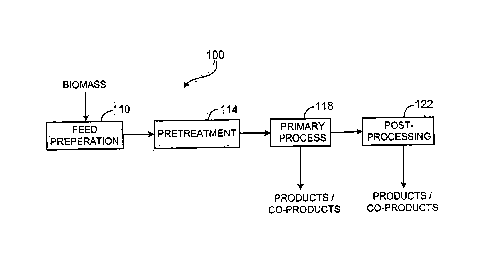
FIG. 1 shows a system 100 for converting biomass, particularly biomass with
significant cellulosic and lignocellulosic components and/or starchy
components,, into useful
products and. co-products. System 100 includes a feed preparation subsystem
HO, a
pretreatment subsystem 114, a primary process subsystem 118, and a post-
processing
subsystem 122. Feed preparation subsystem 110 receives biomass in its raw
form,
physically prepares the biomass for use as feedstock by downstream processes
(e.g., reduces
the size of and homogenizes the biomass), and stores the biomass both in its
raw and
feedstock forms. Biomass feedstock with significant cellulosic and/or
lignocellulosic
components, or starchy components can have a high average molecular weight and
crystallinity that can make processing the feedstock into useful products
(e.g., fermenting
the feedstock to produce ethanol) difficult. For example, others have used
acids, bases and
enzymes to process cellulosic, lignocellulosic or starchy feedstocks. As
described herein, in
some embodiments, such treatments are unnecessary, or arc necessary only in
small or
catalytic amounts.
Pretreatment subsystem 114 receives feedstock from the feed preparation
subsystem
110 and prepares the feedstock for use in primary production processes by, for
example,
reducing the average molecular weight and crystallinity of the feedstock.
Primary process
subsystem 118 receives pretreated feedstock from pretreatment subsystem 114
and produces
useful products (e.g., ethanol, other alcohols, pharmaceuticals, and/or food
products). In
some cases, the output of primary process subsystem 118 is directly useful
but, in other
casea, requires further processing provided by post-processing subsystem 122.
Post-
processing subsystem 122 provides further processing to product streams from
primary
process system 118 which require it (e.g., distillation and denaturation of
ethanol) as well as
32
CA 2993072 2018-01-26
=
WO 2005/140057 PCT/US2005/04i
treatment for waste streams from the other subsystems. In some cases, the co-
products of
subsystems 114, 118, 122 can also be directly or indirectly useful as
secondary products
and/or in increasing the overall efficiency of system 100. For example, post-
processing
subsystem 122 can produce treated water to be recycled for use as process
water in other
subsystems and/or can produce burnable waste which can be used as fuel for
boilers
producing steam and/or electricity.
The optimum size for biomass conversion plants is affected by factors
including
economies of scale and the type and availability of biomass used as feedstock.
Increasing
plant size tends to increase economies of scale associated with plant
processes. However,
le increasing plant size also tends to increase the costs (e.g.,
transportation costs) per unit of
feedstock. Studies analyzing these factors suggest that the appropriate size
for biomass
conversion plants can range from 1000 to 10,000 or more dried tons of
feedstock per day
depending at least in part on the type of feedstock used. The type of
feedstock can also
impact plant storage requirements with plants designed primarily for
processing feedstock
whose availability varies seasonally (e.g., corn stover) requiring more on- or
of-site
feedstock storage than plants designed to process feedstock whose availability
is relatively
steady (e.g., waste paper).
PHYSICAL PREPARATION
In some cases, methods of processing begin with a physical preparation of the
feedstock, e.g, size reduction of raw feedstock materials, such as by cutting,
grinding,
shearing, ball milling, nip-roll processing, or chopping. In some cases, the
material can
be reduced into particles using a hammermill, disk-refiner, or flaker. In some
cases,
loose feedstock (e.g., recycled paper, starchy materials, or switchgrass) is
prepared by
shearing or shredding. Screens and/or magnets can be used to remove oversized
or
undesirable objects such as, for example, rocks or nails from the feed stream.
Feed preparation systems can be configured to produce feed streams with
specific
characteristics such as, for example, specific maximum sizes, specific length-
to-width, or
specific surface areas ratios. As a part of feed preparation, the bulk density
of feedstocks
can be controlled (e.g., increased or decreased).
33
CA 2993072 2018-01-26
=
WO 2009/140057
PCTRIS2009/041942
,Size Reduction
In some embodiments, the material to be processed is in the form of a fibrous
material that includes fibers provided by shearing a fiber source. For
example, the
shearing can be performed with a rotary knife cutter.
For example, and by reference to FIG. 2, a fiber source 210 is sheared, e.g.,
in a
rotary knife cutter, to provide a first fibrous material 212. The first
fibrous material 212
is passed through a first screen 214 having an average opening size of 1.59 mm
or less
(1/16 inch, 0.0625 inch) to provide a second fibrous material 216. If desired,
fiber source
can be cut prior to the shearing, e.g., with a shredder. For example, when a
paper is used
as the fiber source, the paper can be first cut into strips that are, e.g.,
1/4- to 1/2-inch
wide, using a shredder, e.g., a counter-rotating screw shredder, such as those
manufactured by Munson (Utica, N.Y.). As an alternative to shredding, the
paper can be
reduced in size by cutting to a desired size using a guillotine cutter. For
example, the
guillotine cutter can be used to cut the paper into sheets that are, e.g., 10
inches wide by
12 inches long.
In some embodiments, the shearing of the fiber source and the passing of the
resulting first fibrous material through the first screen are performed
concurrently. The
shearing and the passing can also be performed sequentially, e.g., ma batch-
type process.
For example, a rotary knife cutter can be used to concurrently shear the fiber
source and screen the first fibrous material. Referring to FIG. 3, a rotary
knife cutter 220
includes a hopper 222 that can be loaded with a shredded fiber source 224
prepared by
shredding the fiber source. Shredded fiber source is sheared between
stationary blades
230 and rotating blades 232 to provide a first fibrous material 240. First
fibrous material
240 passes through screen 242, and the resulting second fibrous material 244
is captured
in bin 250. To aid in the collection of the second fibrous material, the bin
can have a
pressure below nominal atmospheric pressure, e.g., at least 10 percent below
nominal
atmospheric pressure, e.g., at least 25 percent below nominal atmospheric
pressure, at
least 50 percent below nominal atmospheric pressure, or at least 75 percent
below
nominal atmospheric pressure. In some embodiments, a vacuum source 252 is
utilized to
maintain the bin below nominal atmospheric pressure.
34
CA 29 930 72 2 0 1 8-0 1-26
=
WO 2009/140057 PCT/1.1820041942
Shearing can be advantageous for "opening up," "stressing," or even reducing
the
molecular weight of the fibrous materials, making the cellulose of the
materials more
susceptible to chain scission and/or reduction of crystallinity. The open
materials can
also be more susceptible to oxidation when irradiated.
The fiber source can be sheared in a dry state, a hydrated state (e.g., having
up to
ten percent by weight absorbed water), or in a wet state, e.g., having between
about 10
percent and about 75 percent by weight water. The fiber source can even be
sheared
while partially or fully submerged under a liquid, such as water, ethanol, or
isopropanol.
The fiber source can also be sheared in a gas (such as a stream or atmosphere
of
gas other than air), e.g., oxygen or nitrogen, or steam.
Other methods of making the fibrous materials include, e.g., stone grinding,
mechanical ripping or tearing, pin grinding, ball milling, nip-roll
processing, or air
attrition milling.
If desired, the fibrous materials can be separated, e.g., continuously or in
batches,
into fractions according to their length, width, density, material type, or
some
combination of these attributes.
For example, ferrous materials can be separated from any of the fibrous
materials
by passing a fibrous material that includes a ferrous material past a magnet,
e.g., an
electromagnet, and then passing the resulting fibrous material through a
series of screens,
each screen having different sized apertures.
The fibrous materials can also be separated, e.g., by using a high velocity
gas,
e.g., air. In such an approach, the fibrous materials are separated by drawing
off different
fractions, which can be characterized photonically, if desired. Such a
separation
apparatus is discussed, e.g., in Lindsey et al, U.S. Patent No. 6,883,667.
The fibrous materials can have a low moisture content, e.g., less than about
7.5, 5,
3,2.5, 2, 1.5, 1, or 0.5% by weight before processing. This material can be
irradiated
with a beam of particles, such as electrons or protons. The irradiation can be
immediately following preparation of the material, or after a moisture
reduction step, e.g.,
drying at approximately 105 C for 4-18 hours, so that the moisture content
is, e.g., less
than about 0.5% before use.
CA 2993072 2018-01-26
=
WO 2009/140057
PCT/US2009/041942
If desired, lignin can be removed from any of the fibrous materials that
include
lignin. Also, to aid in the breakdown of the materials that include the
cellulose, the
material can be treated prior to irradiation with heat, a chemical (e.g.,
mineral acid, base
or a strong oxidizer such as sodium hypochlorite) and/or an enzyme.
In some embodiments, the average opening size of the first screen is less than
0.79 mm (1/32 inch, 0.03125 inch), e.g., less than 0.51 mm (1/50 inch, 0.02000
inch),
less than 0.40 mm (1/64 inch, 0.015625 inch), less than 0.23 mm (0.009 inch),
less than
0.20 mm (1/128 inch, 0.0078125 inch), less than 0.18 mm (0.007 inch), less
than 0.13
nun (0.005 inch), or even less than less than 0.10 mm (1/256 inch, 0.00390625
inch).
The screen is prepared by interweaving monofilaments having an appropriate
diameter to
give the desired opening size. For example, the monofilaments can be made of a
metal,
e.g., stainless steel. As the opening sizes get smaller, structural demands on
the
monofilaments may become greater. For example, for opening sizes less than
0.40 mm,
it can be advantageous to make the screens from mono filaments made from a
material
other than stainless steel, e.g., titanium, titanium alloys, amorphous metals,
nickel,
tungsten, rhodium, rhenium, ceramics, or glass. In some embodiments, the
screen is
made from a plate, e.g., a metal plate, having apertures, e.g., cut into the
plate using a
laser. In some embodiments, the open area of the mesh is less than 52%, e.g.,
less than
41%, less than 36%, less than 31%, less than 30%.
In some embodiments, the second fibrous material is sheared and passed through
the first screen, or a different sized screen. In some embodiments, the second
fibrous
material is passed through a second screen having an average opening size
equal to or
less than that of first screen.
Referring to FIG. 4, a third fibrous material 220 can be prepared from the
second
fibrous material 216 by shearing the second fibrous material 216 and passing
the
resulting material through a second screen 222 having an average opening size
less than
the first screen 214.
Generally, the fibers of the fibrous materials can have a relatively large
average
length-to-diameter ratio (e.g., greater than 20-to-1), even if they have been
sheared more
than once. In addition, the fibers of the fibrous materials described herein
may have a
relatively narrow length and/or length-to-diameter ratio distribution.
36
CA 2993072 2018-01-26
=
WO 2009/140057 PCT/US/041942
As used herein, average fiber widths (i.e., diameters) are those determined
optically by randomly selecting approximately 5,000 fibers. Average fiber
lengths are
corrected length-weighted lengths. BET (Brunauer, Emmet and Teller) surface
areas are
multi-point surface areas, and porosities are those determined by mercury
porosimetry.
The average length-to-diameter ratio of the second fibrous material 14 can be,
e.g., greater than 8/1, 10/1, 15/1, 20/1, 25/1, or even greater than 50/1. An
average length
of the second fibrous material 14 can be, e.g., between about 0.5 mm and 2.5
mm, e.g.,
between about 0.75 mm and 1.0 mm, and an average width (i.e., diameter) of the
second
fibrous material 14 can be, e.g., between about 5 gm and 50 pun, e.g., between
about 10
pril an ci 301.4.m.
In some embodiments, a standard deviation of the length of the second fibrous
material 14 is less than 60 percent of an average length of the second fibrous
material 14,
e.g., less than 50 percent of the average length, less than 40 percent of the
average length,
less than 25 percent of the average length, less than 10 percent of the
average length, less
than 5 percent of the average length, or even less than 1 percent of the
average length.
In some embodiments, a BET surface area of the second fibrous material is
greater than 0.1 m2/g, e.g., greater than 0.25 m2/g, greater than 0.5 m2/g,
greater than 1.0
m2/g, greater than 1.5 m2/g, greater than 1.75 m2/g, greater than 5.0 m2/g,
greater than 10
m2/g, greater than 25 m2/g, greater than 35 m2/g, greater than 50m2/g, greater
than 60
m2/g, greater than 75 m2/g, greater than 100 m2/g, greater than 150 m2/g,
greater than 200
m2/g, or even greater than 250 m2/g. A porosity of the second fibrous material
14 can be,
e.g., greater than 20 percent, greater than 25 percent, greater than 35
percent, greater than
50 percent, greater than 60 percent, greater than 70 percent, e.g., greater
than 80 percent,
greater than 85 percent, greater than 90 percent, greater than 92 percent,
greater than 94
percent, greater than 95 percent, greater than 97.5 percent, greater than 99
percent, or
even greater than 99.5 percent.
In some embodiments, a ratio of the average length-to-diameter ratio of the
first
fibrous material to the average length-to-diameter ratio of the second fibrous
material is,
e.g., less than 1.5, e.g., less than 1.4, less than 1.25, less than 1.1, less
than 1.075, less
than 1.05, less than 1.025, or even_ substantially equal to 1.
37
CA 2993072 2018-01-26
=
WO 2009/140057 PCT/1JS2P/041.942
In particular embodiments, the second fibrous material is sheared again and
the
resulting fibrous material passed through a second screen having an average
opening size
less than the first screen to provide a third fibrous material. In such
instances, a ratio of
the average length-to-diameter ratio of the second fibrous material to the
average length-
to-diameter ratio of the third fibrous material can be, e.g., less than 1$,
e.g., less than 1.4,
less than 1.25, or even less than 1.1.
In some embodiments, the third fibrous material is passed through a third
screen
to produce a fourth fibrous material. The fourth fibrous material can be,
e.g., passed
through a fourth screen to produce a fifth material. Similar screening
processes can be
repeated as many times as desired to produce the desired fibrous material
having the
desired properties.
Densification
Densified materials can be processed by any of the methods described herein,
or
any material described herein, e.g., any fibrous material described herein,
can be
processed by any one or more methods described herein, and then densified as
described
herein.
A material, e.g., a fibrous material, having a low bulk density can be
densified to a
product having a higher bulk density. For example, a material composition
having a bulk
density of 0.05 g/ cm3 can be densified by sealing the fibrous material in a
relatively gas
impermeable structure, e.g., a bag made of polyethylene or a bag made of
alternating
layers of polyethylene and a nylon, and then evacuating the entrapped gas,
e.g., air, from
the structure. After evacuation of the air from the structure, the fibrous
material can have,
e.g., a bulk density of greater than 0.3 gjem3, e.g., 0.5 g/em3, 0.6 g/cm3,
0.7 gkm3 or
more, e.g., 0.85 gl cm3. After densification, the product can processed by any
of the
methods described herein, e.g., irradiated, e.g., with gamma radiation. This
can be
advantageous when it is desirable to transport the material to another
location, e.g., a
remote manufacturing plant, where the fibrous material composition can be
added to a
solution, e.g., to produce ethanol. After piercing the substantially gas
impermeable
structure, the densified fibrous material can revert to neatly its initial
bulk density, e.g.,
greater than 60 percent of its initial bulk density, e.g., 70 percent, 80
percent, 85 percent
38
CA 2 9 930 72 2 0 1 8 -0 1-26
S
WO 2009/140057
PCTM52009/041942
or more, e.g., 95 percent of its initial bulk density. To reduce static
electricity in the
fibrous material, an anti-static agent can be added to the material.
In some embodiments, the structure, e.g., bag, is formed of a material that
dissolves in a liquid, such as water. For example, the structure can be formed
from a
polyvinyl alcohol so that it dissolves when in contact with a water-based
system. Such
embodiments allow densified structures to be added directly to solutions that
include a
microorganism, without first releasing the contents of the structure, e.g., by
cutting.
Referring to FIG. 5, a biomass material can be combined with any desired
additives and a binder, and subsequently densified by application of pressure,
e.g., by
passing the material through a nip defined between counter-rotating pressure
rolls or by
passing the material through a pellet mill. During the application of
pressure, heat can
optionally be applied to aid in the densification of the fibrous material. The
densified
material can then be irradiated.
In some embodiments, the material prior to densification has a bulk density of
less
than 0.25 g/cm3, e.g., 0.20 g/cm3, 0.15 g/c1n3, 0.10 g/cm3, 0.05 g/cm3 or
less, e.g., 0.025
g/cm3. Bulk density is determined using ASTIvi D1895B. Briefly, the method
involves
filling a measuring cylinder of known volume with a sample and obtaining a
weight of
the sample. The bulk density is calculated by dividing the weight of the
sample in grams
by the known volume of the cylinder in cubic centimeters.
The preferred binders include binders that are soluble in water, swollen by
water,
or that has a glass transition temperature of less 25 C, as determined by
differential
scanning ealorimetry. By water-soluble binders, we mean binders having a
solubility of
at least about 0.05 weight percent in water. By water swellable binders, we
mean binders
that increase in volume by more than 0.5 percent upon exposure to water.
In some embodiments, the binders that are soluble or swollen by water include
a
functional group that is capable of forming a bond, e.g., a hydrogen bond,
with the fibers
of the fibrous material, e.g., cellulosic fibrous material. For example, the
functional
group can be a carboxylic acid group, a carboxylate group, a carbonyl group,
e.g., of an
aldehyde or a ketone, a sulfonic acid group, a sulfonate group, a phosphoric
acid group, a
phosphate group, an amide group, an amine group, a hydroxyl group, e.g., of an
alcohol,
and combinations of these groups, e.g., a carboxylic acid group and a hydroxyl
group.
39
CA 2993072 2018-01-26
=
WO 2009/140057 PCT/US2
09/041942
Specific monomeric examples include glycerin, glyoxal, ascorbic acid, urea,
glycine,
pentaerythritol, a monosaccharide or a disaccharide, citric acid, and tartaric
acid.
Suitable saccharides include glucose, sucrose, lactose, ribose, fructose,
mannose,
arabinose arid erythrose. Polymeric examples include polyglycols, polyethylene
oxide,
polyearboxylie acids, polyamides, polyamines and polysulfonic acids
polysulfonates.
Specific polymeric examples include polypropylene glycol (PPG), polyethylene
glycol
(PEG), polyethylene oxide, e.g., POLY0X , copolymers of ethylene oxide and
propylene
oxide, polyacrylic acid (PAA), polyacrylamide, polypeptides, polyethylenimine,
polyvinylpyridine, poly(sodium-4-styrenesulfonate) and poly(2-acrylamido-
methy1-1-
1 0 propanesulfonic acid).
In some embodiments, the binder includes a polymer that has a glass transition
temperature less than 25 C. Examples of such polymers include thermoplastic
elastomers (TPEs). Examples of TPEs include polyether block amides, such as
those
available under the tradename PEBAX , polyester elastomers, such as those
available
under the tradename HYTREL , and styrenic block copolymers, such as those
available
under the tradename ICRATON . Other suitable polymers having a glass
transition
temperature less than 25 C include ethylene vinyl acetate copolymer (EVA),
polyolefins,
e.g., polyethylene, polypropylene, ethylene-propylene copolymers, and
copolymers of
ethylene and alpha olefins, e.g., 1-octene, such as those available under the
tradename
ENGAGE . In some embodiments, e.g., when the material is a fiberized
polycoated
paper, the material is densified without the addition of a separate low glass
transition
temperature polymer.
In a particular embodiment, the binder is a lignin, e.g., a natural or
synthetically
modified lignin.
A suitable amount of binder added to the material, calculated on a dry weight
basis, is, e.g., from about 0.01 percent to about 50 percent, e.g., 0.03
percent, 0.05
percent, 0.1 percent, 0.25 percent, 0.5 percent, 1.0 percent, 5 percent, 10
percent or more,
e.g., 25 percent, based on a total weight of the densified material. The
binder can be
added to the material as a neat, pure liquid, as a liquid having the binder
dissolved
o therein, as a dry powder of the binder, or as pellets of the binder.
CA 2993072 2018-01-26
=
WO 2009/140057 PCT/US0041942
The densified fibrous material can be made in a pellet mill. Referring to FIG
6, a
pellet mill 300 has a hopper 301 for holding undensified material 310 that
includes
carbohydrate-containing materials, such as cellulose. The hopper communicates
with an
auger 312 that is driven by variable speed motor 314 so that undensified
material can be
transported to a conditioner 320 that stirs the undensified material with
paddles 322 that
are rotated by conditioner motor 330. Other ingredients, e.g., any of the
additives and/or
fillers described herein, can be added at inlet 332. If desired, heat may be
added while
the fibrous material is in the conditioner. After being conditioned, the
material passes
from the conditioner through a dump chute 340, and to another auger 342. The
dump
chute, as controlled by actuator 344, allows for unobstructed passage of the
material from
conditioner to auger. Auger is rotated by motor 346, and controls the feeding
of the
fibrous material into die and roller assembly 350. Specifically, the material
is introduced
into a hollow, cylindrical die 352, which rotates about a horizontal axis and
which has
radially extending die holes 250. Die 352 is rotated about the axis by motor
360, which
includes a horsepower gauge, indicating total power consumed by the motor.
Densified
material 370, e.g., in the form of pellets, drops from chute 372 and are
captured and
processed, such as by irradiation.
The material, after densification, can be conveniently in the form of pellets
or
chips having a variety of shapes. The pellets can then be irradiated. In some
embodiments, the pellets or chips are cylindrical in shape, e.g., having a
maximum
transverse dimension of, e.g., 1 ram or more, e.g., 2 mm, 3 mm, 5 mm, 8 mm, 10
min, 15
rumor more, e.g., 25 mm. Other convenient shapes include pellets or chips that
are
plate-like in form, e.g., having a thickness of 1 mm or more, e.g., 2 mm, 3
mm, 5 mm, 8
mm, 10 nun or more, e.g., 25 mm; a width of, e.g., 5 mm or more, e.g., 10 mm,
15 mm,
25 mm, 30 mm or more, e.g., 50 mm; and a length of 5 mm or more, e.g., 10 mm,
15 mm,
25 mm, 30 mm or more, e.g., 50 mm.
Referring now FIG. 7A-7D, pellets can be made so that they have a hollow
inside.
As shown, the hollow can be generally in-line with the center of the pellet
(FIG. 7B), or
out of line with the center of the pellet (FIG. 7C). Making the pellet hollow
inside can
increase the rate of dissolution in a liquid after irradiation.
41
CA 2993072 2018-01-26
=
WO 20091140057
PCTMS2009/041942
Referring now to FIG 7D, the pellet can have, e.g., a transverse shape that is
multi-lobal, e.g., tri-lobal as shown, or tetra-lobal, penta-lobal, hexa-lobal
or deca-lobal.
Making the pellets in such transverse shapes can also increase the rate of
dissolution in a
solution after irradiation.
5 Alternatively, the densified material can be in any other desired
form, e.g., the
densified material can be in the form of a mat, roll or bale.
Examples
In one example, half-gallon juice cartons made of un-printed white Kraft board
having a bulk density of 20 lb/ft3 can be used as a feedstock. Cartons can be
folded flat
10 and then fed into a shredder to produce a confetti-like material having
a width of between
0.1 inch and 0.5 inch, a length of between 0.25 inch and 1 inch and a
thickness equivalent
to that of the starting material (about 0.075 inch). The confetti-like
material can be fed to
a rotary knife cutter, which shears the confetti-like pieces, tearing the
pieces apart and
releasing fibrous material.
15 In some cases, multiple shredder-shearer trains can be arranged in
series with
output. In one embodiment, two shredder-shearer trains can be arranged in
series with
output from the first shearer fed as input to the second shredder. In another
embodiment,
three shredder-shearer trains can be arranged in series with output from the
first shearer
fed as input to the second shredder and output from the second shearer fed as
input to the
20 third shredder. Multiple passes through shredder-shearer trains are
anticipated to
decrease particle size and increase overall surface area within the
feedstream.
In another example, fibrous material produced from shredding and shearing
juice
cartons can be treated to increase its bulk density. In some cases, the
fibrous material can
be sprayed with water or a dilute stock solution of POLYOXTm WSR N10
(polyethylene
25 oxide) prepared in water. The wetted fibrous material can then be
processed through a
pellet mill operating at room temperature. The pellet mill can increase the
bulk density of
the feedstream by more than an order of magnitude.
42
CA 2 9 930 72 2 0 1 8 -0 1-2 6
4111
=
WO 2009/140057
PCT/US2009/041942
PRETREATMENT
Physically prepared feedstock can be pretreated for use in primary production
processes by, for example, reducing the average molecular weight and
crystallinity of the
feedstock and/or increasing the surface area and/or porosity of the feedstock.
In some embodiments, the cellulosic and/or lignocellulosic material includes a
first cellulose having a first number average molecular weight and the
resulting
carbohydrate includes a second cellulose having a second number average
molecular
weight lower than the first number average molecular weight. For example, the
second
number average molecular weight is lower than the first number average
molecular
weight by more than about twenty-five percent, e.g., 2x, 3x, 5x, 7x, 10x, 25x,
even 100x
reduction.
In some embodiments, the first cellulose has a first crystallinity and the
second
cellulose has a second crystallinity lower than the first crystallinity, such
as lower than
about two, three, five, ten, fifteen or twenty-five percent lower.
In some embodiments, the first cellulose has a first level of oxidation and
the
second cellulose has a second level of oxidation higher than the first level
of oxidation,
such as two, three, four, five, ten or even twenty-five percent higher.
Pretreatment processes can include one or more of irradiation, sonication,
oxidation, pyrolysis, and steam explosion. The various pretreatment systems
and
methods can be used in combinations of two, three, or even four of these
technologies.
.Pretreatment Combinations
In some embodiments, biomass can be processed by applying two or more of any
of the processes described herein, such as two, three, four or more of
radiation, sonication
(or any other disruption technique described herein, e.g., treatment with a
rotor-stator
disruptor), oxidation, pyrolysis, and steam explosion either with or without
prior,
intermediate, or subsequent feedstock preparation as described herein. The
processes can
be applied to the biomass in any order or concurrently For example, a
carbohydrate can
be prepared by applying radiation, sonication, oxidation, pyrolysis, and,
optionally, steam
explosion to a cellulosic and/or lignocellulosic material (in any order or
concurrently).
The provided carbohydrate-containing material can then be converted by one or
more
microorganisms, such as bacteria, yeast, or mixtures of yeast and bacteria, to
a number of
43
CA 2 9 9 3 0 7 2 2 0 1 8-0 1-26
W. 2009/140057
PCMS241/041942
desirable products, as described herein. Multiple processes can provide
materials that can
be more readily utilized by a variety of microorganisms because of their lower
molecular
weight, lower crystallinity, and/or enhanced solubility. Multiple processes
can provide
synergies and can reduce overall energy input required in comparison to any
single
process.
For example, in some embodiments, feedstocks are provided that include a
carbohydrate that is produced by a process that includes irradiating and
sonicating,
irradiating and oxidizing, irradiating and pyrolyzing, or irradiating and
steam-exploding
(in either order or concurrently) a cellulosic and/or a lignocellulosic
material. The
provided feedstock can then be contacted with a microorganism having the
ability to
convert at least a portion, e.g., at least about I percent by weight, of the
feedstock to the
product, such as the combustible fuel.
Pretreatment Conditions
In some embodiments, the process does not include hydrolyzing the cellulosic
and/or lignocellulosic material, such as with an acid, e.g., a mineral acid,
such as
hydrochloric or sulfuric acid, an. enzyme or a base. If desired, some or none
of the
feedstock can include a hydrolyzed material. For example, in some embodiments,
at least
about seventy percent by weight of the feedstock is an unhydrolyzed material,
e.g., at
least at 95 percent by weight of the feedstock is an unb.ydrolyzed material.
In some
embodiments, substantially all of the feedstock is an unhycholyzed material.
For
example, treatment with alkali can be avoided.
Any feedstock or any reactor or fermentor charged with a feedstock can include
a
buffer, such as sodium bicarbonate, ammonium chloride or Tris; an electrolyte,
such as
potassium chloride, sodium chloride, or calcium chloride; a growth factor,
such as biotin
and/or a base pair such as uracil or an equivalent thereof; a surfactant, such
as Tween or
polyethylene glycol; a mineral, such as such as calcium, chromium, copper,
iodine, iron,
selenium, or zinc; or a chelating agent, such as ethylene diamine, ethylene
diamine
tetraacetic acid (EDTA) (or its salt form, e.g., sodium or potassium EDTA), or
dimereaprol.
44
CA 2993072 2018-01-26
=
=
WO 2009/140057
PC'T/US9/041942
When radiation is utilized, it can be applied to any sample that is dry or
wet, or
even dispersed in a liquid, such as water. For example, irradiation can be
performed on
cellulosic and/or lignocellulosic material in which less than about 25 percent
by weight of
the cellulosic and/or lignocellulosic material has surfaces wetted with a
liquid, such as
water. In some embodiments, irradiating is performed on cellulosic and/or
lignocellulosic material in which substantially none of the cellulosic and/or
lignocellulosic material is wetted with a liquid, such as water.
In some embodiments, any processing described herein occurs with the
cellulosic
and/or lignocellulosic material remaining dry as acquired or after the
material has been
to dried, e.g., using heat and/or reduced pressure. For example, in
some embodiments, the
cellulosic and/or lignocellulosic material has less than about five percent by
weight
retained water, measured at 25 C and at fifty percent relative humidity.
The feedstock can be treated so that it has a low moisture content, e.g., less
than
about 7.5, 5, 3, 2.5, 2, 1.5, 1, or 0.5% by weight. This material can be
irradiated with a
15 beam of particles, such as electrons or protons. The irradiation
can be immediately
following preparation of the material or after a moisture reduction step,
e.g., drying at
approximately 105 C for 4-18 hours.
If desired, a swelling agent, as defined herein, can be utilized in any
process
described herein. In some embodiments, when a cellulosic and/or
lignocellulosic
20 material is processed using radiation, less than about 25 percent
by weight of the
cellulosic and/or lignocellulosic material is in a swollen state, the swollen
state being
characterized as having a volume of more than about 2.5 percent higher than an
unswolIen state, e.g., more than 5.0, 7.5, 10, or 15 percent higher than the
unswolIen
state. In specific embodiments when radiation is utilized, the cellulosic
and/or
25 lignocellulosic material includes a swelling agent, and swollen
cellulosic and/or
lignocellulosic receives a dose of less than about 10 Mrad. In other
embodiments, when
radiation is utilized on a cellulosic and/or lignocellulosic material,
substantially none of
the cellulosic and/or lignocellulosic material is in a swollen state.
In some embodiments, no chemicals, e.g., no swelling agents, are added to the
30 biomass prior to irradiation. For example, in some of these
embodiments no alkaline
substances (such as sodium hydroxide, potassium hydroxide, lithium hydroxide
and
CA 2993072 2018-01-26
WO 2009/140057
PCT/US1P9/041942
ammonium hydroxides), acidifying agents (such as mineral acids (e.g., sulfuric
acid,
hydrochloric acid and phosphoric acid)), salts, such as zinc chloride, calcium
carbonate,
sodium carbonate, benzyltrimethylammonium sulfate, or basic organic amities,
such as
ethylene diarnine, are added prior to irradiation or other processing. In some
cases, no
additional water is added. For example, the biomass prior to processing can
have less
than 0.5 percent by weight added chemicals, e.g., less than 0.4, 0.25, 0.15 or
0.1 percent
by weight added chemicals. In some instances, the biomass has no more than a
trace,
e.g., less than 0.05 percent by weight added chemicals, prior to irradiation.
In other
instances, the biomass prior to irradiation has substantially no added
chemicals or
swelling agents. Avoiding the use of such chemicals can also be extended
throughout
processing, e.g., at all times prior to fermentation, or at all times.
When radiation is utilized in any process, it can be applied while the
cellulosic
and/or lignocellulosic is exposed to air, oxygen-enriched air, or even oxygen
itself, or
blanketed by an inert gas such as nitrogen, argon, or helium. When maximum
oxidation
is desired, an oxidizing environment is utilized, such as air or oxygen. The
distance from
the radiation source can also be optimized to maximize reactive gas formation,
e.g.,
ozone and/or oxides of nitrogen.
When radiation is utilized, it may be applied to biomass, such as cellulosic
and/or
lignocellulosic material, under a pressure of greater than about 2.5
atmospheres, such as
greater than 5, 10, 15, 20 or even greater than about 50 atmospheres.
When the process includes radiation, the irradiating can be performed
utilizing an
ionizing radiation, such as gamma rays, x-rays, energetic ultraviolet
radiation, such as
ultraviolet C radiation having a wavelength of from about 100 nm to about 280
nrn, a
beam of particles, such as a beam of electrons, slow neutrons or alpha
particles. In some
embodiments, irradiating includes two or more radiation sources, such as gamma
rays
and a beam of electrons, which can be applied in either order or concurrently.
Any processing technique described herein can be used at a pressure above or
below normal, earth-bound atmospheric pressure. For example, any process that
utilizes
radiation, sonication, oxidation, pyrolysis, steam explosion, or combinations
of any of
these processes to provide materials that include a carbohydrate can be
performed under
high pressure, which can increase reaction rates. For example, any process or
46
CA 2993072 2018-01-26
WO 2009/140057 PCT/U/041942
combination of processes can be performed at a pressure greater than about
normal
atmospheric pressure, e.g., at a pressure of greater than about 25 MPa, e.g.,
greater than
50 MPa, 75 MPa, 100 MPa, 150 MPa, 200 MPa, 250 MPa, 350 MPa, 500 MPa, 750
MPa, 1,000 MPa, or greater than 1,500 MPa.
Radiation Treatment
One or more irradiation processing sequences can be used to process raw
feedstock from a wide variety of different sources to extract useful
substances from the
feedstock, and to provide partially degraded organic material which functions
as input to
further processing steps and/or sequences. Irradiation can reduce the
molecular weight
le and/or crystallinity of feedstock. In some embodiments, energy deposited
in a material
that releases an electron from its atomic orbital is used to irradiate the
materials. The
radiation may be provided by 1) heavy charged particles, such as alpha
particles or
protons, 2) electrons, produced, for example, in beta decay or electron beam
accelerators,
or 3) electromagnetic radiation, for example, gamma rays, x rays, or
ultraviolet rays. In
one approach, radiation produced by radioactive substances can be used to
irradiate the
feedstock. In some embodiments, any combination in any order or concurrently
of (1)
through (3) may be utilized. In another approach, electromagnetic radiation
(e.g.,
produced using electron beam emitters) can be used to irradiate the feedstock.
The doses
applied depend on the desired effect and the particular feedstock. For
example, high
doses of radiation can break chemical bonds within feedstock components and
low doses
of radiation can increase chemical bonding (e.g., cross-linking) within
feedstock
components. In some instances when chain scission is desirable and/or polymer
chain
functionalization is desirable, particles heavier than electrons, such as
protons, helium
nuclei, argon ions, silicon ions, neon ions carbon ions, phoshorus ions,
oxygen ions or
nitrogen ions can be utilized. When ring-opening chain scission is desired,
positively
charged particles can be utilized for their Lewis acid properties for enhanced
ring-
opening chain scission. For example, when oxygen-containing functional groups
are
desired, irradiation in the presence of oxygen or even irradiation with oxygen
ions can be
performed. For example, when nitrogen-containing functional groups are
desirable,
irradiation in the presence of nitrogen or even irradiation with nitrogen ions
can be
performed.
47
CA 2993072 2018-01-26
=
WO 2009/140057
PCT/US2009/041942
Referring to FIG. 8, in one method, a first material 2 that is or includes
cellulose
having a first number average molecular weight (TMO is irradiated, e.g., by
treatment
with ionizing radiation (e.g., in the form of gamma radiation, X-ray
radiation, 100 nm to
280 nm ultraviolet (UV) light, a beam of electrons or other charged particles)
to provide a
second material 3 that includes cellulose having a second number average
molecular
weight (TK,t2) lower than the first number average molecular weight. The
second
material (or the first and second material) can be combined with a
microorganism (e.g., a
bacterium or a yeast) that can utilize the second and/or first material to
produce a product,
e.g., a fuel 5 that is or includes hydrogen, an alcohol (e.g., ethanol or
butanol, such as n-,
sec- or t-butanol), an organic acid, a hydrocarbon or mixtures of any of
these.
Since the second material 3 has cellulose having a reduced molecular weight
relative to the first material, and in some instances, a reduced crystallinity
as well, the
second material is generally more dispersible, swellable and/or soluble in a
solution
containing a microorganism. These properties make the second material 3 more
susceptible to chemical, enzymatic and/or biological attack relative to the
first material 2,
which can greatly improve the production rate and/or production level of a
desired
product, e.g., ethanol. Radiation can also sterilize the materials.
In some embodiments, the second number average molecular weight (MN2) is
lower than the first number average molecular weight (TKO by more than about
10
percent, e.g., 15, 20, 25, 30, 35, 40, 50 percent, 60 percent, or even more
than about 75
percent.
In some instances, the second material has cellulose that has as crystallinity
(C2)
that is lower than the crystallinity (CO of the cellulose of the first
material. For
example, (TC2) can be lower than (TCt) by more than about 10 percent, e.g.,
15,20, 25,
30, 35, 40, or even more than about 50 percent.
In some embodiments, the starting crystallinity index (prior to irradiation)
is from
about 40 to about 87.5 percent, e.g., from about 50 to about 75 percent or
from about 60
to about 70 percent, and the crystallinity index after irradiation is from
about 10 to about
50 percent, e.g., from about 15 to about 45 percent or from about 20 to about
40 percent
However, in some embodiments, e.g., after extensive irradiation, it is
possible to have a
48
CA 2993072 2018-01-26
=
WO 2009/140057
PCT/US2ti /041942
crystallinity index of lower than 5 percent In some embodiments, the material
after
irradiation is substantially amorphous.
In some embodiments, the starting number average molecular weight (prior to
irradiation) is from about 200,000 to about 3,200,000, e.g., from about
250,000 to about
1,000,000 or from about 250,000 to about 700,000, and the number average
molecular
weight after irradiation is from about 50,000 to about 200,000, e.g., from
about 60,000 to
about 150,000 or from about 70,000 to about 125,000. However, in some
embodiments,
= e.g., after extensive irradiation, it is possible to have a number
average molecular weight
= of less than about 10,000 or even less than about 5,000.
In some embodiments, the second material can have a level of oxidation (T02)
that is higher than the level of oxidation (T01) of the first material. A
higher level of
oxidation of the material can aid in its dispersibility, swellability and/or
solubility, further
enhancing the materials susceptibility to chemical, enzymatic or biological
attack. In
some embodiments, to increase the level of the oxidation of the second
material relative
to the first material, the irradiation is performed under an oxidizing
environment, e.g.,
under a blanket of air or oxygen, producing a second material that is more
oxidized than
the first material. For example, the second material can have more hydroxyl
groups,
aldehyde groups, ketone groups, ester groups or carboxylic acid groups, which
can
increase its hydrophilicity.
Ionizing Radiation
Each form of radiation ionizes the biomass via particular interactions, as
determined by the energy of the radiation. Heavy charged particles primarily
ionize
matter via Coulomb scattering; furthermore, these interactions produce
energetic
electrons that may further ionize matter. Alpha particles are identical to the
nucleus of a
helium atom and are produced by the alpha decay of various radioactive nuclei,
such as
isotopes of bismuth, polonium, astatine, radon, francium, radium, several
aotinides, such
as actinium, thorium, uranium, neptunium, curium, californium, americium, and
= plutonium.
When particles are utilized, they can be neutral (uncharged), positively
charged or
negatively charged. When charged, the charged particles can bear a single
positive or
negative charge, or multiple charges, e.g., one, two, three or even four or
more charges.
49
CA 2993072 2018-01-26
=
WO 2009/140057
PC171152009/041942
In instances in which chain scission is desired, positively charged particles
may be
desirable, in part, due to their acidic nature. When particles are utilized,
the particles can
have the mass of a resting electron, or greater, e.g., 500, 1000, 1500, or
2000 or more
times the mass of a resting electron. For example, the particles can have a
mass of from
about 1 atomic unit to about 150 atomic units, e.g., from about 1 atomic unit
to about 50
atomic units, or from about Ito about 25, e.g., 1, 2, 3, 4, 5, 10, 12 or 15
amu.
Accelerators used to accelerate the particles can be electrostatic DC,
electrodynamic DC,
RF linear, magnetic induction linear or continuous wave. For example,
cyclotron type
accelerators are available from IBA, Belgium, such as the Rhodotron system,
while DC
to type accelerators are available from RD/, now IBA Industrial, such as
the Dynatnitrone.
Ions and ion accelerators are discussed in Introductory Nuclear Physics,
Kenneth. S.
Krane, John Wiley & Sons, Inc. (1988), Krsto Prelec, FIZIKA B 6 (1997) 4, 177-
206, a
copy of which is attached hereto as Appendix B, Chu, William T., "Overview of
Light-
Ion Beam Therapy", Columbus-Ohio, 1CRU-IAEA Meeting, 18-20 March 2006, a copy
of which is attached hereto as Appendix C, Iwata, Y. et al., "Alternating-
Phase-Focused
IH-DTL for Heavy-Ion Medical Accelerators", Proceedings of EPAC 2006,
Edinburgh,
Scotland, a copy of which is attached hereto as Appendix D, and Leitner, C.M.
et al.,
"Status of the Superconducting ECR Ion Source Venus", Proceedings of FPAC
2000,
Vienna, Austria, a copy of which is attached hereto as Appendix E.
Electrons interact via Coulomb scattering and bremsstrahlung radiation
produced
by changes in the velocity of electrons. Electrons may be produced by
radioactive nuclei
that undergo beta decay, such as isotopes of iodine, cesium, technetium, and
iridium.
Alternatively, an electron gun can be used as an electron source via
thermionic emission.
Electromagnetic radiation interacts via three processes: photoelectric
absorption,
Compton scattering, and pair production. The dominating interaction is
determined by
the energy of the incident radiation and the atomic number of the material.
The
summation of interactions contributing to the absorbed radiation in cellulosic
material
can be expressed by the mass absorption coefficient.
Electromagnetic radiation is subclassified as gamma rays, x rays, ultraviolet
rays,
infrared rays, microwaves, or radiowaves, depending on its wavelength.
CA 2993072 2018-01-26
=
1983-16(5)
For example, gamma radiation can be employed to irradiate the rnatena s. =
Referring to FIGS. 9 and 10 (an enlarged view of region R), a gamma irradiator
10
includes gamma radiation sources 408, e.g., ."Co pellets, a working table 14
for holding
the materials to be irradiated and storage 16, e.g., made of a plurality iron
plates, all of
which are housed in a conorete containment chamber (vault) 20 that includes a
maze
entranceway 22 beyond a lead-lined door 26. Storage 16 includes a plurality of
channels- '
30, e.g., sixteen or more channels, allowing the gamma radiation sources to
pass through
storage on their way proximate the working table.
In operation, the sample to be irradiated is placed on a working table. The
irradiator is configured to deliver the desired dose rate and monitoring
equipment is
connected to an experimental block 31. The operator then leaves the
containment
chamber, passing through the maze entranceway and through the lead-lined door.
The
operator mans a control pane132, instructing a computer 33 to lift the
radiation sources
12 into working position using cylinder 36 attached to a hydraulic pump 40.
-15. Gamma radiation has the advantage of a significant penetration depth
into a
variety of material in the sample. Sources of gamma rays include radioactive
nuclei, such
as isotopes of cobalt, calcium, techniciurn, chromium, gallium, indium,
iodine, iron,
krypton, samarium, selenium, sodium, thulium, and xenon.
Sources of x rays include electron beam-collision with metal targets, such as-
tungsten or molybdenum or alloys, or compact light sources, such is those
produced
commercially by Lyncean.
Sources for ultraviolet radiation include deuterium or cadmium lamps. .
= Sources for infrared radiation include sapphire, zinc, or selenide window
ceramic
=
lamps. =
Sources for microwaves include klystrons, Slevin type RF sources, or atom beam
sources that employ hydrogen, oxygen, or nitrogen gases.
= Various other irradiating devices may be used in the methods disclosed
herein,
including field ionization sOurces, electrostatic ion separators, field
ionization generators,
thermionic emission sources, micmwave discharge ion sources, recirculating or
static
accelerators, dynamic linear accelerators, van'de Graaff accelerators, and
folded tandem '
accelerators. Such devices are disclosed, for example, in international.
Publication
Nos. WO 2009/154876 and WO 2009/134745.
51
CA 2993072 2018-01-26
= ..)3983-16(S)
Electron Beam
In some embodiments, a beam of electrons is used as the radiation source. A
beam of electrons has the advantages of high dose rates (e.g., 1, 5, or even
10 Mrad per
second), high throughput, less containment, and less confinement equipment.
Electron
beams can also have up to 80 percent electrical efficiency, allowing for a low
energy
usage, which can translate into a low cost of operation and low greenhouse gas
emissions
corresponding to the small amount of energy used. Electrons can also be more
efficient
to at causing chain scission. In addition, electrons having energies of 4-
10 MeV can have a
penetration depth of 5 to 30 mm or more, such as 40 mm. In low bulk density
materials,
such as many of the materials described herein, e.g., materials having a bulk
density of
less than about 0.5 g/cm3, electrons having energies in the 4-10 MeV range can
penetrate
4-8 inches or even more.
Electron beams can be generated, e.g., by electrostatic generators, cascade
generators, transformer generators, low energy accelerators with a'scanning
system, low
energy accelerators with a linear cathode, linear accelerators, and pulsed
accelerators.
Electrons as an ionizing radiation source can be useful, e.g., for relatively
thin piles of
materials, e.g., less than 0.5 inch, e.g., less than 0.4 inch, 0.3 inch, 0.2
inch, or less than
0.1 inch.. In some embodiments, the energy of each electron of the electron
beam is from
about 0.3 MeV to about 2.0 MeV (million electron volts), e.g., from about 0.5
MeV to
about 1.5 MeV, or from about 0.7 MeV to about 1.25 MeV.
FIG. 11 shows a process flow diagram 3000 that includes various steps in an
electron beam irradiation feedstock pretreatment sequence. In first step 3010,
a supply of
, dry feedstock is received from a feed source. As discussed above, the dry
feedstock from
the feed source may be pre-processed prior to delivery to the electron beam
irradiation
devices. For example, if the feedstock is derived from plant sources, certain
portions of
the plant material may be removed prior to collection of the plant material
and/or before
the plant material is delivered by the feedstock transport device.
Alternatively, or in
addition, as expressed in optional step 3020, the biomass feedstock can be
subjected to
52
CA 2993072 2018-01-26
=
W. 2009/140057
PCT/E111/041942
mechanical processing (e.g., to reduce the average length of fibers in the
feedstock) prior
to delivery to the electron beam irradiation devices.
In step 3030, the dry feedstock is transferred to a feedstock transport device
(e.g.,
a conveyor belt) and is distributed over the cross-sectional width of the
feedstock
transport device approximately uniformly by volume. This can be accomplished,
for
example, manually or by inducing a localized vibration motion at some point in
the
feedstock transport device prior to the electron beam irradiation processing.
In some embodiments, a mixing system introduces a chemical agent 3045 into the
feedstock in an optional process 3040 that produces a slurry. Combining water
with the
le processed feedstock in mixing step 3040 creates an aqueous feedstock
slurry that may be
transported through, for example, piping rather than using, for example, a
conveyor belt.
The next step 3050 is a loop that encompasses exposing the feedstock (in dry
or
slurry form) to electron beam radiation via one or more (say, A)) electron
beam irradiation
devices. The feedstock slurry is moved through each of the N"showers" of
electron
beams at step 3052. The movement may either be at a continuous speed through
and
between the showers, or there may be a pause through each shower, followed by
a sudden
movement to the next shower. A small slice of the feedstock slurry is exposed
to each
shower for some predetermined exposure time at step 3053.
Electron beam irradiation devices may be procured commercially from Ion Beam
Applications, Louvain-la-Neuve, Belgium or the Titan Corporation, San. Diego,
CA.
Typical electron energies can be 1 MeV, 2 MeV, 4.5 MeV, 7.5 MeV, or 10 MeV.
Typical electron beam irradiation device power can be I kW, 5 kW, 10 kW, 20
kW, 50
kW, 100 kW, 250 kW, or 500 kW. Effectiveness of depolymerization of the
feedstock
slurry depends on the electron energy used and the dose applied, while
exposure time
depends on the power and dose. Typical doses may take values of 1 kGy, 5 kGy,
10 kGy,
20 kGy, 50 kGy, 100 kGy, or 200 kGy.
Tradeoffs in considering electron beam irradiation device power specifications
include cost to operate, capital costs, depreciation, and device footprint.
Tradeoffs in
considering exposure dose levels of electron beam irradiation would be energy
costs and
environment, safety, and health (ESH) concerns. Typically, generators are
housed in a
vault, e.g., of lead or concrete. Tradeoffs in considering electron energies
include energy
53
CA 2993072 2018-01-26
=
WO 2009/140057 POT/US2009/041942
costs; here, a lower electron energy may be advantageous in encouraging
depolyrnerization of certain feedstock slurry (see, for example, Bouchard, et
al, Cellulose
(2006) 13: 601-610).
It may be advantageous to provide a double-pass of electron beam irradiation
in
order to provide a more effective depolymerization process. For example, the
feedstock
transport device could direct the feedstock (in dry or slurry form) underneath
and in a
reverse direction to its initial transport direction. Double-pass systems can
allow thicker
feedstock slurries to be processed and can provide a more unifonm
depolymerization
through the thickness of the feedstock slurry.
The electron beam irradiation device can produce either a fixed beam or a
scanning beam. A scanning beam may be advantageous with large scan sweep
length
and high scan speeds, as this would effectively replace a large, fixed beam
width.
Further, available sweep widths of 0.5 in, 1m, 2 m or more are available.
Once a portion of feedstock slurry has been transported through the N electron
beam irradiation devices, it may be necessary in some embodiments, as in step
3060, to
mechanically separate the liquid and solid components of the feedstock slurry.
In these
embodiments, a liquid portion of the feedstock slurry is filtered for residual
solid particles
and recycled back to the slurry preparation step 3040. A solid portion of the
feedstock
slurry is then advanced on to the next processing step 3070 via the feedstock
transport
device. In other embodiments, the feedstock is maintained in slurry form for
further
processing.
Heavy Ion Particle Beams
Particles heavier than electrons can be utilized to irradiate carbohydrates or
materials that include carbohydrates, e.g., cellulosic materials,
lignocellulosic materials,
starchy materials, or mixtures of any of these and others described herein.
For example,
protons, helium nuclei, argon ions, silicon ions, neon ions carbon ions,
phosliorus ions,.
oxygen ions or nitrogen ions can be utilized. In some embodiments, particles
heavier
than electrons can induce higher amounts of chain scission. In some instances,
positively
charged particles can induce higher amounts of chain scission than negatively
charged
particles due to their acidity.
54
CA 2993072 2018-01-26
=
W. 2009/140057
PCIAIS2009/041942
Heavier particle beams can be generated, e.g., using linear accelerators or
cyclotrons. In some embodiments, the energy of each particle of the beam is
from about
1.0 MeV/atomic unit to about 6,000 MeV/atomic unit, e.g., from about 3 MeV/
atomic
unit to about 4,800 MeV/atomic unit, or from about 10 MeV/atomic unit to about
1,000
MeV/atomic unit.
Electromagnetic Radiation
In embodiments in which the irradiating is performed with electromagnetic
radiation, the electromagnetic radiation can have, e.g., energy per photon (in
electron
volts) of greater than 102 eV, e.g., greater than 103, 104, 105, 106, or even
greater than 107
eV. In some embodiments, the electromagnetic radiation has energy per photon
of
between 104 and 107, e.g., between 105 and 106 eV. The electromagnetic
radiation can
have a frequency of, e.g., greater than 1016 hz, greater than 1017 hz, 1018,
1019, 1020, or
even greater than 1021 hz. In some embodiments, the electromagnetic radiation
has a
frequency of between 1018 and 1022hz, e.g., between 1019 to 1021 hz.
Doses
In some embodiments, the irradiating (with any radiation source or a
combination
of sources) is performed until the material receives a dose of at least 0.05
Mrad, e.g., at
least 0.1, 0.25, 1.0, 2.5, 5.0, or 10_0 Mrad. In some embodiments, the
irradiating is
performed until the material receives a dose of between 1.0 Mrad and 6.0 Mrad,
e.g.,
between 1.5 Mrad and 4.0 Mrad. In other embodiments, irradiating is performed
at a
dose between about 0.1 MRad and about 10 MRad, e.g., between about 0.25 MRad
and
about 9 MRad, between about 0.5 MRad and about 7.5 MRad or between. about 0.75
MRad and about 5 MRad.
In some embodiments, the irradiating is performed at a dose rate of between
5.0
and 1500.0 kilorads/hour, e.g., between 10.0 and 750,0 kilorads/hour or
between 50.0 and
350.0 kilorads/hours.
In some embodiments, two or more radiation sources are used, such as two or
more ionizing radiations. For example, samples can be treated, in any order,
with a beam
of electrons, followed by gamma radiation and UV light having wavelengths from
about
CA 2993072 2018-01-26
4111 =
WO 2009/140057 PCT/US2009/041942
100 nm to about 280 nm. In some embodiments, samples are treated with three
ionizing
radiation sources, such as a beam of electrons, gamma radiation, and energetic
UV light.
In one example of the use of radiation as a pretreatment, half-gallon juice
cartons
made of un-printed polycoated white Kraft board having a bulk density of 20
lb/ft3 are
used as a feedstock. cartons are folded flat and then fed into a sequence of
three
shredder-shearer trains arranged in series with output from the first shearer
fed as input to
the second shredder, and output from the second shearer fed as input to the
third shredder.
The fibrous material produced by the shredder-shearer train can be sprayed
with water
and processed through a pellet mill operating at room temperature. The
densified pellets
can be placed in a glass ampoule which is evacuated under high vacuum and then
back-
filled with argon gas. The ampoule is sealed under argon. Alternatively, in
another
example, the ampoule is sealed under an atmosphere of air. The pellets in the
ampoule
are irradiated with gamma radiation for about 3 hours at a dose rate of about
1 Mrad per
hour to provide an irradiated material in which the cellulose has a lower
molecular weight
than the starting material.
=Additiveszto'E'nhance Molacular.Waiqiii Breakdown Durina
In some embodiments, prior to irradiation, various materials, e.g., solids or
liquids, can be added to the biomass to enhance molecular weight reduction. In
those
instances in which a liquid is utilized, the liquid can be in contact with
outer surfaces of
the biomass and/or the liquid can be in interior portions of the biomass,
e.g., infused into
the biomass.
For example, the material can be a neutral weak base, such as alanine,
ammonia,
ammonia/water mixture, e.g., 25 percent by weight ammonia in water, water,
methyl
amine, dimethyl amine, trimethyl amine, pyridine, or a anionic base, such as a
salt of
acetic acid (e.g., sodium acetate), sodium carbonate, sodium bicarbonate or a
salt of an
ion of hydrogen sulfide (e.g., sodium hydrosulfide).
Alternatively, the material can be a neutral weak acid, such as formic acid,
acetic
acid, trichloroacetic acid, water, hydrogen sulfide or a cationic acid, such
as an
ammonium salt.
56
CA 2993072 2018-01-26
W. 2009/140057 PCT/U,041942
Quenching and Controlled Functionalization of Biomass
After treatment with one or more ionizing radiations, such as photonic
radiation
(e.g., X-rays or gamma-rays), e-beam radiation or particles heavier than
electrons that are
positively or negatively charged (e.g., protons or carbon ions), any of the
carbohydrate-
s containing materials or mixtures described herein become ionized; that
is, they include
radicals at levels that are detectable with an electron spin resonance
spectrometer. The
current limit of detection of the radicals is about 1014 spins at room
temperature. After
ionization, any biomass material that has been ionized can be quenched to
reduce the
level of radicals in the ionized biomass, e.g., such that the radicals are no
longer
0 detectable with the electron spin resonance spectrometer. For example,
the radicals can
be quenched by the application of a sufficient pressure to the biomass and/or
by utilizing
a fluid in contact with the ionized biomass, such as a gas or liquid, that
reacts with
(quenches) the radicals. Using a gas or liquid to at least aid in the
quenching of the
radicals can be used to functionafize the ionized biomass with a desired
amount and kind
15 of functional groups, such as carboxylic acid groups, enoI groups,
aldehyde groups, nitro
groups, nitrile groups, amino groups, alkyl amino groups, alkyl groups,
chloroalkyl
groups or chlorofluoroalkyl groups. In some instances, such quenching can
improve the
stability of some of the ionized biomass materials. For example, quenching can
improve
the resistance of the biomass to oxidation. Functionalization by quenching can
also
20 improve the solubility of any biomass described herein, can improve its
thermal stability,
and can improve material utilization by various microorganisms. For example,
the
functional groups imparted to the biomass material by the quenching can act as
receptor
sites for attachment by microorganisms, e.g., to enhance cellulose hydrolysis
by various
microorganisms.
25 FIG. HA illustrates changing a molecular and/or a supramolecular
structure of a
biomass feedstock by pretreating the biomass feedstock with ionizing
radiation, such as
with electrons or ions of sufficient energy to ionize the biomass feedstock,
to provide a
first level of radicals. As shown in FIG. 11A, if ionized biomass remains in
the
atmosphere, it will be oxidized, such as to an extent that carboxylic acid
groups are
30 generated by reacting with the atmospheric oxygen. In some instances
with some
materials, such oxidation is desired because it can aid in the further
breakdown in
57
CA 2993072 2018-01-26
1111
W. 2009/140057 PCT./US/9/041942
molecular weight of the carbohydrate-containing biomass, and the oxidation
groups, e.g.,
carboxylic acid groups can be helpful for solubility and microorganism
utilization in
some instances. However, since the radicals can "live" for some time after
irradiation,
e.g., longer than 1 day, 5 days, 30 days, 3 months, 6 months or even longer
than 1 year,
materials properties can continue to change over time, which in some
instances, can be
undesirable. Detecting radicals in irradiated samples by electron spin
resonance
spectroscopy and radical lifetimes in such samples is discussed in Bartolotta
et at.,
Physics in Medicine and Biology, 46 (2001), 461-471 and in Bartolotta et al.,
Radiation
Protection Dosimetry, Vol. 84, Nos. 14, pp. 293-296 (1999) which are attached
hereto as
to Appendix F and Appendix G, respectively. As shown in FIG. HA, the
ionized biomass
can be quenched to functionalize and/or to stabilize the ionized biomass. At
any point,
e.g., when the material is "alive", "partially alive" or fully quenched, the
pretreated
biomass can be converted into a product, e.g., a fuel, a food, or a composite.
In some embodiments, the quenching includes an application of pressure to the
15 biomass, such as by mechanically deforming the biomass, e.g.,
directly mechanically
compressing the biomass in one, two, or three dimensions, or applying pressure
to a fluid
in which the biomass is immersed, e.g., isostatic pressing. In such instances,
the
deformation of the material itself brings radicals, which are often trapped in
crystalline
domains, in close enough proximity so that the radicals can recombine, or
react with
20 another group. In some instances, the pressure is applied together
with the application of
heat, such as a sufficient quantity of heat to elevate the temperature of the
biomass to
above a melting point or softening point of a component of the biomass, such
as lignin,
cellulose or hemicellulose. Heat can improve molecular mobility in the
polymeric
material, which can aid in the quenching of the radicals. When pressure is
utilized to
25 quench, the pressure can be greater than about 1000 psi, such as
greater than about 1250
psi, 1450 psi, 3625 psi, 5075 psi, 7250 psi, 10000 psi or even greater than
15000 psi.
In some embodiments, quenching includes contacting the biomass with a fluid,
such as a liquid or gas, e.g., a gas capable of reacting with the radicals,
such as acetylene
or a mixture of acetylene in nitrogen, ethylene, chlorinated ethylenes or
30 chlorofluoroethylenes, propylene or mixtures of these gases. In
other particular
embodiments, quenching includes contacting the biomass with a liquid, e.g., a
liquid
58
CA 2993072 2018-01-26
WO 2009/140057
PCMJ09/041942
soluble in, or at least capable of penetrating into the biomass and reacting
with the
radicals, such as a chene, such as 1,5-cyclooctadiene. In some specific
embodiments, the
quenching includes contacting the biomass with an antioxidant, such as Vitamin
E. If
desired, the biomass feedstock can include an antioxidant dispersed therein,
and the
quenching can come from contacting the antioxidant dispersed in the biomass
feedstock
with the radicals.
Other methods for quenching are possible. For example, any method for
quenching radicals in polymeric materials described in Muratoglu et al., U.S.
Patent
Application Publication No. 2008/0067724 and Muratoglu et al., U.S. Patent No.
7,166,650, which are attached as Appendix H and Appendix I, respectively, can
be
utilized for quenching any ionized biomass material described herein.
Furthermore any
quenching agent (described as a "sensitizing agent" in the above-noted
Muratoglu
disclosures) and/or any antioxidant described in either Muratoglu reference
can be
utilized to quench any ionized biomass material.
Funetionalization can be enhanced by utilizing heavy charged ions, such as any
of
the heavier ions described herein. For example, if it is desired to enhance
oxidation,
charged oxygen ions can be utilized for the irradiation. If nitrogen
functional groups are
desired, nitrogen ions or anions that includes nitrogen can be utilized.
Likewise, if sulfur
or phosphorus groups are desired, sulfur or phosphorus ions can be used in the
irradiation.
In some embodiments, after quenching any of the quenched ionized materials
described herein can be further treated with one or more of radiation, such as
ionizing or
non-ionizing radiation, sonication, pyrolysis, and oxidation for additional
molecular
and/or supramolec-ular structure change.
Particle Beam Exposure in Fluids
In some cases, the cellulosic or lignocellulosic materials can be exposed to a
particle beam in the presence of one or more additional fluids (e.g., gases
and/or liquids).
Exposure of a material to a particle beam in the presence of one or more
additional fluids
can increase the efficiency of the treatment.
59
CA 2 9 9 3 0 7 2 2 0 1 8 - 0 1 - 2 6
=
=
WO 2009/140057 PCT/US2009/041942
In some embodiments, the material is exposed to a particle beam in the
presence
of a fluid such as air. Particles accelerated in any one or more of the types
of accelerators
disclosed herein (or another type of accelerator) are coupled out of the
accelerator via an
output port (e.g., a thin membrane such as a metal foil), pass through a
volume of space
occupied by the fluid, and are then incident on the material. In addition to
directly
treating the material, some of the particles generate additional chemical
species by
interacting with fluid particles (e.g., ions and/or radicals generated from
various
constituents of air, such as ozone and oxides of nitrogen). These generated
chemical
species can also interact with the material, and can act as initiators for a
variety of
different chemical bond-breaking reactions in the material. For example, any
oxidant
produced can oxidize the material, which can result in molecular weight
reduction.
In certain embodiments, additional fluids can be selectively introduced into
the
path of a particle beam before the beam is incident on the material. As
discussed above,
reactions between the particles of the beam and the particles of the
introduced fluids can
generate additional chemical species, which react with the material and can
assist in
functionalizing the material, and/or otherwise selectively altering certain
properties of the
material. The one or more additional fluids can be directed into the path of
the beam
from a supply tube, for example. The direction and flow rate of the fluid(s)
that is/are
introduced can be selected according to a desired exposure rate and/or
direction to control
the efficiency of the overall treatment, including effects that result from
both particle-
based treatment and effects that are due to the interaction of dynamically
generated
species from the introduced fluid with the material. In addition to air,
exemplary fluids
that can be introduced into the ion beam include oxygen, nitrogen, one or more
noble
gases, one or more halogens, and hydrogen.
irrictiatinci.Loyi Balk Densitv:BtomaSs iViaterials'and'Coolinif
lerictiatedDianhai
During treatment of biomass materials with ionizing radiation, especially at
high
dose rates, such as at rates greater then 0.15 Mrad per second, e.g., 0.25
Mrad/s, 0.35
Mrad/s, 0.5 Mrad/s, 0.75 Mrad/s or even greater than 1 Mrad/sec, biomass
materials can
retain significant quantities of heat so that the temperature of the biomass
materials
becomes elevated. While higher temperatures can, in some embodiments, be
69
CA 2993072 2018-01-26
=
WO 2009/140057
Per/US/041942
advantageous, e.g., when a faster reaction rate is desired, it is advantageous
to control the
heating of the biomass to retain control over the chemical reactions initiated
by the
ionizing radiation, such as crosslinking, chain scission and/or grafting,
e.g., to maintain
process control. Low bulk density materials, such as those having a bulk
density of less
than about 0.4 g/cm3, e.g., less than about 0.35, 0.25 or less about 0.15
g/cm3, especially
when combined with materials that have thin cross-sections, such as fibers
having small
transverse dimensions, are generally easier to cool. In addition, photons and
particles can
generally penetrate further into and through materials having a relatively low
bulk
density, which can allow for the processing of larger volumes of materials at
higher rates,
and can allow for the use of photons and particles that having lower energies,
e.g., 0.25
Mev, 0.5 MeV, 0.75 MeV or 1.0 MeV, which can reduce safety shielding
requirements.
Many of the biomass materials described herein can be processed in one or more
of the
systems shown in FIGS. 11B, 11C, I1D and 31E, which are described below. The
systems shown allow one or more types of ionizing radiation, such as
relativistic
electrons or electrons in combination with X-rays, to be applied to low bulk
density
biomass materials at high dose rates, such as at a rate greater than 1.0, 1.5,
2.5 Mrad/s or
even greater than about 5.0 Mrad/s, and then to allow for cooling of the
biomass prior to
applying radiation for a second, third, fourth, fifth, sixth, seventh, eighth,
ninth or even a
tenth time.
For example, in one method of changing a molecular and/or a supramolecular
structure of a biomass feedstock, the biomass is pretreated at a first
temperature with
ionizing radiation, such as photons, electrons or ions (e.g., singularly or
multiply charged
cations or anions), for a sufficient time and/or a sufficient dose to elevate
the biomass,
feedstock to a second temperature higher than the first temperature. The
pretreated
biomass is then cooled to a third temperature below the second temperature.
Finally, if
desired, the cooled biomass can be treated one or more times with radiation,
e.g., with
ionizing radiation. If desired, cooling can be applied to the biomass after
and/or during
each radiation treatment.
The biomass feedstock can be physically prepared as discussed above, e.g., by
reducing one or more dimensions of individual pieces of the biomass feedstock
so that
61
CA 2993072 2018-01-26
S.
WO 2009/140057 PCT/US19/041942
the feedstock can be more efficiently processed, e.g., more easily cooled
and/or more
easily penetrated by an ionizing radiation.
In some implementations, the ionizing radiation is applied at a total dose of
less
than 25 Mrad or less than10 Mrad, such as less than 5 Mrad or less than 2.5
Mead, and at
a rate of more than 0.25 Mrad per second, such as more than 0.5, 0.75 or
greater than 1.0
Mrad/s, prior to cooling the biomass.
The pretreating of the biomass feedstock with ionizing radiation can be
performed
as the biomass feedstock is being pneumatically conveyed in a fluid, such as a
in a gas,
e.g., nitrogen or air. To aid in molecular weight breakdown and/or
functionalization of
the materials, the gas can be saturated with any swelling agent described
herein and/or
water vapor. For example, acidic water vapor can be utilized. To aid in
molecular
weight breakdown, the water can be acidified with an organic acid, such as
formic, or
acetic acid, or a mineral acid, such as sulfuric or hydrochloric acid.
The pretreating of the biomass feedstock with ionizing radiation can be
performed
as the biomass feedstock falls under the influence of gravity. This procedure
can
effectively reduce the bulk density of the biomass feedstock as it is being
processed and
can aid in the cooling of the biomass feedstock. For example, the biomass can
be
conveyed from a first belt at a first height above the ground and then can be
captured by a
second belt at a second level above the ground lower than the first level. For
example, in
some embodiments, the trailing edge of the first belt and the leading edge of
the second
belt define a gap. Advantageously, the ionizing radiation, such as a beam of
electrons,
protons, or other ions, can be applied at the gap to prevent damage to the
biomass
conveyance system.
Cooling of the biomass can include contacting the biomass with a fluid, such
as a
gas, at a temperature below the first or second temperature, such as gaseous
nitrogen at or
about 77 K. Even water, such as water at a temperature below nominal room
temperature
(e.g., 25 degrees Celsius) can be utilized.
Often advantageously, the biomass feedstock has internal fibers, and prior to
irradiation with the ionizing radiation, the biomass feedstock has been
sheared to an
extent that its internal fibers are substantially exposed. This shearing can
provide a low
bulk density material having small cross-sectional dimensions, which can aid
in the
62
CA 2993072 2018-01-26
=
WO 2009/140057
PCIAIS/9/041942
breakdown and/or functionalization of the biomass. For example, in some
embodiments,
the biomass is or includes discrete fibers and/or particles having a maximum
dimension
of not more than about 0.5 mm, such as not more than about 0.25 mm, not more
than
about 0.1 rum or not more than about 0.05 mm.
In some embodiments, the biomass feedstock to which the ionizing radiation is
applied has a bulk density of less than about 0.35 g/cm3, such as less than
about 0.3, 0.25,
0.20, or less than about 0.15 glern3 during the application of the ionizing
radiation. In
such embodiments, the biomass feedstock can be cooled, and then ionizing
radiation can
be applied to the cooled biomass. In some advantageous embodiments, the
biomass
feedstock is or includes discrete fibers and/or particles having a maximum
dimension of
not more than about 0.5 mm, such as not more than about 0.25 mm, not more than
about
0.1 mm, not more than about 0.05 mm, or not more than about 0.025 Inni.
FIGS. 11B and 11C show a fibrous material generating, treating, conveying and
irradiating device 1170 (shielding not illustrated in the drawings). In
operation, paper
sheet 1173, e.g., scrap bleached Kraft paper sheet, is supplied from a roll
1172 and
delivered to a fiberizing apparatus 1174, such as a rotary shearer. The sheet
1173 is
converted into fibrous material 1112 and is delivered to a fiber-loading zone
1180 by
conveyer 1178. If desired, the fibers of the fibrous material can be
separated, e.g., by
screening, into fractions having different L/D ratios. In some embodiments,
the fibrous
material 1112 of generally a low bulk density and advantageously thin cross-
section, is
delivered continuously to zone 1180; in other embodiments, the fibrous
material is
delivered in batches. A blower 1182 in loop 1184 is positioned adjacent to the
fiber-
loading zone 1180 and is capable of moving a fluid medium, e.g., air, at a
velocity and
volume sufficient to pneumatically circulate the fibrous material 1112 in a
direction
indicated by arrow 1188 through loop 1184.
In some embodiments, the velocity of air traveling in the loop is sufficient
to
uniformly disperse and transport the fibrous material around the entire loop
1184. In
some embodiments, the velocity of flow is greater than 2,500 feet/minute,
e.g., 5,000
feet/minute, 6,000 feet/minute or more, e.g., 7,500 feet/minute or 8,500
feet/minute.
The entrained fibrous material 1112 traversing the loop passes an application
zone
1190, which forms part of loop 1184. Here, any desired additives described
herein are
63
CA 2993072 2 018 -01-26
=
WO 2009/140057
PCT/US2009/041942
applied, such as a liquid, such as water, which may be acidified or made
basic. In
operation, application zone 1190 applies an additive, such as a liquid
solution 1196, to the
circulating fibrous material via nozzles 98, 99 and 11100. When a liquid is
applied, the
nozzles produce an atomized spray or mist, which impacts the fibers as the
fibers pass in
proximity to the nozzles, Valve 11102 is operated to control the flow of
liquid to the
respective nozzles 1198, 1199, and 11100. After a desired quantity of additive
is applied,
the valve 11102 is closed.
In some embodiments, the application zone 1190 is two to one hundred feet long
or more, e.g., 125 feet, 150 feet, 250 feet long or more, e.g., 500 feet long.
Longer
to application zones allow for application of liquid over a longer period
of time during
passage of fibrous material through application zone 1190. In some
embodiments, the
nozzles are spaced apart, e.g., by from about three to about four feet, along
the length of
loop 1184.
As the fibrous material moves in loop 1184 and through the irradiating portion
of
the loop 11107 that includes a horn 11109 for delivering ionizing radiation,
ionizing
radiation is applied to the fibrous material (shielding is not shown).
As the irradiated fibrous material moves around loop 1184, it cools by the
action
of gases, such as air, circulating at high speeds in the loop. The material is
bathed in
reactive gases, such as ozone and/or oxides of nitrogen, that are produced
from the action
of the ionizing radiation on the circulating gases, such as air. After passing
through the
irradiating portion 11107, a cooling fluid, such as a liquid (e.g., water) or
a gas, such as
liquid nitrogen at 77 K, can be injected into loop 1184 to aid in the cooling
of the fibrous
material. This process can be repeated more than one time if desired, e.g., 2,
3, 4, 5, 6, 7,
8,9, 10 times or more, e.g., 15 times, to deliver the desired dose to the
fibrous material.
While, as shown, the long axis of the 'horn is along the direction of flow, in
some
implementations, the long axis of the horn is transverse to the direction of
the flow. In
some implementations, a beam of electrons is utilized as a principal ionizing
radiation
source and X-rays as a secondary ionizing radiation source. X-rays can be
generated by
having a metal target, such as a tantalum target 11111, on the inside of loop
1184 such
that when electrons strike the target, X-rays are emitted_
64
CA 2993072 2018-01-26
1111
WO 2009/140057 POT/U/041942
After a desired dose is delivered to the fibrous material, the fibrous
material can
be removed from loop 1184 via a separator 11112, which is selectively
connected to loop
1184 by section 11114 and gate valve 11116. When valve 11116 is opened,
another valve
is also opened to allow air to enter the loop 1184 to compensate for air
exiting through
separator 11112.
FIG. 11D shows a fluidized bed fibrous irradiating device 11121 with
shielding.
Fibrous material in a fluid, such as a gas, such as air under pressure, is
delivered to a
shielded containment vessel 11123 via piping 11125 and into a shielded
fluidized bed
portion 11127. Counter-current streams 11131 of fluid, such as a gas, and
transverse
streams 11133 of fluid, such as a gas, that can be the same as or different
from the fluid
delivered counter-currently, combine to cause turbulence in the bed portion.
Ionizing
radiation is applied to the fluidized bed portion as the fibrous material is
conveyed
through the bed portion. For example, as shown, three beams of electrons from
three
Ithodotront machines 11135, 11136 and 11137 can be utilized. Advantageously,
each
beam can penetrate into the fluidized bed a different depth and/or each beam
can emit
electrons of a different energy, such as 1, 3, and 5 MeV. As the irradiated
fibrous material
moves through the system, it cools by the action of gases, such as air,
circulating at high
speeds in the system and it is bathed in reactive gases, such as ozone and/or
oxides of
nitrogen, that are produced from the action of the ionizing radiation on the
circulating
gases, such as air. If desired, the process can be repeated a desired number
of times until
the fibrous material has received a desired dose. While the fluidized bed has
been
illustrated such that its long axis is horizontal with the ground, in other
implementations,
the long axis of the bed is perpendicular to the ground so that the fibrous
material falls
under the influence of gravity
FIG. 11E shows another fibrous material conveying and irradiating device 11140
without shielding. Fibrous material 11144 is delivered from a bin 11142 to a
first
conveyer 11.150 at a first level above the ground and then the material is
transferred to a
second conveyer 11152 at a lower height than the first conveyer. The trailing
edge 11160
of the first conveyer and the leading edge 11161 of the second conveyer 11152
define a
gap with a spacing S. For example, the spacing S can be between 4 inches and
about 24
inches. Material 11144 has enough momentum to free fall under gravity and then
to be
CA 2993072 2018-01-26
I'
WO 2009114005'1
PCPUS2009/041942
captured by the second conveyer 11152 without falling into the gap. During the
free fall,
ionizing radiation is applied to the material. This arrangement can be
advantageous in
that the ionizing radiation is less likely to damage the conveying system
because the
conveying system is not directly contacted by the radiation.
After the material passes through the irradiating portion, a cooling fluid,
such as a
liquid (e.g., water) or a gas, such as liquid nitrogen at 77 K, can be applied
to the material
to aid in the cooling of the fibrous material. This process can be repeated
more than one
time if desired, e.g., 2, 3, 4, 5, 6, 7, 8, 9, 10 times or more, e.g., 15
times, to deliver the
desired dose to the fibrous material. While, as shown, the long axis of the
horn is
to transverse to the direction of the material flow, other beam
arrangements are possible. In
some implementations, a beam of electrons is utilized as a principal ionizing
radiation
source and X-rays as a secondary ionizing radiation source. X-rays can be
generated by
having a metal target, such as a tantalum target, in the gap on the opposite
side of the
material, such that as the electrons that pass through the material they
strike the target,
generating X-rays.
Sonication and other Biomass Disruption Processes
One or more sonication processing sequences can be used to process raw
feedstock from a wide variety of different sources to extract useful
substances from the
feedstock, and to provide partially degraded organic material which functions
as input to
further processing steps and/or sequences. Sonication can reduce the molecular
weight
and/or crystallinity of feedstock, such as one or more of any of the biomass
materials
described herein, e.g., one or more carbohydrate sources, such as cellulosic
or
Iignocellulosic materials, or starchy materials.
Referring again to FIG. 8, in one method, a first material 2 that includes
cellulose
having a first number average molecular weight (TM2,1) is dispersed in a
medium, such as
water, and sonicated and/or otherwise cavitated, to provide a second material
3 that
includes cellulose having a second number average molecular weight NO lower
than
the first number average molecular weight. The second material (or the first
and second
material in certain embodiments) can be combined with a microorganism (e.g., a
bacterium or a yeast) that can utilize the second and/or first material to
produce a fuel 5
66
CA 2993072 2018-01-26
= =
WO 2009/140057
PCT/1JS4141942
that is or includes hydrogen, an alcohol, an organic acid, a hydrocarbon or
mixtures of
any of these.
Since the second material has cellulose having a reduced molecular weight
relative to the first material, and in some instances, a reduced crystallinity
as well, the
second material is generally more dispersible, swellable, and/or soluble in a
solution
containing the microorganism, e.g., at a concentration of greater than 106
microorganisms/mL. These properties make the second material 3 more
susceptible to
chemical, enzymatic, and/or microbial attack relative to the first material 2,
which can
greatly improve the production rate and/or production level of a desired
product, e.g.,
ethanol. Sonication can also sterilize the materials, but should not be used
while the
microorganisms are supposed to be alive.
In some embodiments, the second number average molecular weight (TM) is
lower than the first number average molecular weight (TMO by more than about
10
percent, e.g., 15, 20, 25, 30, 35, 40, 50 percent, 60 percent, or even more
than about 75
percent.
In some instances, the second material has cellulose that has as crystallinity
(TO
that is lower than the crystallinity (TC1) of the cellulose of the first
material. For
example, (TC2) can be lower than (TC1) by more than about 10 percent, e.g.,
15, 20, 25,
30, 35, 40, or even more than about 50 percent.
In some embodiments, the starting crystallinity index (prior to sonication) is
from
about 40 to about 87.5 percent, e.g., from about 50 to about 75 percent or
from about 60
to about 70 percent, and the crystallinity index after sonication is from
about 10 to about
50 percent, e.g., from about 15 to about 45 percent or from about 20 to about
40 percent.
However, in certain embodiments, e.g., after extensive sonication, it is
possible to have a
crystallinity index of lower than 5 percent. In some embodiments, the material
after
sonication is substantially amorphous.
In some embodiments, the starting number average molecular weight (prior to
sonication) is from about 200,000 to about 3,200,000, e.g., from about 250,000
to about
1,000,000 or from about 250,000 to about 700,000, and the number average
molecular
weight after sonication is from about 50,000 to about 200,000, e.g., from
about 60,000 to
about 150,000 or from about 70,000 to about 125,000. However, in some
embodiments,
67
CA 2993072 2018-01-26
11111) =
WO 2009/140057
PCT/US2009/041942
e.g., after extensive sonication, it is possible to have a number average
molecular weight
of less than about 10,000 or even less than about 5,000.
In some embodiments, the second material can have a level of oxidation (T02)
that is higher than the level of oxidation (T01) of the first material. A
higher level of
oxidation of the material can aid in its dispersibility, swellability and/or
solubility, further
enhancing the materials susceptibility to chemical, enzymatic or microbial
attack. In
some embodiments, to increase the level of the oxidation of the second
material relative
to the first material, the sonication is performed in an oxidizing medium,
producing a
second material that is more oxidized than the first material. For example,
the second
material can have more hydroxyl groups, aldehyde groups, ketone groups, ester
groups or
carboxylic acid groups, which can increase its hydrophilicity.
In some embodiments, the sonication medium is an aqueous medium. If desired,
the medium can include an oxidant, such as a peroxide (e.g., hydrogen
peroxide), a
dispersing agent and/or a buffer. Examples of dispersing agents include ionic
dispersing
agents, e.g., sodium lauryl sulfate, and non-ionic dispersing agents, e.g.,
poly(ethylene
glycol).
In other embodiments, the sonication medium is non-aqueous. For example, the
sonication can be performed in a hydrocarbon, e.g., toluene or heptane, an
ether, e.g.,
diethyl ether or tetrahydrofuran, or even in a liquefied gas such as argon,
xenon, or
nitrogen.
Without wishing to be bound by any particular theory, it is believed that
sonication breaks bonds in the cellulose by creating bubbles in the medium
containing the
cellulose, which grow and then violently collapse. During the collapse of the
bubble,
which can take place in less than a nanosecond, the implosive force raises the
local
temperature within the bubble to about 5100K (even higher in some instance;
see, e.g.,
Suslick et al., Nature 434, 52-55) and generates pressures of from a few
hundred
atmospheres to over 1000 atmospheres or more. It is these high temperatures
and
pressures that break the bonds. In addition, without wishing to be bound by
any
particular theory, it is believed that reduced crystallinity arises, at least
in part, from the
extremely high cooling rates during collapse of the bubbles, which can be
greater than
about 10111C/second. The high cooling rates generally do not allow the
cellulose to
68
CA 2993072 2018-01-26
=
WO 2009/140057 PCT/US2009/041942
organize and crystallize, resulting in materials that have reduced
crystallinity. Ultrasonic
systems and sonochemistry are discussed in, e.g., 011i et al., U.S. Patent No.
5,766,764;
Roberts, U.S. Patent No. 5,828,156; Mason, Chemistry with Ultrasound,
Elsevier,
Oxford, (1990); Suslick (editor), Ultrasound: its Chemical, Physical and
Biological
Effects, VCH, Weinheim, (1988); Price, "Current Trends in Sonochemistry" Royal
Society of Chemistry, Cambridge, (1992); Suslick et al., Ann. Rev. Mater. Sci.
29,
295, (1999); Suslick et al., Nature 353, 414 (1991); Hiller et al., Phys. Rev.
Lett. 69,
1182 (1992); Barber at al., Nature, 352, 414 (1991); Suslick et al., J. Am.
Chem. Soc.,
108, 5641 (1986); Tang at al., Chain. Comm., 2119 (2000); Wang et al.,
Advanced
Mater., 12, 1137 (2000); Landau at al., J. of Catalysis, 201, 22 (2001);
Parkas et al.,
Chem. Comm., 988 (2001); Nilcitenko et al., Angew. Chem. Inter. Ed. (December
2001); Shafi et al., J. Phys. Chem B 103, 3358 (1999); Avivi at at., J. Amer.
Chem_
Soc. 121, 4196 (1999); and Avivi et al., J. Amer. Chem. Soc. 122, 4331 (2000).
Sonication Systems
FIG. 12 shows a general system in which a cellulosic material stream 1210 is
mixed with a water stream 1212 in a reservoir 1214 to form a process stream
1216. A
first pump 1218 draws process stream 1216 from reservoir 1214 and toward a
flow cell
1224. Ultrasonic transducer 1226 transmits ultrasonic energy into process
stream 1216 as
the process stream flows through flow cell 1224. A second pump 1230 draws
process
stream 1216 from flow cell 1224 and toward subsequent processing.
Reservoir 1214 includes a first intake 1232 and a second intake 1234 in fluid
communication with a volume 1236. A conveyor (not shown) delivers cellulosic
material
stream 1210 to reservoir 1214 through first intake 1232. Water stream 1212
enters
reservoir 1214 through second intake 1234. In some embodiments, water stream
1212
enters volume 1236 along a tangent establishing a swirling flow within volume
1236. In
certain embodiments, cellulosic material stream 1210 and water steam 1212 can
be
introduced into volume 1236 along opposing axes to enhance mixing within the
volume.
Valve 1238 controls the flow of water stream 1212 through second intake 1232
to
'pto-date-rdesiterratiCibleellnloSic-material to- Water (Tapprciximately-10%-
cellalosic-
material, weight by volume). For example, 2000 tons/day of cellulosic material
can be
69
CA 2993072 2018-01-26
=
WO 20091140057
PCT/US20041942
combined with 1 million to 1.5 million gallons/day, e.g., 1.25 million
gallons/day, of
water.
Mixing of cellulosic material and water in reservoir 1214 is controlled by the
size
of volume 1236 and the flow rates of cellulosic material and water into the
volume. In
some embodiments, volume 1236 is sized to create a minimum mixing residence
time for
the cellulosic material and water. For example, when 2000 tons/day of
cellulosic
material and 1.25 million gallons/day of water are flowing through reservoir
1214,
volume 1236 can be about 32,000 gallons to produce a minimum mixing residence
time
of about 15 minutes.
to Reservoir 1214
includes a mixer 1240 in fluid communication with volume 1236.
Mixer 1240 agitates the contents of volume 1236 to disperse cellulosic
material
throughout the water in the volume. For example, mixer 1240 can be a rotating
vane
disposed in reservoir 1214. In some embodiments, mixer 1240 disperses the
cellulosic
material substantially uniformly throughout the water.
Reservoir 1214 further includes an exit 1242 in fluid communication with
volume
1236 and process stream 1216. The mixture of cellulosic material and water in
volume
1236 flows out of reservoir 1214 via exit 1242. Exit 1242 is arranged near the
bottom of
reservoir 1214 to allow gravity to pull the mixture of cellulosic material and
water out of
reservoir 1214 and into process stream 1216.
First pump 1218 (e.g., any of several recessed impeller vortex pumps made by
Essco Pumps & Controls, Los Angeles, California) moves the contents of process
stream
1216 toward flow cell 1224. In some embodiments, first pump 1218 agitates the
contents
of process stream 1216 such that the mixture of cellulosic material and water
is
substantially uniform at inlet 1220 of flow cell 1224. For example, first pump
1218
agitates process stream 1216 to create a turbulent flow that persists along
the process
stream between the first pump and inlet 1220 of flow cell 1224.
Flow cell 1224 includes a reactor volume 1244 in fluid communication with
inlet
1220 and outlet 1222. In some embodiments, reactor volume 1244 is a stainless
steel
tube capable of withstanding elevated pressures (e.g., 10 bars). In addition
or in the
alternative, reactor volume 1244 includes a rectangular cross section.
CA 29 930 72 2 0 1 8-0 1-26
=
WO 2009/140057 PCT/1JS2009/041942
Flow cell 1224 further includes a heat exchanger 1246 in thermal communication
=
with at least a portion of reactor volume 1244. Cooling fluid 1248 (e.g.,
water) flows into
heat exchanger 1246 and absorbs heat generated when process stream 1216 is
sonicated
in reactor volume 1244. In some embodiments, the flow rate and/or the
temperature of
cooling fluid 1248 into heat exchanger 1246 is controlled to maintain an
approximately
constant temperature in reactor volume 1244. In some embodiments, the
temperature of
reactor volume 1244 is maintained at 20 to 50 C, e.g., 25, 30, 35, 40, or 45
C.
Additionally or alternatively, heat transferred to cooling fluid 1248 from
reactor volume
1244 can be used in other parts of the overall process.
An adapter section 1226 creates fluid communication between reactor volume
1244 and a booster 1250 coupled (e.g., mechanically coupled using a flange) to
ultrasonic
transducer 1226. For example, adapter section 1226 can include a flange and 0-
ring
assembly arranged to create a leak tight connection between reactor volume
1244 and
booster 1250. In some embodiments, ultrasonic transducer 1226 is a high-
powered
is ultrasonic transducer made by Hielscher Ultrasonics of Teltow,
Germany.
In operation, a generator 1252 delivers electricity to ultrasonic transducer
1252.
Ultrasonic transducer 1226 includes a piezoelectric element that converts the
electrical
energy into sound in the ultrasonic range. In some embodiments, the materials
are
sonicated using sound having a frequency of from about 16 kHz to about 110
kHz, e.g.,
20 from about 18 kHz to about 75 kHz or from about 20 kHz to about 40
kHz. (e.g., sound
having a frequency of 20 kHz to 40 kHz). In some implementations, sonication
is
performed, for example, at a frequency of between about 15 kHz and about 25
kHz, such
as between about 18 kHz and 22 kHz. In specific embodiments, sonicating can
performed utilizing a 1 KW or larger horn, e.g., a 2, 3, 4, 5, or even a 10 KW
horn.
25 The ultrasonic energy is then delivered to the working medium
through booster
1248. The ultrasonic energy traveling through booster 3248 in reactor volume
1244
creates a series of compressions and rarefactions in process stream 1216 with
an intensity
sufficient to create cavitation in process stream 1216. Cavitation
disaggregates the
cellulosic material dispersed in proCesS iffeitir 121-6.-CaVItation
30 radicals in the water of process stream 1216. These free radicals
act to further break
down the cellulosic material in process stream 1216.
71
CA 2993072 2018-01-26
= =
WO 20091140057
PCT/US2009/041942
In general, 5 to 4000 MJ/m3, e.g., 10, 25, 50, 100, 250, 500, 750, 1000, 2000,
or
3000 MJ/m3, of ultrasonic energy is applied to process stream 16 flowing at a
rate of
about 0.2 rri3/s (about 3200 gallons/min). After exposure to ultrasonic energy
in reactor
volume 1244, process stream 1216 exits flow cell 1224 through outlet 1222.
Second
pump 1230 moves process stream 1216 to subsequent processing (e.g., any of
several
recessed impeller vortex pumps made by Essco Pumps & Controls, Los Angeles,
California).
While certain embodiments have been described, other embodiments are possible.
As an example, while process stream 1216 has been described as a single flow
path, other arrangements are possible. In some embodiments for example,
process stream
1216 includes multiple parallel flow paths (e.g., flowing at a rate of 10
gallon/min). In
addition or in the alternative, the multiple parallel flow paths of process
stream 1216 flow
into separate flow cells and are sonieated in. parallel (e.g., using a
plurality of 16 kW
ultrasonic transducers).
As another example, while a single ultrasonic transducer 1226 has been
described
as being coupled to flow cell 1224, other arrangements are possible. In some
embodiments, a plurality of ultrasonic transducers 1226 are arranged in flow
cell 1224
(e.g., ten ultrasonic transducers can be arranged in a flow cell 1224). In
some
embodiments, the sound waves generated by each of the plurality of ultrasonic
transducers 1226 are timed (e.g., synchronized out of phase with one another)
to enhance
the cavitation acting upon process stream 1216.
As another example, while a single flow cell 1224 has been described, other
arrangements are possible. In some embodiments, second pump 1230 moves process
stream to a second flow cell where a second booster and ultrasonic transducer
further
sonicate process stream 1216.
As still another example, while reactor volume 1244 has been described as a
closed volume, reactor volume 1244 is open to ambient conditions in certain
embodiments. In such embodiments, sonication pretreatment can be performed
substantially simultaneously with other pretreatment techniques. For example,
ultrasonic
energy can be applied to process stream 1216 in reactor volume 1244 while
electron
beams are simultaneously introduced into process stream 1216.
72
CA 2993072 2018-01-26
= WO 2009/140057
PCT/U=/041942
As another example, while a flow-through process has been described, other
arrangements are possible. In some embodiments, sonication can be performed in
a batch
process. For example, a volume can be filled with a 10% (weight by volume)
mixture of
cellulosic material in water and exposed to sound with intensity from about 50
W/cm2 to
about 600 W/cm2, e.g., from about 75 W/cm2 to about 300 W/cm2 or from about 95
W/cm2 to about 200 W/cm2. Additionally or alternatively, the mixture in the
volume can
be sonicated from about 1 hour to about 24 hours, e.g., from about 1.5 hours
to about 12
hours, or from about 2 hours to about 10 hours. In certain embodiments, the
material is
sonicated for a pre-determined time, and then allowed to stand for a second
pre-
y determined time before sonicating again.
Referring now to FIG. 13, in some embodiments, two electroacoustic transducers
are mechanically coupled to a single horn. As shown, a pair of piezoelectric
transducers
60 and 62 is coupled to a slotted bar horn 64 by respective intermediate
coupling horns
70 and 72, the latter also being known as booster horns. The mechanical
vibrations
provided by the transducers, responsive to high frequency electrical energy
applied
thereto, are transmitted to the respective coupling horns, which may be
constructed to
provide a mechanical gain, such as a ratio of 1 to 1.2. The horns are provided
with a
respective mounting flange 74 and 76 for supporting the transducer and horn
assembly in
a stationary housing.
The vibrations transmitted from the transducers through the coupling or
booster
horns are coupled to the input surface 78 of the horn and are transmitted
through the horn
to the oppositely disposed output surface 80, which, during operation, is in
forced
engagement with a workpieee (not shown) to which the vibrations are applied.
The high frequency electrical energy provided by the power supply 82 is fed to
each of the transducers, electrically connected in parallel, via a balancing
transformer 84
and a respective series connected capacitor 86 and 90, one capacitor connected
in series
with the electrical connection to each of the transducers. The balancing
transformer is
known also as "balun" standing for "balancing unit." The balancing transformer
includes
a magnetic core 92 and a pair of identical windings 94 and 96, also termed the
primary
---cv-ifidifigTrid secondary winding,
respectively. ¨ " ¨
73
CA 2993072 2018-01-26
WO 2009/140057
PCT/US211141942
In some embodiments, the transducers include commercially available
piezoelectric transducers, such as Branson Ultrasonics Corporation models 105
or 502,
each designed for operation at 20 kHz and a maximum power rating of 3 kW. The
energizing voltage for providing maximum motional excursion at the output
surface of
the transducer is 930 volt rms. The current flow through a transducer may vary
between
zero and 3.5 ampere depending on the load impedance. At 930 volt rms
the.output
motion is approximately 20 microns. The maximum difference in terminal voltage
for
the same motional amplitude, therefore, can be 186 volt. Such a voltage
difference can
give rise to large circulating currents flowing between the transducers. The
balancing
unit 430 assures a balanced condition by providing equal current flow through
the
transducers, hence eliminating the possibility of circulating currents. The
wire size of the
windings must be selected for the full load current noted above and the
maximum voltage
appearing across a winding input is 93 volt.
While ultrasonic transducer 1226 has been described as including one or more
piezoelectric active elements to create ultrasonic energy, other arrangements
are possible.
In some embodiments, ultrasonic transducer 1226 includes active elements made
of other
types of magnetostrictive materials (e.g., ferrous metals). Design and
operation of such a
high-powered ultrasonic transducer is discussed in Hansen et al., U.S. Patent
No.
6,624,539. In some embodiments, ultrasonic energy is transferred to process
stream 16
through an electrohydraulic system.
While ultrasonic transducer 1226 has been described as using the
electromagnetic
response of magnetorestrictive materials to produce ultrasonic energy, other
arrangements are possible. In some embodiments, acoustic energy in the form of
an
intense shock wave can be applied directly to process stream 16 using an
underwater
spark. In some embodiments, ultrasonic energy is transferred to process stream
16
through a thermohydraulic system. For example, acoustic waves of high energy
density
can be produced by applying power across an enclosed volume of electrolyte,
thereby
heating the enclosed volume and producing a pressure rise that is subsequently
transmitted through a sound propagation medium (e.g., process stream 1216).
Design
and operation of such a thermohydraulic transducer is discussed in Hartmann et
al., U.S.
Patent 6,383,152.
74
CA 2993072 2018-01-26
=
WO 2009/140057
PCT/US2009/041942
Some embodiments use a high frequency, rotor-stator device. This type of
device
produces high-shear, microcavitation forces, which can disintegrate biomass
in. contact
with such forces. Two commercially available high-frequency, rotor-stator
dispersion
devices are the Supratonrm devices manufactured by Krupp Industrieteelmilc
GmbH and
marketed by Dorr-Oliver Deutschland GmbH of Connecticut, and the Dispax114
devices
manufactured and marketed by &a-Works, Inc. of Cincinnati, Ohio. Operation of
such a
microcavitation device is discussed in Stuart, U.S. Patent No. 5,370,999.
In another biomass disruption technique, microwave or radiowave energy is
applied to a treated or untreated biomass material, such as a lignocellulosic
material, in a
manner that water within the biomass material is vaporized, but overall the
biomass
material undergoes little bulk heating. For example, a frequency of from about
10 MHz
to about 300,000 MHz can be applied to the biomass material. In some instances
the
microwave or radiowave energy is applied in short pulses, e.g., having a
duration of less
than 0.1 seconds, e.g., less than 0.05 seconds, less than 0.03 seconds, less
than 0.01
seconds or even less, e.g., 0.005 seconds. Without wishing to be bound by any
particular
theory, it is believed when the microwave or radiowave energy is applied in
this manner,
water is vaporized within the biomass material with explosive force, which
disrupts the
lignin and "peels" it away from the cellulose. At the same time, since
application of such
energy does not heat the bulk material, the lignin does not tend to re-apply
onto the
cellulose, which could block access to the cellulose, e.g., by an enzyme or
microbe.
Many of the properties of lignin are described Carter Fox in a thesis entitled
"Chemical
and Thermal Characterization of Three Industrial Lignin and Their
Corresponding Esters
(May 2006, University of Idaho).
In another biomass disruption technique, treated (e.g., using any treatment
method
described herein) or untreated biomass material is subjected to a hot,
compressed fluid,
such as water. In such a method, the biomass is placed in a pressure vessel
containing a
fluid, such as water, at an elevated temperature, e.g., above 50, 60, 70, 80,
90, 100, 110,
120, 130, 140, 150, 160, 170, or above 180 C. The pressure vessel is placed
under gas
kiffd-th'EntiffeiliK,
turbine propeller for a period of time, e.g., 10 minutes, 20 minutes, 30
minutes, 45
minutes, 60 minutes or 90 minutes. In some embodiments, the pressure is
between about
CA 2993072 2018-01-26
= WO
2009/140057 PCT/U409/041942
500 psig and 2000 psig, e.g., between about 650 psig and about 1500 psig or
between
about 700 psig and about 1200 psig. In some embodiments, the temperature is at
or 5 or
C above a glass transition temperature for the lignin. Without wishing to be
bound
by any particular theory, it is believed that when the temperature is above
the glass
5 transition temperature of the lignin, the conditions in the pressure
vessel cause the lignin
to "peel" away from the cellulose, making the cellulose more exposed for
breakdown,
e.g., by an enzyme.
In another biomass disruption technique, treated, e.g., irradiated, or
untreated
biomass material is delivered to a nip defined between two counter rotating
pressure tolls,
10 which can be optionally heated. Pressure in the nip can be adjusted by
the amount of
biomass material fed into the nip and the spacing between the pressure rolls.
In some
embodiments, the pressure in. the nip can be greater than 1,000 psi per linear
inch, e.g.,
greater than 2,500 psi, greater than 5,000 psi, greater than 7,500 psi,
greater than 10,000
psi, or even greater than 15,000 psi per linear inch. In some embodiments, the
pressure
rolls are operated at an elevated temperature, e.g., above 50, 60, 70, 80, 90,
100, 110,
120, 130, 140, 150, 160, 170, or above 180 C. In some embodiments, the rolls
are
operated at a temperature above a glass transition temperature of the lignin.
Without
wishing to be bound by any particular theory, it is believed that the pressure
and heat in
the nip can disrupt any lignin of the biomass material, making the cellulose
more
accessible and available to an enzyme.
Pyrolysis
One or more pyrolysis processing sequences can be used to process raw
feedstock
from a wide variety of different sources to extract useful substances from the
feedstock,
and to provide partially degraded organic material which functions as input to
further
processing steps and/or sequences.
Referring again to the general schematic in FIG. 8, a first material 2 that
includes
cellulose having a first number average molecular weight (TMNI) is pyrolyzed,
e.g., by
heating the first material in a tubc furnace, to provide a second material 3
that includes
cellulose having a second number average molecular weight (TMN2) lower than
the first
76
CA 2993072 2018-01-26
WO 2009/140057
PCT/411/041942
number average molecular weight. The second material (or the first and second
material
in certain embodiments) is/are combined with a microorganism (e.g., a
bacterium or a
yeast) that can utilize the second and/or first material to produce a fuel 5
that is or
includes hydrogen, an alcohol (e.g., ethanol or butanol, such as n-, sec or t-
butanol), an
organic acid, a hydrocarbon or mixtures of any of these.
Since the second material has cellulose having a reduced molecular weight
relative to the first material, and in some instances, a reduced crystallinity
as well, the
second material is generally more dispersible, swellable and/or soluble in a
solution
containing the microorganism, e.g., at a concentration of greater than 106
microorganisms/mL. These properties make the second material 3 more
susceptible to
chemical, enzymatic and/or microbial attack relative to the first material 2,
which can
greatly improve the production rate ancUor production level of a desired
product, e.g.,
ethanol. Pyrolysis can also sterilize the first and second materials.
In some embodiments, the second number average molecular weight (TKO is
lower than the first number average molecular weight (TIVIN1) by more than
about 10
percent, e.g., 15, 20, 25, 30, 35, 40, 50 percent, 60 percent, or even more
than about 75
percent.
In some instances, the second material has cellulose that has as crystallinity
(1C2)
that is lower than the crystallinity (TC1) of the cellulose of the first
material. For
example, (TC2) can be lower than (TC1) by more than about 10 percent, e.g.,
15, 20, 25,
30, 35, 40, or even more than about 50 percent.
In some embodiments, the starting crystallinity (prior to pyrolysis) is from
about
40 to about 87.5 percent, e.g., from about 50 to about 75 percent or from
about 60 to
about 70 percent, and the crystallinity index after pyrolysis is from about 10
to about 50
percent, e.g., from about 15 to about 45 percent or from about 20 to about 40
percent.
However, in certain embodiments, e.g., after extensive pyrolysis, it is
possible to have a
crystallinity index of lower than 5 percent. In some embodiments, the material
after
pyrolysis is substantially amorphous.
In some embodiments, the starting number average molecular weight (prior to
pyrolysis) is from about 200,000 to about 3,200,000, e.g., from about 250,000
to about
1,000,000 or from about 250,000 to about 700,000, and the number average
molecular
77
=
CA 2993072 2018-01-26
=
WO 2009/140057
PCT/US2009/041942
weight after pyrolysis is from about 50,000 to about 200,000, e.g., from about
60,000 to
about 150,000 or from about 70,000 to about 125,000. However, in some
embodiments,
e.g., after extensive pyrolysis, it is possible to have a number average
molecular weight
of less than about 10,000 or even less than. about 5,000.
In some embodiments, the second material can have a level of oxidation (T02)
that is higher than the level of oxidation (TOO of the first material. A
higher level of
oxidation of the material can aid in its dispersibility, sweIlability and/or
solubility, further
enhancing the materials susceptibility to chemical, enzymatic or microbial
attack. In
some embodiments, to increase the level of the oxidation of the second
material relative
to the first material, the pyrolysis is performed in an oxidizing environment,
producing a
second material that is more oxidized than the first material For example, the
second
material can have more hydroxyl groups, aldehyde groups, ketone groups, ester
groups or
carboxylic acid groups, which can increase its hydrophilicity.
In some embodiments, the pyrolysis of the materials is continuous. In other
16 embodiments, the material is pyrolyzed for a pre-determined time, and
then allowed to
cool for a second pre-determined time before pyrolyzing again.
Pyrolysis Systems
FIG. 14 shows a process flow diagram 6000 that includes various steps in a
pyrolytic feedstock pretreatment system. In first step 6010, a supply of dry
feedstock is
received from a feed source.
As described above, the dry feedstock from the feed source may be pre-
processed
prior to delivery to the pyrolysis chamber. For example, if the feedstock is
derived from
plant sources, certain portions of the plant material may be removed prior to
collection of
the plant material and/or before the plant material is delivered by the
feedstock transport
device. Alternatively, or in addition, the biomass feedstock can be subjected
to
mechanical processing 6020 (e.g., to reduce the average length of fibers in
the feedstock)
prior to delivery to the pyrolysis chamber.
Following mechanical processing, the feedstock undergoes a moisture adjustment
step 6030. The nature of the moisture adjustment step depends upon the
moisture content
of the mechanically processed feedstock. Typically, pyrolysis of feedstock
occurs most
efficiently when the moisture content of the feedstock is between about 10%
and about
78
CA 2993072 2018-01-26
=
= WO
2009/140057 PCT/US20041942
30% (e.g., between 15% and 25%) by weight of the feedstock. If the moisture
content of
the feedstock is larger than about 40% by weight, the extra thermal load
presented by the
water content of the feedstock increases the energy consumption of subsequent
pyrolysis
steps.
In some embodiments, if the feedstock has a moisture content which is larger
than
about 30% by weight, drier feedstock material 6220, which has a low moisture
content,
can be blended in, creating a feedstock mixture in step 6030 with an average
moisture
content that is within the limits discussed above. In certain embodiments,
feedstock with
a high moisture content can simply be dried by dispersing the feedstock
material on a
moving conveyor that cycles the feedstock through an in-line heating unit. The
heating
unit evaporates a portion of the water present in the feedstock.
In some embodiments, if the feedstock from step 6020 has a moisture content
which is too low (e.g., lower than about 10% by weight), the mechanically
processed
feedstock can be combined with wetter feedstock material 6230 with a higher
moisture
content, such as sewage sludge. Alternatively, or in addition, water 6240 can
be added to
the dry feedstock from step 6020 to increase its moisture content_
In step 6040, the feedstock ¨ now with its moisture content adjusted to faIl
within
suitable limits ¨ can be preheated in an optional preheating step 6040.
Preheating step
6040 can be used to increase the temperature of the feedstock to between 75 C
and 150
C in preparation for subsequent pyrolysis of the feedstock. Depending upon the
nature
of the feedstock and the particular design of the pyrolysis chamber,
preheating the
feedstock can ensure that heat distribution within the feedstock remains more
uniform
during pyrolysis, and can reduce the thermal load on the pyrolysis chamber.
The feedstock is then transported to a pyrolysis chamber to undergo pyrolysis
in
step 6050. In some embodiments, transport of the feedstock is assisted by
adding one or
more pressurized gases 6210 to the feedstock stream. The gases create a
pressure
gradient in a feedstock transport conduit, propelling the feedstock into the
pyrolysis
chamber (and even through the pyrolysis chamber). In certain embodiments,
transport of
the feedstock occurs mechanically; that is, a transport system that includes a
conveyor
such as an auger transports the feedstock to the pyrolysis chamber.
79
CA 2993072 2018-01-26
S
WO 2009/140057
PCT/US2009/041942
Other gases 6210 can also be added to the feedstock prior to the pyrolysis
chamber. In some embodiments, for example, one or more catalyst gases can be
added to
the feedstock to assist decomposition of the feedstock during pyrolysis. In
certain
embodiments, one or more scavenging agents can be added to the feedstock to
trap
volatile materials released during pyrolysis. For example, various sulfur-
based
compounds such as sulfides can be liberated during pyrolysis, and an agent
such as
hydrogen gas can be added to the feedstock to cause desulfurization of the
pyrolysis
products. Hydrogen combines with sulfides to form hydrogen sulfide gas, which
can be
removed from the pyrolyzed feedstock.
Pyrolysis of the feedstock within the chamber can include heating the
feedstock to
relatively high temperatures to cause partial decomposition of the feedstock.
Typically,
the feedstock is heated to a temperature in a range front 150 C to 1100 C.
The
temperature to which the feedstock is heated depends upon a number of factors,
including
the composition of the feedstock, the feedstock average particle size, the
moisture
content, and the desired pyrolysis products. For many types of biomass
feedstock, for
example, pyrolysis temperatures between 300 "C and 550 C are used.
The residence time of the feedstock within the pyrolysis chamber generally
depends upon a number of factors, including the pyrolysis temperature, the
composition
of the feedstock, the feedstock average particle size, the moisture content,
and the desired
pyrolysis products. In some embodiments, feedstock materials are pyrolyzed at
a
temperature just above the decomposition temperature for the material in an
inert
atmosphere, e.g., from about 2 C above to about 10 C above the decomposition
temperature or from about 3 C above to about 7 C above the decomposition
temperature. In such embodiments, the material is generally kept at this
temperature for
greater than 0.5 hours, e.g., greater than 1.0 hour or greater than about 2.0
hours. In other
embodiments, the materials are pyrolyzed at a temperature well above the
decomposition
temperature for the material in an inert atmosphere, e.g., from about 75 C
above to about
175 C above the decomposition temperature or from about 85 C above to about
150 C
above the decomposition temperature. In such embodiments, the material is
generally
kept at this temperature for less than 0.5 hour, e.g., less 20 minutes, less
than 10 minutes,
less than 5 minutes or less than 2 minutes. In still other embodiments, the
materials are
RO
CA 2993072 2018-01-26
=
WO 2009/140057
PCT/US2009/041942
pyrolyzed at an extreme temperature, e.g., from about 200 C above to about
500 C
above the decomposition temperature of the material in an inert environment or
from
about 250 C above to about 400 C above the decomposition temperature. In
such
embodiments, the material us generally kept at this temperature for less than
I minute,
e.g., less than 30 seconds, 15 seconds, 10 seconds, 5 seconds, 1 second or
less than 500
ms. Such embodiments are typically referred to as flash pyrolysis.
In some embodiments, the feedstock is heated relatively rapidly to the
selected
pyrolysis temperature within the chamber. For example, the chamber can be
designed to
heat the feedstock at a rate of between 500 C/s and 11,000 C/s, for example
from 500
'Cis to 1000 'Cis.
A turbulent flow of feedstock material within, the pyrolysis chamber is
usually
advantageous, as it ensures relatively efficient heat transfer to the
feedstock material from
the heating sub-system. Turbulent flow can be achieved, for example, by
blowing the
feedstock material through the chamber using one or More injected carrier
gases 6210. In
general, the carrier gases are relatively inert towards the feedstock
material, even at the
high temperatures in the pyrolysis chamber. Exemplary carrier gases include,
for
example, nitrogen, argon, methane, carbon monoxide, and carbon dioxide.
Alternatively,
or in addition, mechanical transport systems such as augers can transport and
circulate the
feedstock within the pyrolysis chamber to create a turbulent feedstock flow.
In some embodiments, pyrolysis of the feedstock occurs substantially in the
absence of oxygen and other reactive gases. Oxygen can be removed from the
pyrolysis
chamber by periodic purging of the chamber with high pressure nitrogen (e.g.,
at nitrogen
pressures of 2 bar or more). Following purging of the chamber, a gas mixture
present in
the pyrolysis chamber (e.g., during pyrolysis of the feedstock) can include
less than 4
mole% oxygen (e.g., less than I mole% oxygen, and even less than 0.5 mole%
oxygen).
The absence of oxygen ensures that ignition of the feedstock does not occur at
the
elevated pyrolysis temperatures.
In certain embodiments, relatively small amounts of oxygen can be introduced
into the feedstock and are present during pyrolysis. This techniquu is
refeired to as
oxidative pyrolysis. Typically, oxidative pyrolysis occurs in multiple heating
stages. For
example, in a first heating stage, the feedstock is heated in the presence of
oxygen to
81
CA 2993072 2018-01-26
WO 20051/140057
PCT/US20.41942
cause partial oxidation of the feedstock. This stage consumes the available
oxygen in the
pyrolysis chamber. Then, in subsequent heating stages, the feedstock
temperature is
further elevated, With all of the oxygen in the chamber consumed, however,
feedstock
combustion does not occur, and combustion-free pyrolytic decomposition of the
feedstock (e.g., to generate hydrocarbon products) occurs. In general, the
process of
heating feedstock in the pyrolysis chamber to initiate decomposition is
endothermic.
However, in oxidative pyrolysis, formation of carbon dioxide by oxidation of
the
feedstock is an exothermic process. The heat released from carbon dioxide
formation can
assist further pyrolysis heating stages, thereby lessening the thermal load
presented by the
to feedstock_
In some embodiments, pyrolysis occurs in an inert environment, such as while
feedstock materials are bathed in argon or nitrogen gas. In certain
embodiments,
pyrolysis can occur in an oxidizing environment, such as in air or argon
enriched in air.
In some embodiments, pyrolysis can take place in a reducing environment, such
as while
feedstock materials are bathed in hydrogen gas. To aid pyrolysis, various
chemical
agents, such as oxidants, reductants, acids or bases can be added to the
material prior to
or during pyrolysis. For example, sulfuric acid can be added, or a peroxide
(e.g., benzoyl
peroxide) can be added.
As discussed above, a variety of different processing conditions can be used,
depending upon factors such as the feedstock composition and the desired
pyrolysis
products. For example, for cellulose-containing feedstock material, relatively
mild
pyrolysis conditions can be employed, including flash pyrolysis temperatures
between
375 C and 450 'C, and residence times of less than I second. As another
example, for
organic solid waste material such as sewage sludge, flash pyrolysis
temperatures between
500 *C and 650 *C are typically used, with residence times of between 0.5 and
3 seconds.
In general, many of the pyrolysis process parameters, including residence
time, pyrolysis
temperature, feedstock turbulence, moisture content, feedstock composition,
pyrolysis
product composition, and additive gas composition can be regulated
automatically by a
system of regulators and an automated control system.
Following pyrolysis step 6050, the pyrolysis products undergo a quenching step
6250 to reduce the temperature of the products prior to further processing.
Typically,
82
CA 2993072 2018-01-26'
= WO
2009/140057 PCTAIS201,1942
quenching step 6250 includes spraying the pyrolysis products with streams of
cooling
water 6260. The cooling water also forms a slurry that includes solid,
undissolved
product material and various dissolved products. Also present in the product
stream is a
mixture that includes various gases, including product gases, carrier gases,
and other
types of process gases.
The product stream is transported via in-line piping to a gas separator that
performs a gas separation step 6060, in which product gases and other gases
are separated
from the slurry formed by quenching the pyrolysis products. The separated gas
mixture
is optionally directed to a blower 6130, which increases the gas pressure by
blowing air
into the mixture. The gas mixture can be subjected to a filtration step 6140,
in which the
gas mixture passes through one or more filters (e.g., activated charcoal
filters) to remove
particulates and other impurities. In a subsequent step 6150, the filtered gas
can be
compressed and stored for further use. Alternatively, the filtered gas can be
subjected to
further processing steps 6160_ For example, in some embodiments, the filtered
gas can
be condensed to separate different gaseous compounds within the gas mixture.
The
different compounds can include, for example, various hydrocarbon products
(e.g.,
alcohols, alkanes, alkenes, alkynes, ethers) produced during pyrolysis. In
certain.
embodiments, the filtered gas containing a mixture of hydrocarbon components
can be
combined with steam gas 6170 (e.g., a mixture of water vapor and oxygen) and
subjected
to a cracking process to reduce molecular weights of the hydrocarbon
components.
In some embodiments, the pyrolysis chamber includes heat sources that burn
hydrocarbon gases such as methane, propane, and/or butane to heat the
feedstock. A
portion 6270 of the separated gases can be recirculated into the pyrolysis
chamber for
combustion, to generate process heat to sustain the pyrolysis process.
In certain embodiments, the pyrolysis chamber can receive process heat that
can
be used to increase the temperature of feedstock materials. For example,
irradiating
feedstock with radiation (e.g., gamma radiation, electron beam radiation, or
other types of
radiation) can heat the feedstock materials to relatively high temperatures.
The heated
feedstock materials can be cooled by a heat exchange system that removes some
of the
excess heat from the irradiated feedstock. The heat exchange system can be con-
figurea
83
CA 2993072 2018-01-26
4111
WO 2009/140057 PCTMS2009/041942
to transport some of the heat energy to the pyrolysis chamber to heat (or pre-
beat)
feedstock material, thereby reducing energy cost for the pyrolysis process.
The slurry containing liquid and solid pyrolysis products can undergo an
optional
de-watering step 6070, in which excess water can be removed from the slurry
via
processes such as mechanical pressing and evaporation. The excess water 6280
can be
filtered and then recirculated for further use in quenching the pyrolysis
decomposition
products in step 6250.
The de-watered slurry then undergoes a mechanical separation step 6080, in
which solid product material 6110 is separated from liquid product material
6090 by a
series of increasingly fine filters. In step 6100, the liquid product material
6090 can then
be condensed (e.g, via evaporation) to remove waste water 6190, and purified
by
processes such as extraction. Extraction can include the addition of one or
more organic
solvents 6180, for example, to separate products such as oils from products
such as
alcohols. Suitable organic solvents include, for example, various hydrocarbons
and halo-
hydrocarbons. The purified liquid products 6200 can then be subjected to
further
processing steps. Waste water 6190 can be filtered if necessary, and
recirculated for
further use in quenching the pyrolysis decomposition products in step 6250.
After separation in step 6080, the solid product material 6110 is optionally
subjected to a drying step 6120 that can include evaporation of water. Solid
material
6110 can then be stored for later use, or subjected to further processing
steps, as
appropriate.
The pyrolysis process parameters discussed above are exemplary. In general,
values of these parameters can vary widely according to the nature of the
feedstock and
the desired products. Moreover, a wide variety of different pyrolysis
techniques,
including using heat sources such as hydrocarbon flames and/or furnaces,
infrared lasers,
microwave heaters, induction heaters, resistive heaters, and other heating
devices and
configurations can be used.
A wide variety of different pyrolysis chambers can be used to decompose the
feedstock. In some embodiments, for example, pymlyzing feedstock can include
heating '
the material using a resistive heating member, such as a metal filament or
metal ribbon.
84
CA 2993072 2018-01-26
S=
WO 2009/140057 PCT/US2009/041942
The heating can occur by direct contact between the resistive heating member
and the
material.
In certain embodiments, pyrolyzing can include heating the material by
induction,
such as by using a Curie-Point pyrolyzer. In some embodiments, pyrolyzing can
include
heating the material by the application of radiation, such as infrared
radiation. The
radiation can be generated by a laser, such as an infrared laser.
In certain embodiments, pyrolyzing can include heating the material with a
convective heat. The convective heat can be generated by a flowing stream of
heated
gas. The heated gas can be maintained at a temperature of less than about 1200
C, such
as less than 1000 C, less than 750 C, less than 600 C, less than 400 C or
even less than
300 C. The heated gas can be maintained at a temperature of greater than
about 250 C.
The convective heat can be generated by a hot body surrounding the first
material, such
as in a furnace.
In some embodiments, pyrolyzing can include heating the material with steam at
a
temperature above about 250 C.
An embodiment of a pyrolysis chamber is shown in FIG. 15. Chamber 6500
includes an insulated chamber wall 6510 with a vent 6600 for exhaust gases, a
plurality
of burners 6520 that generate heat for the pyrolysis process, a transport duct
6530 for
transporting the feedstock through chamber 6500, augers 6590 for moving the
feedstock
through duct 6530 in a turbulent flow, and a quenching system 6540 that
includes an
auger 6610 for moving the pyrolysis products, water jets 6550 for spraying the
pyrolysis
products with cooling water, and a gas separator for separating gaseous
products .6580
from a slurry 6570 containing solid and liquid products.
Another embodiment of a pymlysis chamber is shown in FIG. 16. Chamber 6700.
includes an insulated chamber wall 6710, a feedstock supply duct 6720,
a.sloped inner
chamber wall 6730, burners 6740 that generate heat for the pyrolysis process,
a vent 6750
for exhaust gases, and a gas separator 6760 for separating gaseous products
6770 from
liquid and solid products 6780. 'Chamber 6700 is configured to rotate in the
direction
= shown by arrow 6790 to ensure adequate mixing and turbulent flow of the
feedstock
within the chamber.
CA 2993072 2018-01-26
=
WO 20091140057
PCTMS2009/041942
A further embodiment of a pyrolysis chamber is shown in FIG. 17. Filament
pyrolyzer 1712 includes a sample holder 1713 with resistive heating element
1714 in the
form of a wire winding through the open space defineriby the sample holder
1713.
Optionally, the heated element can be spun about axis 1715 (as indicated by
arrow 1716)
to tumble the material that includes the cellulosic material in. sample holder
1713. The
space 1718 defined by enclosure 1719 is maintained at a temperature above room
temperature, e.g., 200 to 250 C. In a typical usage, a carrier gas, e.g., an
inert gas, or an
oxidizing or reducing gas, traverses through the sample holder 1713 while the
resistive
heating element is rotated and heated to a desired temperature, e.g., 325 C.
After an
to appropriate time, e.g., 5 to 10 minutes, the pyrolyzed material is
emptied from the sample
holder. The system shown in FIG. 17 can be scaled and made continuous. For
example,
rather than a wire as the heating member, the heating member can be an auger
screw.
Material can continuously fall into the sample holder, striking a heated screw
that
pyrolizes the material. At the same time, the screw can push the pyrolyzed
material out
of the sample holder to allow for the entry of fresh, unpyrolyzed material.
Another embodiment of a pyrolysis chamber is shown in FIG. 18, which features
a Curie-Point pyrolyzer 1820 that includes a sample chamber 1821 housing a
ferromagnetic foil 1822. Surrounding the sample chamber 1821 is an RF coil
1823. The
space 1824 defined by enclosure 1825 is maintained at a temperature above room
temperature, e.g., 200 to 250 C. In a typical usage, a carrier gas traverses
through the
sample chamber 1821 while the foil 1822 is inductively heated by an applied RF
field to
pyrolize the material at a desired temperature.
Yet another embodiment of a pyrolysis chamber is shown in FIG. 19. Furnace
pyrolyzer 130 includes a movable sample holder 131 and a furnace 132. In a
typical
usage, the sample is towered (as indicated by arrow 137) into a hot zone 135
of furnace
132, while a carrier gas fills the housing 136 and traverses through the
sample holder
131. The sample is heated to the desired temperature for a desired time to
provide a
pyrolyzed product. The pyrolyzed product is removed from the pyrolyzer by
raising the
sample holder (as indicated by arrow 134).
39 In certain embodiments, as shown in FIG. 20, a cellulosic target 140
can be
pyrolyzed by treating the target, which is housed in a vacuum chamber 141,
with laser
86
CA 2993072 2018-01-26
=
WO 2009/140057
PCTMS201141942
light, e.g., light having a wavelength of from about 225 nm to about 1500 nm.
For
example, the target can be ablated at 266 mil, using the fourth harmonic of a
Nd-YAG
laser (Spectra Physics, GCR170, San Jose, Calif.). The optical configuration
shown
allows the nearly monochromatic light 143 generated by the laser 142 to be
directed
using mirrors 144 and 145 onto the target after passing though a lens 146 in
the vacuum
chamber 141. Typically, the pressure in the vacuum chamber is maintained at
less than
about le mmHg. In some embodiments, infrared radiation is used, e.g., 1.06
micron
radiation from an Nd-YAG laser. In such embodiments, an infrared sensitive dye
can be
combined with the cellulosic material to produce a cellulosic target. The
infrared dye can
enhance the heating of the cellulosic material. I aser ablation is described
by Blanchet-
Fincher et al., in U.S. Patent No. 5,942,649.
Referring to FIG. 21, in some embodiments, a cellulosic material can be flash
pyrolyzed by coating a tungsten filament 150, such as a 5 to 25 mil tungsten
filament,
with the desired cellulosic material while the material is housed in a vacuum
chamber
151. To affect pyrolysis, current is passed through the filament, which causes
a rapid
heating of the filament for a desired time. Typically, the heating is
continued for seconds
before allowing the filament to cool. In some embodiments, the heating is
performed a
number of times to effect the desired amount of pyrolysis.
hi certain embodiments, carbohydrate-containing biomass material can be heated
in an absence of oxygen in a fluidized bed reactor. If desired, the
carbohydrate
containing biomass can have relatively thin cross-sections, and can include
any of the
fibrous materials described herein, for efficient heat transfer. The material
can be heated
by thermal transfer from a hot metal or ceramic, such as glass beads or sand
in the
reactor, and the resulting pyrolysis liquid or oil can be transported to a
central refinery for
making combustible fuels or other useful products.
In some embodiments, irradiating the biomass material, e.g., with a beam of
particles, such as electrons, prior to pyrolysis can lower the pyrolysis
temperature,
resulting in less energy being consumed during pyrolysis.
Oxidation
One or more oxidative processing sequences can be used to process raw
feedstock
from a wide variety of different sources to extract useful substances from the
feedstock,
87
CA 2 9 930 72 2 0 1 8 -0 1-2 6
84106100
and to provide partially degraded organic material which functions as input to
further
processing steps and/or sequences.
Referring again to FIG. 8, a first material 2 that includes cellulose having a
first
number average molecular weight NO and having a first oxygen content (T01) is
oxidized, e.g., by heating the first material in a tube furnace in stream of
air or oxygen-
enriched air, to provide a second material 3 that includes cellulose having a
second
number average molecular weight (TMN2) and having a second oxygen content
(T02)
higher than the first oxygen content (T01). The second material (or the first
and second
material in certain embodiments) can be, e.g., combined with a resin, such as
a molten
thermoplastic resin or a microorganism, to provide a composite 4 having
desirable
mechanical properties, or a fuel 5
Such materials can also be combined with a solid and/or a liquid. For example,
the liquid can be in the form of a solution and the solid can be particulate
in form. The
liquid and/or solid can include a microorganism, e.g., a bacterium, and/or an
enzyme.
For example, the bacterium and/or enzyme can work on the cellulosic or
ligmocellulosic
material to produce a fuel, such as ethanol, or a coproduct, such as a
protein. Fuels and
coproducts are described in FIBROUS MATERIALS AND COMPOSITES," USSN
11/453,951, filed June 15, 2006.
In some embodiments, the second number average molecular weight is not more
than 97 percent lower than the first number average molecular weight, e.g.,
not more than
95 percent, 90, 85, 80, 75, 70, 65, 60, 55, 50, 45, 40, 30, 20, 12.5, 10.0,
7.5, 5.0, 4.0, 3.0,
2.5, 2.0 or not more than 1.0 percent lower than the first number average
molecular
weight. The amount of reduction of molecular weight will depend upon the
application.
In some embodiments in which the materials are used to make a fuel or a
coproduct, the starting number average molecular weight (prior to oxidation)
is from
about 200,000 to about 3,200,000, e.g., from about 250,000 to about 1,000,000
or from
about 250,000 to about 700,000, and the number average molecular weight after
oxidation is from about 50,000 to about 200,000, e.g., from about 60,000 to
about
150,000 or from about 70,000 to about 125,000. However, in some embodiments,
e.g.,
88
CA 2993072 2019-06-12
=
Ila WO 2009/140057
PCT/US2.41942
after extensive oxidation, it is possible to have a number average molecular
weight of less
than about 10,000 or even less than about 5,000.
In some embodiments, the second oxygen content is at least about five percent
higher than the first oxygen content, e.g., 7.5 percent higher, 10.0 percent
higher, 12.5
percent higher, 15.0 percent higher or 17.5 percent higher. In some preferred
embodiments, the second oxygen content is at least about 20.0 percent higher
than the
oxygen content of the first material. Oxygen content is measured by elemental
analysis
by pyrolyzing a sample in a furnace operating 1300 C or higher. A suitable
elemental
analyzer is the LECO CHNS-932 analyzer with a VTF-900 high temperature
pyrolysis
furnace.
In some embodiments, oxidation of first material 200 does not result in a
substantial change in the crystallinity of the cellulose. However, in some
instances, e.g.,
after extreme oxidation, the second material has cellulose that has as
crystallinity (TC2)
that is lower than the crystallinity (TC1) of the cellulose of the first
material. For
example, (TC2) can be lower than (TC1) by more than about 5 percent, e.g., 10,
15, 20, or
even 25 percent. This can be desirable to enhance solubility of the materials
in a liquid,
such as a liquid that includes a bacterium and/or an enzyme.
In some embodiments, the starting crystallinity index (prior to oxidation) is
from
about 40 to about 87.5 percent, e.g., from about 50 to about 75 percent or
from about 60
to about 70 percent, and the crystallinity index after oxidation is from about
30 to about
75.0 percent, e.g., from about 35.0 to about 70.0 percent or from about 375 to
about 65.0
percent. However, in certain embodiments, e.g., after extensive oxidation, it
is possible
to have a crystallinity index of lower than 5 percent. In some embodiments,
the material
after oxidation is substantially amorphous.
= 25 Without wishing to be bound by any particular theory, it is
believed that oxidation
increases the number of hydrogen-bonding groups on the cellulose, such as
hydroxyl
groups, aldehyde groups, ketone groups carboxylic acid groups or anhydride
groups,
which can increase its dispersibility and/or its solubility (e.g., in a
liquid). To further
improve dispersibility in a resin, the resin can include a component that
includes
hydrogen-bonding groups, such as one or more anhydride groups, carboxylic acid
groups,
hydroxyl groups, amide groups, amine groups or mixtures of any of these
groups. In
89
CA 2993072 2018-01-26
S
WO 2009/140057
PCT/1520001942
some preferred embodiments, the component includes a polymer copolymerized
with
and/or grafted with maleic anhydride. Such materials are available from Dupont
under
the tradename FUSABOND .
Generally, oxidation of first material 200 occurs in an oxidizing environment.
For
example, the oxidation can be effected or aided by pyrolysis in an oxidizing
environment,
such as in air or argon enriched in air. To aid in the oxidation, various
chemical agents,
such as oxidants, acids or bases can be added to the material prior to or
during oxidation,
For example, a peroxide (e.g., benzoyl peroxide) can be added prior to
oxidation.
Oxidation Systems
MG. 22 shows a process flow diagram 5000 that includes various steps in an
oxidative feedstock pretreatment system. In first step 5010, a supply of dry
feedstock is
received from a feed source. The feed source can include, for example, a
storage bed or
container that is connected to an in-line oxidation reactor via a conveyor
belt or another
feedstock transport device.
As described above, the dry feedstock from the feed source may be pre-
processed
prior to delivery to the oxidation reactor. For example, if the feedstock is
derived from
plant sources, certain portions of the plant material may be removed prior to
collection of
the plant material and/or before the plant material is delivered by the
feedstock transport
device. Alternatively, or in addition, the biomass feedstock can be subjected
to
mechanical processing (e.g., to reduce the average length of fibers in the
feedstock) prior
to delivery to the oxidation reactor.
Following mechanical processing 5020, feedstock 5030 is transported to a
mixing
system which introduces water 5150 into the feedstock in a mechanical mixing
process.
Combining water with the processed feedstock in mixing step 5040 creates an
aqueous
feedstock slurry 5050, which can then be treated with one or more oxidizing
agents.
Typically, one liter of water is added to the mixture for every 0.02 kg to 1.0
kg of
dry feedstock. The ratio of feedstock to water in the mixture depends upon the
source of
the feedstock and the specific oxidizing agents used further downstream in the
overall
process. For example, in typical industrial processing sequences for
lignocellulosic
biomass, aqueous feedstock slurry 5050 includes from about 0.5 kg to about 1.0
kg of dry
biomass per literbf water.
CA 2993072 2018-01-26
=
=
WO 2009/140057
PCT/13S2009/041942
In some embodiments, one or more fiber-protecting additives 5170 can also be
added to the feedstock slurry in feedstock mixing step 5040. Fiber-protecting
additives
help to reduce degradation of certain types of biomass fibers (e.g., cellulose
fibers) during
oxidation of the feedstock. Fiber-protecting additives can be used, for
example, if a
desired product from processing a lignocellulosic feedstock includes cellulose
fibers.
Exemplary fiber-protecting additives include magnesium compounds such as
magnesium
hydroxide. Concentrations of fiber-protecting additives in feedstock slurry
5050 can be
from 0.1% to 0.4% of the dry weight of the biomass feedstock, for example.
In certain embodiments, aqueous feedstock slurry 5050 can be subjected to an
optional extraction 5180 with an organic solvent to remove water-insoluble
substances
from the slurry. For example, .extraction of slurry 5050 with one or more
organic
solvents yields a purified slurry and an organic waste stream 5210 that
includes water-
insoluble materials such as fats, oils, and other non-polar, hydrocarbon-based
substances.
Suitable solvents for performing extraction of slurry 5050 include various
alcohols,
hydrocarbons, and halo-hydrocarbons, for example.
In some embodiments, aqueous feedstock slurry 5050 can be subjected to an
optional thermal treatment 5190 to further prepare the feedstock for
oxidation. An
example of a thermal treatment includes heating the feedstock shiny in the
presence of
pressurized steam. In fibrous biomass feedstock, the pressurized steam swells
the fibers,
exposing a larger fraction of fiber surfaces to the aqueous solvent and to
oxidizing agents
that are introduced in subsequent processing steps.
In certain embodiments, aqueous feedstock slurry 5050 can be subjected to an
optional treatment with basic agents 5200. Treatment with one or more basic
agents can
= help to separate lignin from cellulose in lignocellulosic biomass
feedstock, thereby
improving subsequent oxidation of the feedstock. Exemplary basic agents
include alkali
and alkaline earth hydroxides such as sodium hydroxide, potassium hydroxide,
and
calcium hydroxide. In general, a variety of basic agents can be used,
typically in
= concentrations from about 0.01% to about 0.5% of the dry weight of the
feedstock.
- = ¨ Aqueous feedstock slurry 5050-is_transported.(e.g.õby_anin:line piping
system).to_ .
a chamber, which can be an oxidation preprocessing chamber or an oxidation
reactor. In
oxidation preprocessing step 5060, one or more oxidizing agents 5160 are added
to
= 91
CA 2993072 2018-01-26
WO 2009/140057
PCT/US209#41942
feedstock slurry 5050 to form an oxidizing medium. In some embodiments, for
example,
oxidizing agents 5160 can include hydrogen peroxide. Hydrogen peroxide can be
added
to slurry 5050 as an aqueous solution, and in proportions ranging from 3% to
between
30% and 35% by weight of slurry 5050. Hydrogen peroxide has a number of
advantages
as an oxidizing agent. For example, aqueous hydrogen peroxide solution is
relatively
inexpensive, is relatively chemically stable, and is not particularly
hazardous relative to
other oxidizing agents (and therefore does not require burdensome handling
procedures
and expensive safety equipment). Moreover, hydrogen peroxide decomposes to
form
water during oxidation of feedstock, so that waste stream cleanup is
relatively
straightforward and inexpensive.
In. certain embodiments, oxidizing agents 5160 can include oxygen (e.g.,
oxygen
gas) either alone, or in combination with hydrogen peroxide. Oxygen gas can be
bubbled
into slurry 5050 in proportions ranging from 0.5% to 10% by weight of slurry
5050.
Alternatively, or in addition, oxygen gas can also be introduced into a
gaseous phase in
equilibrium with slurry 5050 (e.g., a vapor head above slurry 5050). The
oxygen gas can
be introduced into either an oxidation preprocessing chamber or into an
oxidation reactor
(or into both), depending upon the configuration of the oxidative processing
system.
Typically, for example, the partial pressure of oxygen in the vapor above
slurry 5050 is
larger than the ambient pressure of oxygen, and ranges from 0.5 bar to 35 bar,
depending
upon the nature of the feedstock.
The oxygen gas can be introduced in pure form, or can be mixed with one or
more
carrier gases. For example, in some embodiments, high-pressure air provides
the oxygen
in the vapor_ In certain embodiments, oxygen gas can be supplied continuously
to the
vapor phase to ensure that a concentration of oxygen in the vapor remains
within certain
predetermined limits during processing of the feedstock. In some embodiments,
oxygen
gas can be introduced initially in sufficient concentration to oxidize the
feedstock, and
then the feedstock can be transported to a closed, pressurized vessel (e.g.,
an oxidation
reactor) for processing.
in certain embodiments, oxidizing agents 5160 can include nascent oxygen
(e.g.,
oxygen radicals). Typically, nascent oxygen is produced as needed in an
oxidation
reactor or in a chamber in fluid communication with an oxidation reactor by
one or more
92
CA 2 9930 72 2 018-01-2 6
=
WO 2009/140957
PCT/US2009/041942
decomposition reactions. For example, in some embodiments, nascent oxygen can
be
produced from a reaction between NO and 02 in a gas mixture or in solution. In
certain
embodiments, nascent oxygen can be produced from decomposition of HOCI in
solution.
Other methods by which nascent oxygen can be produced include via
electrochemical
generation in electrolyte solution, for example.
In general, nascent oxygen is an efficient oxidizing agent due to the
relatively
high reactivity of the oxygen radical. However, nascent oxygen can also be a
relatively
selective oxidizing agent. For example, when lignocellulosic feedstock is
treated with
nascent oxygen, selective oxidation of lignin occurs in preference to the
other
components of the feedstock such as cellulose. As a result, oxidation of
feedstock with
nascent oxygen provides a method for selective removal of the lignin fraction
in certain
feedstocks. Typically, nascent oxygen concentrations of between about 0.5% and
5% of
the dry weight of the feedstock are used to effect efficient oxidation.
Without wishing to be bound by theory, it is believed that nascent oxygen
reacts
with lignocellulosic feedstock according to at least two different mechanisms.
In a first
mechanism, nascent oxygen undergoes an addition reaction with the lignin,
resulting in
partial oxidation of the lignin, which solubilizes the lignin in aqueous
solution. As a
result, the solubilized lignin can be removed from the rest of the feedstock
via washing.
In a second mechanism, nascent oxygen disrupts butane cross-links and/or opens
aromatic rings that are connected via the butane cross-links. As # result,
solubility of the
lignin in aqueous solution increases, facilitating separation of the lignin
fraction from the
remainder of the feedstock via washing.
In some embodiments, oxidizing agents 5160 include ozone (03). The use of
ozone can introduce several chemical handling considerations in the oxidation
processing
sequence. If heated too vigorously, an aqueous solution of ozone can decompose
violently, with potentially adverse consequences for both human system
operators and
system equipment. Accordingly, ozone is typically generated in a thermally
isolated,
thick-walled vessel separate from the vessel that contains the feedstock
slurry, and
transported thereto at the appropriate process stage.
Without wishing to be bound by theory, it is believed that ozone decomposes
into
oxygen and oxygen radicals, and that the oxygen radicals (e.g., nascent
oxygen) are
r.
93
CA 2993072 2018-01-26
S
WO 2009/140057
PCIVOS2009/041942
responsible for the oxidizing properties of ozone in the manner discussed
above. Ozone
typically preferentially oxidizes the lignin fraction in lignocellulosic
materials, leaving
the cellulose fraction relatively undisturbed.
Conditions for ozone-based oxidation of biomass feedstock generally depend
upon the nature of the biomass. For example, for cellulosic and/or
lignocellulosic
feedstocks, ozone concentrations of from 0.1 g/m3 to 20 g/m3 of dry feedstock
provide for
efficient feedstock oxidation. Typically, the water content in slurry 5050 is
between 10%
by weight and 80% by weight (e.g., between 40% by weight and 60% by weight).
During ozone-based oxidation, the temperature of slurry 5050 can be maintained
between
0 C and 100 *C to avoid violent decomposition of the ozone.
In some embodiments, feedstock slurry 5050 can be treated with an aqueous,
alkaline solution that includes one or more alkali and alkaline earth
hydroxides such as
sodium hydroxide, potassium hydroxide, and calcium hydroxide, and then treated
thereafter with an ozone-containing gas in an oxidation reactor. This process
has been
observed to significantly increase decomposition of the biomass in slurry
5050.
Typically, for example, a concentration of hydroxide ions in the alkaline
solution is
between 0.001% and 10% by weight of slurry 5050. After the feedstock has been
wetted
via contact with the alkaline solution, the ozone-containing gas is
introduced.into the
oxidation reactor, where it contacts and oxidizes the feedstock.
Oxidizing agents 5160 can also include other substances. In some embodiments,
for example, halogen-based oxidizing agents such as chlorine and oxychlorine
agents
(e.g., hypochlorite) can be introduced into slurry 5050. In certain
embodiments,
nitrogen-containing oxidizing substances can be introduced into slurry 5050.
Exemplary
nitrogen-containing oxidizing substances include NO and NO2, for example.
Nitrogen-
containing agents can also be combined with oxygen in slurry 5050 to create
additional
oxidizing agents. For example, NO and NO2 both combine with oxygen in slurry
5050 to
form nitrate compounds, which are effective oxidizing agents for biomass
feedstock.
Halogen- and nitrogen-based oxidizing agents can, in some embodiments, cause
bleaching of the biomass feedstock, depending upon the nature of the
feedstock. The
bleaching may be desirable for certain biomass-derived products that are
extracted in
subsequent processing steps.
94
CA 2 9 9 30 72 2 0 1 8 -0 1 -2 6
= WO
2009/140057 PCT/US201141942
Other oxidizing agents can include, for example, various peroxyacids,
peroxyacetic acids, persulfates, percarbonates, permanganates, osmium
tetroxide, and
chromium oxides.
Following oxidation preprocessing step 5060, feedstock slurry 5050 is oxidized
in
step 5070. If oxidizing agents 5160 were added to slurry 5050 in an oxidation
reactor,
then oxidation proceeds in the same reactor. Alternatively, if oxidizing
agents 5160 were
added to slurry 5050 in a preprocessing chamber, then slurry 5050 is
transported to an
oxidation reactor via an in-line piping system. Once inside the oxidation
reactor,
oxidation of the biomass feedstock proceeds under a controlled set of
environmental
conditions. Typically, for example, the oxidation reactor is a cylindrical
vessel that is
closed to the external environment and pressurized. Both batch and continuous
operation
is possible, although. environmental conditions are typically easier to
control in. in-line
batch processing operations.
Oxidation of feedstock slurry 5050 typically occurs at elevated temperatures
in
the oxidation reactor. For example, the temperature of slurry 5050 in the
oxidation
reactor is typically maintained above 100 *C, e.g., in a range from 120 *C to
240 C. For
many types of biomass feedstock, oxidation is particularly efficient if the
temperature of
slurry 5050 is maintained between 150 *C and 220 'C. Slurry 5050 can be
heating using
a variety of thermal transfer devices. For example, in some embodiments, the
oxidation
reactor contacts a heating bath that includes oil or molten salts. In certain
embodiments,
a series of heat exchange pipes surround and contact the oxidation reactor,
and circulation
of hot fluid within the pipes heats slurry 5050 in the reactor. Other heating
devices that
can be used to heat slurry 5050 include resistive heating elements, induction
heaters, and
microwave sources, for example.
The residence time of feedstock slurry 5050 in the oxidation reactor can be
varied
as desired to process the feedstock. Typically, slurry 5050 spends from 1
minute to 60
minutes undergoing oxidation in the reactor. For relatively soft biomass
material such as
lignocellulosic matter, the residence time in the oxidation reactor can be
from 5 minutes
to 30 minutes, for example, at an oxygen pressure of between 3 and 12 bars in
the reactor,
and at a slurry temperature of between 160 "C and 210 C. For other types of
feedstock,
however, residence times in the oxidation reactor can be longer, e.g., as long
48 hours.
CA 2993072 2018-01-26
=
WO 2009/140057
PCIAJS2009/041942
To determine appropriate residence times for slurry 5050 in the oxidation
reactor,
aliquots of the slurry can be extracted from the reactor at specific intervals
and analyzed
to determine concentrations of particular products of interest such as complex
saccharides. Information about the increase in concentrations of certain
products in
s slurry 5050 as a function of time can be used to determine residence
times for particular
classes of feedstock material.
In some embodiments, during oxidation of feedstock slurry 5050, adjustment of
the slurry pH may be performed by introducing one or more chemical agents into
the
oxidation reactor. For example, in certain embodiments, oxidation occurs most
to efficiently in a pH range of about 9-11. To maintain a pH in this range,
agents such as
alkali and alkaline earth hydroxides, carbonates, ammonia, and alkaline buffer
solutions
can be introduced into the oxidation reactor.
Circulation of slurry 5050 during oxidation can be important to ensure
sufficient
contact between oxidizing agents 5160 and the feedstock. Circulation of the
slurry can
15 be achieved using a variety of techniques. For example, in some
embodiments, a
mechanical stirring apparatus that includes impeller blades or a paddle wheel
can be
implemented in the oxidation reactor. In certain embodiments, the oxidation.
reactor can
be a loop reactor, in which the aqueous solvent in which the feedstock is
suspended is
simultaneously drained from the bottom of the reactor and recirculated into
the top of the
20 reactor via pumping, thereby ensuring that the slurry is continually re-
mixed and does not
stagnate within the reactor.
After oxidation of the feedstock is complete, the slurry is transported to a.
separation apparatus where a mechanical separation step 5080 occurs.
Typically,
mechanical separation step 5080 includes one or more stages of increasingly
fine filtering
25 of the slurry to mechanically separate the solid.and liquid
constituents.
Liquid phase 5090 is separated from solid phase 5100, and the two phases are
processed independently thereafter. Solid phase 5100 can optionally undergo a
drying
step 5120 in a drying apparatus, for example. Drying step 5120 can include,
for example,
mechanically dispersing the solid material onto a drying surface, and
evaporating water
30 from solid phase 5100 by gentle heating of the solid rnaterial.
Following drying step
96
CA 2 9 9 30 72 2 0 18 - 0 1-2 6
WO 2009/140057
PCT/US2009/041942
5120 (or, alternatively, without undergoing drying step 5120), solid phase
5100 is
transported for further processing steps 5140.
Liquid phase 5090 can optionally undergo a drying step 5110 to reduce the
concentration of water in the liquid phase. In some embodiments, for example,
drying
step 5110 can include evaporation and/or distillation and/or extraction of
water from
liquid phase 5090 by gentle heating of the liquid. Alternatively, or in
addition, one or
more chemical drying agents can be used to remove water from liquid phase
5090.
Following drying step 5110 (or alternatively, without undergoing drying step
5110),
liquid phase 5090 is transported for further processing steps 5130, which can
include a
-to variety of chemical and biological treatment steps such as chemical
and/or enzymatic
hydrolysis.
Drying step 5110 creates waste stream 5220, an aqueous solution that can
include
dissolved chemical agents such as acids and bases in relatively low
concentrations.
Treatment of waste stream 5220 can include, for example, pH neutralization
with one or
more mineral acids or bases. Depending upon the concentration of dissolved
salts in
waste stream 5220, the solution may be partially de-ionized (e.g., by passing
the waste
stream through an ion exchange system). Then, the waste stream ¨ which
includes
primarily water ¨ can be re-circulated into the overall process (e.g., as
water 5150),
diverted to another process, or discharged.
Typically, for lignocellulosic biomass feedstocks following separation step
5070,
liquid phase 5090 includes a variety of soluble poly- and oligosaccharides,
which can
then be separated and/or reduced to smaller-chain saccharides via further
processing
steps. Solid phase 5100 typically includes primarily cellulose, for example,
with smaller
amounts of hernicellulose- and lignin-derived products.
In some embodiments, oxidation can be carried out at elevated temperature in a
reactor such as a pyrolysis chamber. For example, referring again to FIG. 17,
feedstock
materials can be oxidized in filament pyrolyzer 1712. In a typical usage, an
oxidizing
carrier gas, e.g., air or an air/argon blend, traverses through the sample
holder 1713 while
the resistive heating element is rotated and heated to a desired temperature,
e.g., 325 C.
After an appropriate time, e.g., 5 to 10 minutes, the oxidized material is
emptied from the
sample holder. The system shown in FIG. 17 can be scaled and made continuous.
For
97
CA 2993072 2018-01-26
4
111110 =
WO 2009/140057
PCT/US2009/041942
example, rather than a wire as the heating member, the heating member can be
an auger
screw. Material can continuously fall into the sample holder, striking a
heated screw that
pyrolizes the material. At the same time, the screw can push the oxidized
material out of
the sample holder to allow for the entry of fresh, unoxidized material.
Feedstock materials can also be oxidized in any of the pyrolysis systems shown
in
FIGS. 18-20 and described above in the Pyrolysis Systems section.
Referring again to FIG. 21, feedstock materials can be rapidly oxidized by
coating
a tungsten filament 150, together with an oxidant, such as a peroxide; with
the desired
cellulosic material while the material is housed in a vacuum chamber 151. To
affect
oxidation, current is passed through the filament, which causes a rapid
heating of the
filament for a desired time. Typically, the beating is continued for seconds
before
allowing the filament to cool. In some embodiments, the heating is performed a
number
of times to effect the desired amount of oxidation.
Referring again to FIG. 12, in some embodiments, feedstock materials can be
oxidized with the aid of sound and/or cavitation. Generally, to effect
oxidation, the
materials are sonicated in an oxidizing environment, such as water saturated
with oxygen
or another chemical oxidant, such as hydrogen peroxide.
Referring again to FIGS. 9 and 10, in certain embodiments, ionizing radiation
is
used to aid in the oxidation of feedstock materials. Generally, to effect
oxidation, the
materials are irradiated in an oxidizing environment, such as air or oxygen.
For example,
gamma radiation and/or electron beam radiation can be employed to irradiate
the
materials.
Other Processes,
Steam explosion can be used alone without any of the processes described
herein,
or in combination with any one or more of the processes described herein.
FIG 23 shows an overview of the entire process of converting a fiber source or
feedstock 400 into a product 450, such as ethanol, by a process that includes
shearing and
steam explosion to produce a fibrous Material 401, which is them hydrolyzed
and
converted, e.g., fermented, to produce the product. The fiber source can be
transformed
into the fibrous material 401 through a number of possible methods, including
at least
one shearing process and at least one steam explosion process.
98
CA 2 9 9 3 0 7 2 2 0 1 8 -0 1-2 6
4
WO 2009/140057
PCT/IIS2009/041942
For example, one option includes shearing the fiber source, followed by
optional
screening step(s) and optional additional shearing step(s) to produce a
sheared fiber
source 402, which can then be steam exploded to produce the fibrous material
401. The
steam explosion process is optionally followed by a fiber recovery process to
remove
liquids or the "liquor" 404, resulting from the steam exploding process. The
material
resulting from steam exploding the sheared fiber source may be further sheared
by
optional additional shearing step(s) and/or optional screening step(s).
In another method, the fibrous material 401 is first steam exploded to produce
a
steam exploded fiber source 410. The resulting steam exploded fiber source is
then
subjected to an optional fiber recovery process to remove liquids, or the
liquor. The
resulting steam exploded fiber source can then be sheared to produce the
fibrous material.
The steam exploded fiber source can also be subject to one or more optional
screening
steps and/or one or more optional additional shearing steps. The process of
shearing and
steam exploding the fiber source to produce the sheared and steam exploded
fibrous
material will be further discussed below.
The fiber source can be cut into pieces or strips of confetti material prior
to
shearing or steam explosion. The shearing processes can take place with the
material in a
dry state (e.g., having less than 0.25 percent by weight absorbed water), a
hydrated state,
or even while the material is partially or fully submerged in a liquid, such
as water or
isopropanol. The process can also optimally include steps of drying the output
after
steam exploding or shearing to allow for additional steps of dry shearing or
steam
exploding. The steps of shearing, screening, and steam explosion can take
place with or
= without the presence of various chemical solutions.
In a steam explosion process, the fiber source or the sheared fiber source is
contacted with steam under high pressure, and the steam diffuses into the
structures of the
fiber source (e.g., the lignocellulosic structures). The steam then condenses
under high
pressure thereby "wetting" the fiber source. The moisture in the fiber source
can
hydrolyze any acetyl groups in the fiber source (e.g., the acetyl groups in
the
hemicellulose fractions), forming organic acids such as acetic and uronic
acids. The
ao acids, in turn, can catalyze the depolymerization of
hemicellulose, releasing xylan and
limited amounts of glucan. The "wet" fiber source (or sheared fiber source,
etc.) is then
99
CA 2993072 2018-01-26
0
= WO
2009/140057 PCT/US2009/041942
"exploded" when the pressure is released. The condensed moisture
instantaneously
evaporates due to the sudden decrease in pressure and the expansion of the
water vapor
exerts a shear force upon the fiber source (or sheared fiber source, etc.). A
sufficient
shear force will cause the mechanical breakdown of the internal structures
(e.g., the
lignocellulosic structures) of the fiber source.
The sheared and steam exploded fibrous material is then converted into a
useful
product, such as ethanol. In some embodiments, the fibrous material is
converted into a
fuel. One method of converting the fibrous material into a fuel is by
hydrolysis to
produce fermentable sugars, 412, which are then fermented to produce the
product.
Other methods of converting fibrous materials into fuels may also be used.
In. some embodiments, prior to combining with the microorganism, the sheared
and steam exploded fibrous material 401 is sterilized to kill any competing
microorganisms that may be on the fibrous material. For example, the fibrous
material
can be sterilized by exposing the fibrous material to radiation, such as
infrared radiation,
ultraviolet radiation, or an ionizing radiation, such as gamma radiation. The
microorganisms can also be killed using chemical sterilants, such as bleach
(e.g., sodium
hypoehlorite), chlorhexidine, or ethylene oxide.
One method to hydrolyze the sheared and steam exploded fibrous material is by
the use of eellulases. Cellulases are a group of enzymes that act
synergistically to
hydrolyze cellulose. Commercially available Accellerase0 1000 enzyme complex,
which contains a complex of enzymes that reduces lignocellulosic biomass into
fermentable sugars, can also be used.
According to current understanding, the components of cellulase include
endoglucanases, exoglueanases (cellobiohydrolases), and b-glucosidases
(cellobiases).
Synergism between the cellulase components exists when hydrolysis by a
combination of
two or more components exceeds the sum of the activities expressed by the
individual
components. The generally accepted mechanism of action of a cellulase system
(particularly of T. longibrachiatum) on crystalline cellulose is that
endoglucanase
hydrolyzes internal 0-1,4-glycosidie bonds of the amorphous regions, thereby
increasing
the number of exposed non-reducing ends. Exoglucanases then cleave off
cellobiose
units from the non-reducing ends, which in turn are hydrolyzed to individual
glucose
100
CA 2993072 2018-01-26
f
11110 WO 2009/140057
PCT/OS21141942
units by b-glucosidases. There are several configurations of both endo- and
exo-
glucanases differing in stereospecificities. In general, the synergistic
action of the
components in various configurations is required for optimum cellulose
hydrolysis.
Cellulases, however, are more inclined to hydrolyze the amorphous regions of
cellulose.
A linear relationship between crystallinity and hydrolysis rates exists
whereby higher
crystallinity indices correspond to slower enzyme hydrolysis rates. Amorphous
regions
of cellulose hydrolyze at twice the rate of crystalline regions. The
hydrolysis of the
sheared and steam exploded fibrous material may be performed by any
hydrolyzing
biomass process.
Steam. explosion of biomass sometimes causes the formation of by-products,
e.g.,
tcodcants, that are inhibitory to microbial and enzymatic activities. The
process of
converting the sheared and steam exploded fibrous material into a fuel can
therefore
optionally include an overliming step prior to fermentation to precipitate
some of the
toxicants. For example, the pH of the sheared and steam exploded fibrous
material may
=be raised to exceed the pH of 10 by adding calcium hydroxide (Ca(01-1)2)
followed by a
step of lowering the pH to about 5 by adding I-12S 04. The overfimed fibrous
material
may then be used as is without the removal of precipitates. As shown in FIG
23, the
optional overliming step occurs just prior to the step of hydrolysis of the
sheared and
steam exploded fibrous material, but it is also contemplated to perform the
overliming
step after the hydrolysis step and prior to the fermenting step.
FIG. 24 depicts an example of a steam explosion apparatus 460. The steam
explosion apparatus 460 includes a reaction chamber 462, in which the fiber
source
and/or the fibrous material is placed through a fiber source inlet 464. The
reaction
chamber is sealed by closing fiber SOUICe inlet valve 461 The reaction chamber
further
includes a pressurized steam inlet 466 that includes a steam valve 467. The
reaction
chamber further includes an explosive depressurization outlet 468 that
includes an outlet
valve 469 in communication with the cyclone 470 through the connecting pipe
472.
Once the reaction chamber contains the fiber source and/or sheared fiber
source and is
sealed by closing valves 465,467 and 469, steam is delivered into the reaction
chamber
462 by opening the steam inlet valve 467 allowing steam to travel through
steam inlet
466. Once the reaction chamber reaches target temperature, which can take
about 20 - 60
101
CA 2993072 2018-01-26
WO 2009/140057 =
PCIYUS2009/041942
= seconds, the holding time begins. The reaction chamber is held at the
target temperature
for the desired holding time, which typically lasts from about 10 seconds to 5
minutes.
At the end of the holding time period, outlet valve is opened to allow for
explosive
depressurization to occur. The process of explosive depressurization propels
the contents
of the reaction chamber 462 out of the explosive depressurization outlet 468,
through the
connecting pipe 472, and into the cyclone 470. The steam exploded fiber source
or
fibrous material then exits the cyclone in a sludge form into the collection
bin 474 as
much of the remaining steam exits the cyclone into the atmosphere through vent
476.
The steam explosion apparatus further includes wash outlet 478 with wash
outlet valve
479 in communication with connecting pipe 472. The wash outlet valve 479 is
closed
during the use of the steam explosion apparatus 460 for steam explosion, but
opened
during the washing of the reaction chamber 462.
The target temperature of the reaction chamber 462 is preferably between 180
and
240 degrees Celsius or between 200 and 220 degrees Celsius. The holding time
is
preferably between 10 seconds and 30 minutes, or between 30 seconds and 10
minutes, or
between 1 minute and 5 minutes.
Because the steam explosion process results in a sludge of steam exploded
fibrous
material, the steam exploded fibrous material may optionally include a fiber
recovery
process where the "liquor" is separated from the steam exploded fibrous
material. This
fiber recovery step is helpful in that it enables further shearing and/or
screening processes
and can allow for the conversion of the fibrous material into fuel. The fiber
recovery
process occurs through the use of a mesh cloth to separate the fibers from the
liquor.
Further drying processes can also be included to prepare the fibrous material
or steam
exploded fiber source for subsequent processing.
Combined itra-dlafing:'ilVrolvzina,. orileaitrici, and/be Oxidizi riff Ddiile"
:
In some embodiments, it may be advantageous to combine two or more separate
irradiation, sonication, pyrolization, and/or oxidation devices into a single
hybrid
machine. Using such a hybrid machine, multiple processes may be performed in
close
juxtaposition or even simultaneously, with the benefit of increasing
pretreatment
throughput and potential cost savings.
102
CA 2993072 2018-01-26
S =
= WO 2009/140057
PCT/US2009/041942
For example, consider the electron beam irradiation and sonication processes.
Each separate process is effective in lowering the mean molecular weight of
cellulosic
material by an order of magnitude or more, and by several orders of magnitude
when
performed serially.
Both irradiation and sonication processes can be applied using a hybrid
electron
beam/sonication device as is illustrated in FIG. 25. Hybrid electron
beam/sonication
device 2500 is pictured above a shallow pool (depth ¨ 3-5 cm) of a slurry of
cellulosic
material 2550 dispersed in an aqueous, oxidant medium, such as hydrogen
peroxide or
carbamide peroxide. Hybrid device 2500 has an energy source 2510, which powers
both
electron beam emitter 2540 and sonication horns 2530.
Electron beam emitter 2540 generates electron beams, which pass though an
electron beam aiming device 2545 to impact the slurry 2550 containing
cellulosic
material. The electron beam aiming device can be a scanner that sweeps a beam
over a
range of up to about 6 feet in a direction approximately parallel to the
surface of the
slurry 2550.
On either side of the electron beam emitter 2540 are sonication horns 2530,
which
deliver ultrasonic wave energy to the slurry 2550. The sonication horns 2530
end in a
detachable endpiece 2535 that is in contact with the slurry 2550.
The sonication horns 2530 are at risk of damage from long-term residual
exposure
to the electron beam radiation. Thus, the horns can be protected with a
standard shield
2520, e.g., made of lead or a heavy-metal-containing alloy such as Lipowitz
metal, which
is impervious to electron beam radiation. Precautions must be taken, however,
to ensure
that the ultrasonic energy is not affected by the presence of the shield. The
detachable
endpieces 2535, which are constructed of the same material and attached to the
horns
2530, are in contact with the cellulosic material 2550 during processing and
are expected
to be damaged. Accordingly, the detachable endpieces 2535 are constructed to
be easily
replaceable.
A further benefit of such a simultaneous electron beam and ultrasound process
is
---thatthe two.processeshave complementary results:--With electron-beam-
---- --
an insufficient dose may result in cross-linking of some of the polymers in
the cellulosic
material, which lowers the efficiency of the overall depolymerization process.
Lower
103
CA 2993072 2018-01-26
WO 2009/140057
PCT/US2009/041942
doses of electron beam irradiation and/or ultrasound radiation may also be
used to
achieve a similar degree of depolymerization as that achieved using electron
beam
irradiation and sonication separately. An electron beam device can also be
combined
with one or more of high frequency, rotor-stator devices, which can, be used
as an
alternative to ultrasonic sonication devices.
Further combinations of devices are also possible. For example, an ionizing
radiation device that produces gamma radiation emitted from, e.g., 60Co
pellets, can be
combined with an electron beam source and/or an ultrasonic wave source.
Shielding
requirements may be more stringent in this case.
to The radiation devices for pretreating biomass discussed above can also
be
combined with one or more devices that perform one or more pyrolysis
processing
sequences. Such a combination may again have the advantage of higher
throughput
Nevertheless, caution must be observed, as there may be conflicting
requirements
between some radiation processes and pyrolysis. For example, ultrasonic
radiation
devices may require the feedstock be immersed in a liquid oxidizing medium. On
the
other hand, as discussed previously, it may be advantageous for a sample of
feedstock
undergoing pyrolysis to be of a particular moisture content. In this case, the
new systems
automatically measure and monitor for a particular moisture content and
regulate the
same. Further, some or all of the above devices, especially the pyrolysis
device, can be
combined with an oxidation device as discussed previously.
PRIMARY PROCESSES
Fermentation
Generally, various microorganisms can produce a number of useful products,
such
as a fuel, by operating on, e.g., fermenting the pretreated biomass materials.
For
example, alcohols, organic acids, hydrocarbons, hydrogen, proteins or mixtures
of any of
these materials can be produced by fermentation or other processes.
The microorganism can be a natural microorganism or an engineered
microorganism. For example, the microorganism can be a bacterium, e.g., a
cellulolytie
bacterium, a fungus, e.g., a yeast, a plant or a protist, e.g., an algae, a
protozoa or a
104
CA 2 9 930 72 2 0 1 8 -0 1 -2 6
v
= =
WO 20091140057 PCT/US2009/041942
fungus-like protist, e.g., a slime mold. When the organisms are compatible,
mixtures of
organisms can be utilized.
To aid in the breakdown of the materials that include the cellulose, one or
more
enzymes, e.g., a cellulolytic enzyme can be utilized. In some embodiments, the
materials
that include the cellulose are first treated with the enzyme, e.g., by
combining the
material and the enzyme in an aqueous solution. This material can then be
combined
with the microorganism. In other embodiments, the materials that include the
cellulose,
the one or more enzymes and the microorganism are combined at the
concurrently, e.g.,
by combining in an aqueous solution.
Also, to aid in the breakdown of the materials that include the cellulose, the
materials can be treated post irradiation with heat, a chemical (e_g_, mineral
acid, base or
a strong oxidizer such as sodium hypo chlorite), and/or an enzyme.
During the fermentation, sugars released from cellulolytic hydrolysis or the
saccharification step, are fermented to, e.g., ethanol, by a fermenting
microorganism such
as yeast. Suitable fermenting microorganisms have the ability to convert
carbohydrates,
such as glucose, xylose, arabinose, mannose, galactose, oligosaccharides or
polysaccharides into fermentation products. Fermenting microorganisms include
strains
of the genus Sacchromyces spp. e.g., Sacchromyces cerevisiae (baker's yeast),
Saccharomyces distaticus, Saccharomyces uvarum; the genus Kluyveromyces, e.g.,
species Kluyveromyces marxianus, Kluyverornyces fragilis; the genus Candithi,
e.g.,
Candida pseudotropicalis, and Candida brassicae, Pichia stipitis (a relative
of Candida
she hatae, the genus Clavispora, e.g., species Clavispora lusitaniae and
Clavispora
opuntiae the genus Pachysolen, e.g., species Pachysolen tannophilus, the genus
Bretannomyces, e.g., species Bretannomyces clausenii (Philippidis, G. P.,
1996,
Cellulose bioconversion technology, in Handbook on Bioethanol: Productionand
Utilization, Wyman, C.E., ed., Taylor & Francis, Washington, DC, 179-212). In
particular embodiments, such as when xylose is present, Pichia stipitis .(ATCC
66278) is
utilized in fermentation.
Commercially available yeast include, for example, Red StarWLesaffie Ethanol
Red (available from Red Star/Lesaffre, USA) FALI (available from
Fleischmann's
Yeast, a division of Bums Philip Food Inc., USA), SUPERSTART (available from
105
CA 2993072 2018-01-26
WO 2009/140057 411
PCT/US2009/041942
Alltech, now Lallernand), GERT STRAND (available from Gert Strand AB, Sweden)
and FERMOL (available from DSM Specialties).
Bacteria that can ferment biomass to ethanol and other products include, e.g.,
Zymomonas rnobilis and Clostridium thennocellum (Philippidis, 1996, supra).
Leschine
et al. (International Jaw-nal of Systematic and Evolutionary Microbiology
2002, 52,
1155-1160) isolated an anaerobic, inesophilic, ecllulolytie bacterium from
forest soil,
Clostridium phytojennentans sp. nov., which converts cellulose to ethanol.
Fermentation of biomass to ethanol and other products may be carried out using
certain types of thermophilic or genetically engineered microorganisms, such
Thermoanaerobacter species, including T. mathranii, and yeast species such as
Pichia
species. An example of a strain of T. mathranii is A3M4 described in Sorme-
Hansen et
al. (Applied Microbiology and Biotechnology 1993, 38, 537-541) or Ahring et
al. (Arch.
Microbiot 1997, 168, 114-119). Other genetically engineered microorganisms are
discussed in U.S. Patent No 7,192,772.
Yeast and Zymomonas bacteria can be used for fermentation or conversion. The
optimum pH for yeast is from about pH 4 to 5, while the optimum pH for
Zymomonas is
from about pH 5 to 6. Typical fermentation times are about 24 to 96 hours with
temperatures in the range of 26 C to 40 C, however thermophilic
microorganisms
prefer higher temperatures.
Enzymes which break down biomass, such as cellulose, to lower molecular
weight carbohydrate-containing materials, such as glucose, during
saccharification are
referred to as cellulolytic enzymes or cellulose. These enzymes may be a
complex of
enzymes that act synergistically to degrade crystalline cellulose. Examples of
cellulolytic
enzymes include: endoglucanases, cellobiohydrolases, and cellobiases (13-
glucosidases).
A cellulosic substrate is initially hydrolyzed by endogIucanases at random
locations
producing oligomeric intermediates. These intermediates are then substrates
for exo-
splitting glucanases such as cellobiohydrolase to produce cellobiose from the
ends of the
cellulose polymer. Cellobiose is a water-soluble 13-1,4-linked dimer of
glucose. Finally
cellobiase cleaves cellobiose to yield glucose.
A cellulose is capable of degrading biomass and may be of fungal or bacterial
origin. Suitable enzymes include c,ellulases from the genera Bacillus,
Pseudomonas,
106
CA 2993072 2018-01-26
WO 2009/140057
PCT/US2009042
Humicola, Fusarium, Thielavia, Acremonium, Chrysosporium and Trichoderma, and
include species of Hurnicola, Coprinus, Thielavia, Fusarium, Myceliophthora,
Acremonium, Cephalosporium, Scytalidium, Penicilliwn or Aspergillus (see,
e.g., EP
458162), especially those produced by a strain selected from the species
Humicola
insolens (reclassified as Scytalidium thermophilum, see, e.g., U.S. Patent No.
4,435,307),
Coprinus cinereus, Fusarium oxysporum, Myceliophthora thermophila, Meripilus
giganteus, Thielavia terrestris, Acremonium sp., Acremonium persicinum,
Acremonium
acremonium, Acremonium brachypenium, Acremonium dichromosporum, Acremonium
obclavaturn, Acremonium pinkertoniae, Acremonium roseogriseum, Acremonium
incoloratum, and Acremonium furatum; preferably from the species Humicola
insolens
DSM 1800, Fusarium ozysporum DSM 2672, Myceliophthora thermophila CBS 117.65,
Cephalosporium sp. RYM-202, Acremonium sp. CBS 478.94, Acremonium sp. CBS
265.95, Acremonium persicinum CBS 169.65, Acremonium acremonlum AHU 9519,
Cephalosporium sp. CBS 535.71, Acremonium brachypenium CBS 866.73, Acremonium
dichrotnosporum CBS 683.73, Acremonium obclavatuni CBS 311.74, Acremonium
pinkertoniae CBS 157.70, Acremonium roseogriseum CBS 134.56, Acremonium
incoloratum CBS 146.62, and Acremonium furatunt CBS 299.70H. Cellulolytie
enzymes
may also be obtained from Cluysosporium, preferably a strain of Chrysosporium
lucknowense. Additionally, Trichodenna (particularly Trichoderma viride,
Trichoderma
reesei, and Trichoderma koningii), alkalophilic Bacillus (see, for example,
U.S. Patent
No. 3,844,890 and EP 458162), and Streptomyces (see, e.g., EP 458162) may be
used.
The bacterium, Saccharophagus degradans, produces a mixture of enzymes capable
of
degrading a range of cellulosic materials and may also be used in this
process.
Anaerobic celluloIytie bacteria have also been isolated from soil, e.g., a
novel
eellulolytic species of Clostiridium, Clostridium phytofermentans sp. nov.
(see Leschine
et. al, International Journal of Systematic and Evolutionary Microbiology
(2002), 52,
1155-1160).
Cellulolytic enzymes using recombinant technology can also be used (see, e.g.,
WO 2007/071818 and WO 2006/110891).
107
CA 2993072 2018-01-26
WO 2009/140057
PC171.152009/041942
Other enzyme and enzyme formulations that can be used are discussed in
Published U.S. Patent Application Nos. 2006/0008885 and 2006/0068475, and in
PCT
Application No. WO 2006/128304.
The cellulolytic enzymes used can be produced by fermentation of the above-
noted microbial strains on a nutrient medium containing suitable carbon and
nitrogen
sources and inorganic salts, using procedures known in the art (see, e.g.,
Bennett, J.W.
and LaSure, L. (eds.), More Gene Manipulations in Fungi, Academic Press, CA
1991).
Suitable media are available from commercial suppliers or may be prepared
according to
published compositions (e.g., in catalogues of the American Type Culture
Collection).
Temperature ranges and other conditions suitable for growth and cellulase
production are
known in the art (see, e.g., Bailey, J.E., and 011is, D.F., Biochemical
Engineering
Fundamentals, McGraw-Hill Book Company, NY, 1986).
Treatment of cellulose with cellulase is usually carried out at temperatures
between 30 C and 65 C. Cellulases are active over a range of pH of about 3
to 7. A
saccharification step may last up to 120 hours. The cellulase enzyme dosage
achieves a
sufficiently high level of cellulose conversion. For example, an appropriate
cellulase
dosage is typically between 5.0 and 50 Filter Paper Units (FPU or IU) per gram
of
cellulose. The FPU is a standard measurement and is defined and measured
according to
Ghose (1987, Pure and Appl. Chem. 59:257-268).
In particular embodimements, ACCELBRASE 1000 enzyme complex
(Genencor) is utilized as the enzyme system at a loading of 0.25 mL per gram
Of
substrate. ACCELERASE 1000 enzyme complex is a multiple enzyme cocktail with
multiple activities, mainly exoglucanase, endoglucanase, hemicellulase and
beta-
glucosidase. The cocktail has a minimum endoglucanase activity of 2500 CMC U/g
and
a minimum beta-glucosidase activity of 400 pNPG U/g. The pH of the cocktail is
from
about 4.8 to about 5.2. In other particular embodiments, the enzyme system
utilized is a
blend of CELLUCLAST 1.5L and Novozyme 188. For example, 0.5 m.L. of
CELLUCLAST 1.5L and 0.1 niL of Novozyme 188 can be used for each gram of
substrate. When a higher hemicellulase (xylanase) activity is desired,
OPTIMASEITm BG
can be utilized.
108
CA 2993072 2018-01-26
W. 2009/140057
PCT/US2009/041942
Mobile fermentors can be utilized, as dftscribed in U.S. Provisional Patent
Application Serial 60/832,735, now Published International. Application No. WO
2008/011598.
Ethanol Fermentation
Ethanol is a product of fermentation. Fermentation is a sequence of reactions
which release energy from organic molecules in the absence of oxygen. In this
application of fermentation, energy is obtained when sugar is changed to
ethanol and
carbon dioxide. All beverage ethanol, and more than half of industrial
ethanol, is made
by this process. Changing corn to ethanol by fermentation takes many steps.
Starch in
corn must be broken down into simple sugars before fermentation can occur.
This can be
achieved, for example, by cooking the corn and adding the enzymes alpha
amylase and
gluco amylase. These enzymes function as catalysts to speed up the chemical
changes.
Once a simple sugar is obtained, yeast is added. Yeast is a single-celled
fungus, which
feeds on the sugar and causes the fermentation. As the finigi feeds on the
sugar, it
produces alcohol (ethanol) and carbon dioxide. In fermentation, the ethanol
retains much
of the energy that was originally in the sugar, which explains why ethanol is
an excellent
fuel.
The fermentation reaction is represented by the simple equation:
C61-11206 2 CI-13CH2OH1- 2 CO2
Ethanol can be made from a wide variety of available feedstocks. Fuel ethanol
can be made from crops which contain starch such as feed grains, food grains,
such as
corn, and tubers, such as potatoes and sweet potatoes. Crops containing sugar,
such as
sugar beets, sugarcane, and sweet sorghum also could be used for the
production of
ethanol. In addition, food processing byproducts, such as molasses, cheese
whey, and
cellulosic materials including grass and wood, as well as agricultural and
forestry
residues, can be processed to ethanol. As discussed above, these and other
feedstocks
can be treated as discussed herein to facilitate production of ethanol.
109
CA 2 9 930 72 2 0 1 8 -0 1-2 6
WO 2009/140057
PCT/US2009/02
Conversion of Starchy Materials
FIGS. 26 and 27 show block diagrams for a dry and wet milling process,
respectively, and illustrate the conversion, e.g., fermentation, of corn
kernels to ethanol
and other valuable co-products.
Referring particularly now to FIG. 26, in some implementations, a dry milling
process for the conversion of corn kernels to ethanol, e.g., anhydrous
ethanol, that can be
utilized as a fuel, e.g., automobile or aviation fuel, can begin with
pretreating the dried
corn kernels with any one or more pretreatments described herein, such as
radiation, e.g.,
any one or more types of radiation described herein (e.g., a beam of electrons
in which
each electron has an energy of about 5 MeV or a beam of protons in. which the
energy of
each proton is about 3-100 MeV). After pre-treatment, the corn kernels can be
ground
and/or sheared into a powder. Although any one or more pretreatments
described herein
can be applied after grinding and/or at any time during the dry milling
process outlined in
FIG. 26, pretreating prior to grinding and/or shearing can be advantageous in
that the
kernels are generally more brittle after pretreatment and, as a result, are
easier and can
require less energy to grind and/or shear. In some embodiments, a selected
pretreatment
can be applied more than once during conversion, e.g., prior to milling and
then after
After grinding and/or shearing, the milled, dry kernels can be optionally
hydrated
by adding the milled material to a vessel containing water and, optionally,
hydrating
agents, such as surfactants. Optionally, this reaction vessel can also include
one or more
enzymes, such as amylase, to aid in further breakdown of starchy biomass, or
the reaction
vessel may contain one or more acids, such as a mineral arid, e.g., dilute
sulfuric acid. If
= 25 a hydration vessel is utilized, its contents are emptied
into a conversion vessel, e.g., a
fermentation vessel, which includes one or more conversion microbes, such as
one or
more yeasts, bacteria or mixtures of yeasts and/or bacteria. lf a hydration
vessel is not
utilized, the milled material can be directly charged to the conversion
vessel, e.g., for
fermentation.
After conversion, the remaining solids are removed and dried to give
distillers dry
grains (DDG), while the ethanol is distilled off In some embodiments, a
thermophilic
110
CA 2993072 2018-01-26
WO 2009/140057
PCTMS2009/041942
microbe is utilized for the conversion and the ethanol is continuously removed
by
evaporation as it is produced. If desired, the distilled ethanol can be fully
dehydrated,
such as by passing the wet ethanol through a zeolite bed, or distilling -with
benzene.
Referring particularly now to FIG. 27, in some implementations, the wet
milling
process for the conversion of corn kernels to anhydrous ethanol begins with
pretreating
the dried corn kernels with any one or more pretreatments described herein,
such as
radiation, e.g., any one or more types of radiation described herein (e.g., a
beam of
electrons in which each electron has an energy of about 5 MeV). After pre-
treatment, the
corn kernels are steeped in dilute sulfuric acid and gently stirred to break
the corn kernels
into its constituents. After steeping, the fiber, oil and germ portions are
fractionated and
dried, and then combined with any solids remaining after distillation to give
corn gluten
feed (CGF). After removing germ and fiber, in some embodiments, the gluten is
separated to give corn gluten meal (CGM). The remaining starch can be-
pretreated again
(or for the first time) by any pretreatment described herein, e.g., to reduce
its molecular
weight and/or to functionalize the starch so that it is more soluble. In some
embodiments, the starch is then charged to a reaction vessel containing water
and,
optionally, hydrating agents, such as surfactants. Optionally, this reaction
vessel can also
include one or more enzymes, such as amylase, to aid in further breakdown of
starch, or
the reaction vessel may contain one or more acids, such as a mineral acid,
e.g., dilute
sulfuric acid. As shown, saccharification can occur in several vessels and
then the
contents of the final vessel can be emptied into a conversion vessel, e.g., a
fermentation
vessel, which includes one or more conversion microbes, such as one or more
yeasts or
bacteria.
After conversion, the ethanol is distilled off. In some embodiments, a
thermophilic microbe is utilized for the conversion and the ethanol is
continuously
removed by evaporation as it is produced. If desired, the distilled ethanol
can be fully
dehydrated, such as by passing the wet ethanol through a zeolite bed.
Gasification
In addition to using pyrolysis for pre-treatment of feedstock, pyrolysis can
also be
used to process pre-treated feedstock to extract useful materials. In
particular, a form of
pyrolysis known as gasification can be employed to generate fuel gases along
with
111
CA 2993072 2018-01-26
WO 2009/140057
PCT/US2009/041942
various other gaseous, liquid, and solid products. To perform gasification.,
the pre-treated
feedstock is introduced into a pyrolysis chamber and heated to a high
temperature,
typically 700 C or more. The temperature used depends upon a number of
factors,
including the nature of the feedstock and the desired products.
Quantities of oxygen (e.g., as pure oxygen gas and/or as air) and steam (e.g.,
superheated steam) are also added to the pyrolysis chamber to facilitate
gasification.
These compounds react with carbon-containing feedstock material in a multiple-
step
reaction to generate a gas mixture called synthesis gas (or "syngas").
Essentially, during
gasification, a limited amount of oxygen is introduced into the pyrolysis
chamber to
allow some feedstock material to combust to form carbon monoxide and generate
process
heat. The process heat can then be used to promote a second reaction that
converts
additional feedstock material to hydrogen and carbon monoxide.
In a first step of the overall reaction, heating the feedstock material
produces a
char that can include a wide variety of different hydrocarbon-based species.
Certain
volatile materials can be produced (e.g., certain gaseous hydrocarbon
materials), resulting
in a reduction of the overall weight of the feedstock material. Then, in a
second step of
the reaction, some of the volatile material that is produced in the first step
reacts with
oxygen in a combustion reaction to produce both carbon monoxide and carbon
dioxide.
The combustion reaction releases heat, which promotes the third step of the
reaction. In
the third step, carbon dioxide and steam (e.g., water) react with the char
generated in the
first step to form carbon monoxide and hydrogen gas. Carbon monoxide can also
react
with steam, in a water gas shift reaction, to form carbon dioxide and further
hydrogen
gas.
Gasification can be used as a primary process to generate products direetly
from
pre-treated feedstock for subsequent transport and/or sale, for example.
Alternatively, or
in addition, gasification can be used as an auxiliary process for generating
fuel for an
overall processing system. The hydrogen-rich syngas that is generated via the
gasification process can be burned, for example, to generate electricity
and/or process
heat that can be directed for use at other locations in the processing system.
As a result,
the overall processing system can be at least partially self-sustaining. A
number of other
products, including pyrolysis oils and gaseous hydrocarbon-based substances,
can also be
112
CA 2 9 9 30 72 2 0 1 8 -0 1 -2 6
9/140057 110
W. 200
PCT/US2009/041942
obtained during and/or following gasification; these can be separated and
stored or
transported as desired.
A variety of different pyrolysis chambers arc suitable for gasification of pre-
treated feedstock, including the pyrolysis chambers disclosed herein. In
particular,
fluidized bed reactor systems, in which the pre-treated feedstock is fluidized
in steam and
oxygen/air, provide relatively high throughput and straightforward recovery of
products.
Solid char that remains following gasification in. a fluidized bed system (or
in other
pyrolysis chambers) can be burned to generate additional process heat to
promote
subsequent gasification reactions.
Syngas can be reformed using a Fischer-Tropsch process, which is a catalyzed
chemical reaction in which the synthesis gas is converted into liquid alcohols
and
hydrocarbons. The most common catalysts are based on iron and cobalt, although
nickel
and ruthenium have also been used.
In an alternative process, a bio film can be used to reform the syngas to
produce
the liquid fuel instead of a chemical catalyst. Such a process has been
described by
Coskata, Inc. Any of the biomass materials described herein can be used in
Coskata's
process.
In some embodiments, irradiating the biomass material, e.g., with a beam of
particles, such as electrons, prior to gasification can lower the gasification
temperature,
resulting in. less energy being consumed during gasification, and can result
in less char
and tar formation, resulting in enhanced syngas yield.
POST-PROCESSING
DistiUation
After fermentation, the resulting fluids can be distilled using, for example,
a "beer
column" to separate ethanol and other alcohols from the majority of water and
residual
solids. The vapor exiting the beer column can be, e.g., 35% by weight ethanol,
and can
be fed to a rectification column. A mixture of nearly azeotropic (92.5%)
ethanol and
water from the rectification column can be purified to pure (99.5%) ethanol
using vapor-
phase molecular sieves. The beer column bottoms can be sent to the first
effect of a
three-effect evaporator. The rectification column reflux condenser can provide
heat for
113
CA 2993072 2018-01-26
WO 2009/140057
PCT/U52009/041942
this first effect. After the first effect, solids can be separated using a
centrifuge and dried
in a rotary dryer. A portion (25%) of the centrifuge effluent can be recycled
to
fermentation and the rest sent to the second and third evaporator effects.
Most of the
evaporator condensate can be returned to the process as fairly clean
condensate with a
small portion split off to waste water treatment to prevent build-up of low-
boiling
compounds.
Waste water treatment
Wastewater treatment is used to minimize makeup water requirements of the
plant
by treating process water for reuse within the plant. Wastewater treatment can
also
produce fuel (e.g., sludge and biogas) that can be used to improve the overall
efficiency
of the ethanol production process. For example, as described in further detail
below,
sludge and biogas can be used to create steam and electricity that can be used
in various
plant processes.
Wastewater is initially pumped through a screen (e.g., a bar screen) to remove
large particles, which are collected in a hopper. In some embodiments, the
large particles
are sent to a landfill. Additionally or alternatively, the large particles are
burned to create
steam and/or electricity as described in further detail below. In general, the
spacing on
the bar screen is between 1/4 inch to 1 inch spacing (e.g., 1/2 inch spacing).
The wastewater then flows to an equalization tank, where the organic
concentration of the wastewater is equalized during a retention time. In
general, the
retention time is between 8 hours and 36 hours (e.g., 24 hours). A mixer is
disposed
within the tank to stir the contents of the tank. In some embodiments, mixers
disposed
throughout the tank are used to stir the contents of the tank. In
certain.embodiments, the
mixer substantially mixes the contents of the equalization tank such that
conditions (e.g.,
wastcwater concentration and temperature) throughout the tank are uniforrn.
A first pump moves water from the equalization tank through a liquid-to-liquid
heat exchanger. The heat exchanger is controlled (e.g., by controlling the
flow rate of
fluid through the heat exchanger) such that wastewater exiting the heat
exchanger is at a
desired temperature for anaerobic treatment. For example, the desired
temperature for
anaerobic treatment can be between 40 C to 60 C.
114
CA 2993072 2018-01-26
se
wo 2009/140057
PCT/lUS2009/041942
After exiting the heat exchanger, the wastewater enters one or more anaerobic
reactors. In some embodiments, the concentration of sludge in each anaerobic
reactor is
the same as the overall concentration of sludge in the wastewater. In other
embodiments,
the anaerobic reactor has a higher concentration of sludge than the overall
concentration
of sludge in the wastewater.
A nutrient solution containing nitrogen and phosphorus is metered into each
anaerobic reactor containing wastewater. The nutrient solution reacts with the
sludge in
the anaerobic reactor to produce biogas which can contain 50% methane and have
a
heating value of approximately 12,000 British thermal units, or Btu, per
pound). The
biogas exits each anaerobic reactor through a vent and flows into a manifold;
where
several biogas streams are combined into a single stream. A compressor moves
the
stream of biogas to a boiler or a combustion engine as described in further
detail below.
In some embodiments, the compressor also moves the single stream of biogas
through a
desulphurization catalyst. Additionally or alternatively, the compressor can
move the
single stream of biogas through .a sediment trap.
A second pump moves anaerobic effluent from the anaerobic reactors to one or
more aerobic reactors (e.g., activated sludge reactors). An aerator is
disposed within each
aerobic reactor to mix the anaerobic effluent, sludge, and oxygen (e.g.,
oxygen contained
in air). Within each aerobic reactor, oxidation of cellular material in the
anaerobic
effluent produces carbon dioxide, water, and ammonia.
Aerobic effluent moves (e.g., via gravity) to a separator, where sludge is
separated
from treated water. Some of the sludge is returned to the one or more aerobic
reactors to
create an elevated sludge concentration in the aerobic reactors, thereby
facilitating the
aerobic breakdown of cellular material in the wastewater. A conveyor removes
excess
sludge from the separator. As described in further detail below, the excess
sludge is used
as fuel to create steam and/or electricity.
The treated water is pumped from the separator to a settling tank. Solids
dispersed throughout the treated water settle to the bottom of the settling
tank and are
subsequently removed. After a settling period, treated water is pumped from
the settling
tank through a fine filter to remove any additional solids remaining in the
water. In some
embodiments, chlorine is added to the treated water to kill pathogenic
bacteria. In some
115
CA 2993072 2 0 1 8 -0 1-26
41111 wo 2009/140057 PCT/U52009/041942
embodiments, one or more physical-chemical separation techniques are used to
further
purify the treated water. For example, treated water can be pumped through a
carbon
adsorption reactor. As another example, treated water can pumped through a
reverse
osmosis reactor.
In the processes disclosed herein, whenever water is used in any process, it
may
be grey water, e.g., municipal grey water, or black water. In some
embodiments, the grey
or black water is sterilized prior to use. Sterilization may be accomplished
by any desired
technique, for example by irradiation, steam, or chemical sterilization.
Waste combustion
The production of alcohol from biomass can result in the production of various
by-product streams useful for generating steam and electricity to be used in
other parts of
the plant For example, steam generated from burning by-product streams can be
used in
the distillation process. As another example, electricity generated from
burning by-
product streams can be used to power electron beam generators and ultrasonic
transducers used in pretreatment_
The by-products used to generate steam and electricity are derived from a
number
of sources throughout the process. For example, anaerobic digestion of
wastewater -
produces a biogas high in methane and a small amount of waste biomass
(sludge). As
another example, post-distillate solids (e.g., unconverted lignin, cellulose,
and
hernicellulose remaining from the pretreatment and primary processes) can be
used as a
fuel.
The biogas is diverted to a combustion engine connected to an electric
generator
to produce electricity. For example, the biogas can be used as a fuel source
for a spark-
ignited natural gas engine. As another example, the biogas can be used as a
fuel source
for a direct-injection natural gas engine. As another example, the biogas can
be used as a
fuel source for a combustion turbine. Additionally or alternatively, the
combustion
engine can be configured in a cogeneration configuration. For example, waste
heat from
the combustion engines can be used to provide hot water or steam throughout
the plant.
The sludge, and post-distillate solids are burned to heat water flowing
through a
heat exchanger. In some embodiments, the water flowing through the heat
exchanger is
116
CA 2993072 2018-01-26
411
WO 2009/140057
PCT/US2009/.2
evaporated and superheated to steam. In certain embodiments, the steam is used
in the
pretreatment rector and in heat exchange in the distillation and evaporation
processes.
Additionally or alternatively, the steam expands to power a multi-stage steam
turbine
connected to an electric generator. Steam exiting the steam turbine is
condensed with
cooling water and returned to the heat exchanger for reheating to steam. In
some
embodiments, the flow rate of water through the heat exchanger is controlled
to obtain a
target electricity output from the steam turbine connected to an electric
generator. For
example, water can be added to the heat exchanger to ensure that the steam
turbine is
operating above a threshold condition (e.g., the turbine is spinning fast
enough to turn the
to electric generator).
While certain embodiments have been described, other embodiments are possible.
As an example, while the biogas is described as being diverted to a combustion
engine connected to an electric generator, in certain embodiments; the biogas
can be
passed through a fuel reformer to produce hydrogen. The hydrogen is then
converted to
electricity through a fuel cell.
As another example, while the biogas is described as being burned apart from
the
sludge and post-distillate solids, in certain embodiments, all of the waste by-
products can
be burned together to produce steam.
PRODUCTS / CO-PRODUCTS
_
Alcohols
The alcohol produced can be a monohydroxy alcohol, e.g., ethanol, or a
polyhydroxy alcohol, e.g., ethylene glycol or glycerin. Examples of alcohols
that can be
produced include methanol, ethanol, propanol, isopropartol, butanol, e.g., 11-
, sec- or t-
butanol, ethylene glycol, propylene glycol, 1,4-butane diol, glycerin or
mixtures of these
alcohols.
Each of the alcohols produced by the plant have commercial value as industrial
feedstock. For example, ethanol can be used in the manufacture of varnishes
and
perfume. As another example, methanol can be used as a solvent used as a
component in
windshield wiper fluid. As still another example, butanol can be used in
plasticizers,
resins, lacquers, and brake fluids.
17
CA 2993072 2018-01-26
SOw 2009/140057
PCI7102009/041942
Bioethanol produced by the plant is valuable as an ingredient used in the food
and
beverage industry. For example, the ethanol produced by the plant can be
purified to
food grade alcohol and used as a primary ingredient in the alcoholic
beverages.
Bioethanol produced by the plant also has commercial value as a transportation
fuel. The use of ethanol as a transportation fuel can be implemented with
relatively little
capital investment from spark ignition engine manufacturers and owners (e.g.,
changes to
injection timing, fuel-to-air ratio, and components of the fuel injection
system). Many
automotive manufacturers currently offer flex-fuel vehicles capable of
operation on
ethanol/gasoline blends up to 85% ethanol by volume (e.g., standard equipment
on a
to Chevy Tahoe 4 x 4).
Bioethanol produced by this plant can be used as an engine fuel to improve
environmental and economic conditions beyond the location of the plant. For
example,
ethanol produced by this plant and used as a fuel can reduce greenhouse gas
emissions
from manmade sources (e.g., transportation sources). As another example,
ethanol
produced by this plant and used as an engine fuel can also displace
consumption of
gasoline refined from oil.
Bioethanol has a greater octane number than conventional gasoline and, thus,
can
be used to improve the performance (e.g., allow for higher compression ratios)
of spark
ignition engines. For example, small amounts (e.g., 10% by volume) of ethanol
can be
blended with gasoline to act as an octane enhancer for fuels used in spark
ignition
engines. As another example, larger amounts (e.g., 85% by volume) of ethanol
can be
blended with gasoline to further increase the fuel octane number and displace
larger
volumes of gasoline.
Bioethanol strategies arc discussed, e.g., by DiPardo in Journal of Outlook
for
Biomass Ethanol Production and Demand (EIA Forecasts), 2002; Sheehan in
Biotechnology Progress, 15:8179, 1999; Martin in Enzyme Microbes Technology,
31:274, 2002; Greer in BioCycle, 61-65, April 2005; Lynd in Microbiology and
Molecular Biology Reviews, 66:3, 506-577, 2002; Ljungdahl et al, in U.S.
Patent No.
4,292,406; and Bellamy, in U.S. Patent No. 4,094,742.
llg
CA 2993072 2018-01-26
4111, wo 2009/140057
Per/T.152009/04R
Organic acids
The organic acids produced can include monocarboxylic acids or polycarboxylic
acids. Examples of organic acids include formic acid, acetic acid, propionic
acid, butyric
acid, valeric acid, caproic, palmitic acid, stearic acid, oxalic acid.,
malonic acid, succinic
acid, glutaric acid, oleic acid, linoleic acid, glycolic acid, lactic acid, 7-
hydroxybutyric
acid or mixtures of these acids.
Co-Products
Lignin Residue
As described above, lignin-containing residues from primary and pretreatment
processes has value as a high/medium energy fuel and can be used to generate
power and
steam for use in plant processes. However, such lignin residues area new type
of solids
fuel and there is little demand for it outside of the plant boundaries, and
the costs of
drying it for transportation only subtract from its potential value. In some
cases,
gasification of the lignin residues can convert it to a higher-value product
With lower
cost.
Other Co-Products
Cell matter; furfural, and acetic acid have been identified as potential co-
products
of biomass-to-fuel processing facilities. Interstitial cell matter couldbe
valuable, but
might require significant purification. Markets for furfural and acetic acid
are in place,
o although it is unlikely that they are large enough to consume the output
of a fully
commercialized lignocellulose-to-ethanol industry.
= EXAMPLES
The following Examples are intended to illustrate, and do not limit the
teachings of
this disclosure.
A 1500 pound skid of vu-gtn, half-gallon juice¨cartons made of Un-pnnted
polycoated white Kraft board having a bulk density of 20 Ib/fi3was obtained
from
119
CA 2 9930 72 2 018 -01-2 6
SIDWO 2009/140057
PCT/US2009/101,
International Paper. Each carton was folded flat, and then fed into a 3 hp
Flinch Baugh
shredder at a rate of approximately 15 to 20 pounds per hour. The shredder was
equipped
with two 12 inch rotary blades, two fixed blades and a 0.30 inch discharge
screen. The
gap between the rotary and fixed blades was adjusted to 0.10 inch. The output
from the
shredder resembled confetti having a width of between 0.1 inch and 0.5 inch, a
length of
between 0.25 inch and 1 inch and a thickness equivalent to that of the
starting material
(about 0.075 inch).
The confetti-Mx material was fed to a Munson rotary knife cutter, Model SC30.
Model SC30 is equipped with four rotary blades, four fixed blades, and a
discharge
screen having 1/8 inch openings. The gap between the rotary and fixed blades
was set to
approximately 0.020 inch. The rotary knife cutter sheared the confetti-like
pieces across
the knife-edges, tearing the pieces apart and releasing a fibrous material at
.a rate of about
one pound per hour. The fibrous material had a BET surface area of 0.9748
rn2/g +1-
0.0167 m2/g, a porosity of 89.0437 percent and a bulk density (@0.53 psia) of
0.1260
g/m.L. An average length of the fibers was 1.141 mm and an average width of
the fibers
was 0.027 mm, giving an average LID of 42:1. A scanning electron micrograph of
the
fibrous material is shown in FIG. 28 at 25 X magnification.
Example 2¨ Preparation Of Fibrous Material From Bleached Kraft Board
A 1500 pound skid of virgin bleached white Kraft board having a bulk density
of
30 1b/ft3 was obtained from International Paper. The material was folded flat,
and then
fed into a 3 hp Flinch Baugh shredder at a rate of approximately 15 to 20
pounds per
hour. The shredder was equipped with two 12 inch rotary blades, two fixed
blades and a
0.30 inch discharge screen. The gap between the rotary and fixed blades was
adjusted to
0.10 inch. The output from the shredder resembled confetti having a width of
between
0.1 inch and 0.5 inch, a length of between 0.25 inch and 1 inch and a
thickness equivalent
to that of the starting material (about 0.075 inch). The confetti-like
material was fed to a
Munson rotary knife cutter, Model SC30. The discharge screen had 1/8 inch
openings.
The gap between the rotary and fixed blades was set to approximately 0.020
inch. The
rotary knife cutter sheared the confetti-like pieces, releasing, a fibrous
material at a rate of
3a about one pound per hour. The fibrous material had a BET surface area
of 1.1316 rn2/g
+1- 0.0103 m2/g, a porosity of 88.3285 percent and a bulk density (@0.53 psia)
of 0.1497
120
CA 2993072 2018-01-26
Oil
WO 20091140057
PCMIS2009/041942
g/mL. An average length of the fibers was 1.063 mm and an average width of the
fibers
was 0.0245 mm, giving an average L/D of 43:1. A scanning electron micrograph
of the
fibrous material is shown in FIG 29 at 25 X magnification.
Example 3¨ Preparation Of Twice Sheared Fibrous Material From Bleached Kraft
Board
A 1500 pound skid of virgin bleached white Kraft board having a bulk density
of
30 lb/ft3 was obtained from International Paper. The material was folded flat,
and then
fed into a 3 hp Flinch Baugh shredder at a rate of approximately 15 to 20
pounds per
hour. The shredder was equipped with two 12 inch rotary blades, two fixed
blades and a
0.30 inch discharge screen. The gap between the rotary and fixed blades was
adjusted to
0.10 inch. The output from the shredder resembled confetti (as above). The
confetti-like
material was fed to a Munson rotary knife cutter, Model SC30. The discharge
screen had
1/16 inch openings. The gap between the rotary and fixed blades was set to
approximately 0.020 inch. The rotary knife cutter the confetti-like pieces,
releasing a
fibrous material at a rate of about one pound per hour. The material resulting
from the
first shearing was fed back into the same setup described above and sheared
again. The
resulting fibrous material had a BET surface area of 1.4408 m2/g +/- 0.0156
m2/g, a
porosity of 90.8998 percent and a bulk density (@0.53 psia) of 0.1298 g/mL. An
average
length of the fibers was 0.891 mm and an average width of the fibers was 0.026
mm,
giving an average L/D of 34:1. A scanning electron micrograph of the fibrous
material is
shown in FIG 30 at 25 X magnification.
Example 4 ¨ Preparation Of Thrice Sheared Fibrous Material From Bleached Kraft
Board,
A 1500 pound skid of virgin bleached white Kraft board having a bulk density
of
lb/ft3 was obtained from International Paper. The material was folded flat,
and then
fed into a 3 hp Flinch Baugh shredder at a rate of approximately 15 to 20
pounds per
25 hour. The shredder was equipped with two 12 inch rotary blades, two
fixed blades and a
0.30 inch discharge screen. The gap between the rotary and fixed blades was
adjusted to
0.10 inch. The output from the shredder resembled confetti (as above). The
confetti-like
-material was-fed to-a-Munsourotary-lcnifecutter;-ModePSC30.7-The
discharge.sereen-had-
1/8 inch openings. The gap between the rotary and fixed blades was set to
approximately
30 0.020 inch. The rotary knife cutter sheared the confetti-like pieces
across the knife-
121
CA 2993072 2018-01-26
WO 2009/140057
PC171JS2009/041942
edges. The material resulting from the first shearing was fed back into the
same setup
and the screen was replaced with a 1/16 inch screen. This material was
sheared. The
material resulting from the second shearing was fed back into the same setup
and the
screen was replaced with a 1/32 inch screen. This material was sheared. The
resulting
fibrous material had a BET surface area of 1.6897 m2/g +/- 0.0155 m2/g, a
porosity of
87.7163 percent and a bulk density (@0.53 psia) of 0.1448 g/mL. An average
length of
the fibers was 0.824 mm and an average width of the fibers was 0.0262 mm,
giving an
average L/D of 32:1. A scanning electron micrograph of the fibrous material is
shown in
FIG. 31 at 25 X magnification.
Example 5- Preparation Of Densified Fibrous Material From Bleached Kraft Board
Without
Added Binder
Fibrous material was prepared according to Example 2. Approximately 1 lb of
water was sprayed onto each 10 lb of fibrous material. The fibrous material
was
densified using a California Pellet Mill 1100 operating at 75 C. Pellets were
obtained
having a bulk density ranging from about 7 lb/f1.3to about 15 lb/ft3.
Example 6- Preparation Of Densified Fibrous Material From Bleached Kraft Board
With
Binder
Fibrous material was prepared according to Example 2.
A 2 weight percent stock solution of POLY0X7m WSR NIO (polyethylene oxide)
was prepared in water.
Approximately 1 lb of the stock solution was sprayed onto each 10 lb of
fibrous
material. The fibrous material was densified using a California Pellet Mill
1100
operating at 75 C. Pellets were obtained having a bulk density ranging from
about 15
lbe tO about 40 lb/fe.
Example 7- Roducino the Molecular.Weight-oi,Cellulose FibrouS Kraft Paper by
Gamma
__
Radiation with Minimum Oxidation
Fibrous material is prepared according to Example 4. The fibrous Kraft paper
is
densified according to Example 5.
The densified pellets are placed in a glass ampoule having a maximum capacity
of
250 ni.L. The glass ampoule is evacuated under high vacuum (104 torr) for 30
minutes,
122
CA 2993072 2018-01-26
OD
111)
WO 2009/140057
PCT/US2009/041942
and then back-filled with argon gas. The ampoule is sealed under argon. The
pellets in
the ampoule are irradiated with gamma radiation for about 3 hours at a dose
rate of about
1 Mrad per hour to provide an irradiated material in which the cellulose has a
lower
molecular weight than the fibrous Kraft starting material.
5 EiartiPle.fl-,,Redircing the Molecular Weight of Cellulose in Fibrous
Kraft Paper by Gimnia
Radiation with Maximum Oxidation
- ¨ .
Fibrous material is prepared according to Example 4. The fibrous Kraft paper
is
densified according to Example 5.
The densified pellets are placed in a glass ampoule having a maximum capacity
of
10 250 mL. The glass ampoule is sealed under an atmosphere of air. The
pellets in the
ampoule are irradiated with gamma radiation for about 3 hours at a dose rate
of about 1
Mrad per hour to provide an irradiated material in which the cellulose has a
lower
molecular weight than the fibrous Kraft starting material.
.=
5ifiniple -.1%ileihocls,of3etermininq Molecular Weight.Of Cellulosic and
Lignocelkilosic..
15 Materials by Gel Permeation Chromatography
Cellulosic and lignocellulosic materials for analysis were treated according
to
Example 4. Sample materials presented in the following tables include Kraft
paper (P),
wheat straw (WS), alfalfa (A), and switchgrass (SG). The number "132" of the
Sample
ID refers to the particle size of the material after shearing through a 1/32
inch screen.
20 The number after the dash refers to the dosage of radiation (MRad) and
"US" refers to
ultrasonic treatment. For example, a sample ID "P132-10" refers to Kraft paper
that has
been sheared to a particle size of 132 mesh and has been irradiated with 10
MRad.
Table 1. Peak Average Molecular Weight of Irradiated Kraft Paper
SamPle
Sample ID Dosage Average
NM
UltraSOUno
Source =
Kraft Paper P132 0 No 32853 10006
P132-10 10 lt 61398
2468I*
P132-100 100 8444a580
P132-181 - 181 tl 6668 a 77
_ _P132,US 0 . Yes _ 3095 1013...
25 **LOw does of radiation
appear to inereaSe'the inoleelfar weight of soine materfals
'Dosage Rate =1MRad/hour
= 2Treatment for 30 minutes with 20kliz ultrasound using a 1000W horn under
re-circulating
conditions with the material dispersed in water.
123
CA 2993072 2018-01-26
WO 2009/140057
PCI7US2009/041942
Table 2. Peak Average Molecular Weight of Irradiated Materials
Peak Dosagei Average MW
Sample ID Ultrasound2
# Chiliad) Std Dev.
W8132 1 0 No - 1407411 175191
2 39145 3425
3 2886 177
WS132-10* 1 10 26040 3240
WS132-100* I _ 100 _" 23620 453
A132 1 - 0 " 1604886 151701
2 tt 37525 3751
3 It 2853 490
A132-10* 1 10 tt 50853 1665
2 4, 2461 17
A132-100* 1 100 if 38291 2235
2 " 2487 15
SG132 1 1557360 83693
2 LI 4259414414
3 3268* 249
8G132-10* 1 10 60888 1 9131
SG132-100* 1 100 tt 22345 3797
SG132-10-US 1 10 Yes 86086 43518
2 2247 468
SG132-100-US 1 100 4696 1465
*Peaks coalesce after treatment
**Low doses of radiation appear to increase the molecular weight of some
materials
iDosage Rate = 1MRad/hour
ITreatment for 30 minutes with 20kHz ultrasound using a 1000W horn under re-
circulating
conditions with the material dispersed in water.
Gel Permeation Chromatography (GPC) is used to determine the molecular
weight distribution of polymers. During GPC analysis, a solution of the
polymer sample
is passed through a column packed with a porous gel trapping small molecules.
The
sample is separated based on molecular size with larger molecules eluting
sooner than
smaller molecules. The retention time of each component is most often detected
by
refractive index (RI), evaporative light scattering (ELS), or ultraviolet (UV)
and
compared to a calibration curve. The resulting data is then used to calculate
the
molecular weight distribution for the sample.
A distribution of molecular weights rather than a unique molecular weight is
used
to characterize synthetic polymers. To characterize this distribution,
statistical averages
are utilized. The most common of these averages are the "number average
molecular
weight" (Me) and the "weight average molecular weight" Methods of
calculating
these values are described in the art, e.g., in Example 9 of WO 2008/073186.
124
CA 2993072 2018-01-26
ONO
WO 2009/140057 PCT/US2009/041942
The polydispersity index or PI is defined as the ratio of KIM.. The larger the
PI,
the broader or more disperse the distribution. The lowest value that a PI can
be is 1. This
represents a monodisperse sample; that is, a polymer -with all of the
molecules in the
distribution being the same molecular weight.
The peak molecular weight value (MO is another descriptor defined as the mode
of the molecular weight distribution. It signifies the molecular weight that
is most
abundant in the distribution. This value also gives insight to the molecular
weight
distribution.
Most GPC measurements are made relative to a different polymer standard. The
accuracy of the results depends on how closely the characteristics of the
polymer being
analyzed match those of the standard used. The expected error in
reproducibility between
different series of determinations, calibrated separately, is ca. 5-10% and is
characteristic
to the limited precision of GPC determinations. Therefore, GPC results are
most useful
when a comparison between the molecular weight distributions of different
samples is
made during the same series of determinations.
The lignocollulosic samples required sample preparation prior to GPC analysis.
First, a saturated solution (8.4% by weight) of lithium chloride (LiC1) was
prepared in
dimethyl acetatnide (DMAc). Approximately 100 mg of each sample was added to
approximately 10 g of a freshly prepared saturated LiCl/DMAe solution, and
each
mixture was heated to approximately 150 C-170 C with stirring for 1 hour. The
resulting solutions were generally light- to dark-yellow in color. The
temperature of the
solutions was decreased to approximately 100 C and the solutions were heated
for an
additional 2 hours. The temperature of the solutions was then decreased to
approximately
50 C and each sample solution was heated for approximately 48 to 60 hours. Of
note,
samples irradiated at 100 MItad were more easily solubilized as compared to
their
untreated counterpart. Additionally, the sheared samples (denoted by the
number 132)
had slightly lower average molecular weights as compared with uncut samples.
The resulting sample solutions were diluted 1:1 using DMAc as solvent and were
filtered through a 0.45 jrn PTFE filter. The filtered sample solutions were
then analyzed
¨ _ .
.
by GPC. The peak average molecular weight (Mp) of the samples, as determined
by Gel
Permeation Chromatography (GPC), are summarized in Tables and 2.Bach sample
was
125
CA 2993072 2018-01-26
WO 2009/140057
PCT/US2009/041942
prepared in duplicate and each preparation of the sample was analyzed in
duplicate (two
injections) for a total of four injections per sample. The F-asiCal
polystyrene standards
PS IA and PS1B were used to generate a calibration curve for the molecular
weight scale
from about 580 to 7,500,00 Daltons.
Table 3. GPC Analysis Conditions
Instrument Waters Alliance GPC 2000
Plgel 10 p Mixed-B
Columns (3): S/N's: 10M-NEB-148-83; 10M-MB-148-84;
10M-MB-
174-129
Mobile Phase (solvent): 0.5% LiC1 in DMAc (1.0 ml../min.)
Column/Detector Temperature: 70 C
Injector Temperature: 70 C
Sample Loop Size: _ 323.5 pL
, -
Example 10 Oetermminct Crvstalilnitv, of Irradiated t Material -by X-Ray
Diffraction
X-ray diffraction (XRD) is a method by which a crystalline sample is
irradiated
with monoenergetic x-rays. The interaction of the lattice structure of the
sample with
these x-rays is recorded and provides information about the crystalline
structure being
irradiated. The resulting characteristic "fingerprint" allows for the
identification of the
crystalline compounds present in the sample. Using a whole-pattern fitting
analysis (the
Rietvelt Refinement), it is possible to perform quantitative analyses on
samples
containing more than one crystalline compound.
Table 4. XRD Data Including Domain Size and % Crystallinity
__________________________________________________________ _
Sample ID
Domain Size
% Crystallinity
()
P132 55 55
P132-10 46 58
= P132-100 50 55
P132-181 48 52
P132-US 26 40
A132 28 42
A132-10 26 40
A132-100 28 35
WS132 30 36
WS132-10 27 37
WS132-100 30 41
SG132 29 40
SG132-10 28 38
126
CA 2993072 2018-01-26
WO 2009/140057
PCT/U9/O41942
SG132-100 28 37
SG132-10-US 25 42
S6132-100-US 21 34
Each sample was placed on a zero background holder and placed in a Phillips
PW1800 diffractometer using Cu radiation. Scans were then run over the range
of 5 to
50 with a step size of 0.05 and a counting time of 2 hours each.
Once the diffraction patterns were obtained, the phases were identified with
the
aid of the Powder Diffraction File published by the International Centre for
Diffraction
Data. In all samples the crystalline phase identified was cellulose ¨ la,
which has a
triclinic structure.
The distinguishing feature among the 20 samples is the peak breadth, which is
related to the crystallite domain size. The experimental peak breadth- was
used to
compute the domain size and percent crystallinity, which are reported in Table
4.
Percent crystallinity (Xa %) is measured as a ratio of the crystalline area to
the
total area under the x-ray diffraction peaks,
X%=. "*C- x100%
/10 Ac)
where,
A, = Area of crystalline phase
Aa = Area of amorphous phase
Xc = Percent of crystallinity
To determine the percent crystallinity for each sample it was necessary to
first
extract the amount of the amorphous phase. This is done by estimating the area
of each
' ---diffraFtiOn-fiailern the--
127
CA 2 9 9 30 72 2 0 1 8 -0 1 -2 6
=
WO 2009/140057
PCT/U82009/041942
sharper peaks) and the non-crystalline phase (represented by the broad humps
beneath the
pattern and centered at 22 and 38 ).
A systematic process was used to minimize error in these calculations due to
broad crystalline peaks as well as high background intensity. First, a linear
background
was applied and then removed. Second, two Gaussian peaks centered at 22 and
38 with
widths of 10-12 each were fitted to the humps beneath the crystalline peaks.
Third, the
area beneath the two broad Gaussian peaks and the rest of the pattern were
determined.
Finally, percent crystallinity was calculated by dividing the area beneath the
crystalline
peak by the total intensity (after background subtraction). Domain size and %
to crystallinity of the samples as determined by X-ray diffraction (XRD)
are presented in
Table 4.
Example 11 - Porosimetry Analysis of Irradiated Materials
Mercury pore size and pore volume analysis (Table 5) is based on forcing
mercury (a non-wetting liquid) into a porous structure under tightly
controlled pressures.
Since mercury does not wet most substances and will not spontaneously
penetrate pores
by capillary action, it must be forced into the voids of the sample by
applying external
pressure. The pressure required to fill the voids is inversely proportional to
the size of the
pores. Only a small amount of force or pressure is required to fill large
voids, whereas
much greater pressure is required to fill voids of very small pores.
Table 5. Pore Size and Volume Distribution by Mercury Porosimetry
_
. .
Mcdiin MorliZn. "Averdg-d ThIlk
-
tad'
h ,51,c, Pere Nye Pore Densi!y ..f1;r1,i
1 ..
Sateple Talaisat , Asti Pianaciei 'Diameter .fliameier EI)1/.51/
tat's:v.! Piri.,ysi =);'
(log) (V(6p1unini).14 tA(1:rin.e..3). -(4(pY4,),- itsrafati 6,44
" P132 6:0594 L228 36.2250 13.7278 19.7415
0.1448 1.1785 87.7163
P13240 5.5436 1.211 46.3463 4.5646 18.3106 0.1614 1.5355 89.4875
P132-100 5.3985 0.998 34.5235 18.2005 21.6422 0.1612 1.2413 87.0151
P132-181 3.2866 0.868 25.3448 12.2410 15.1509 0.2497 1.3916 82.0577
P132-US 6.0005
14.787 98.3459 0.0055 1.6231 0,1404 0.8894 84.2199
A132 2.0037
11.759 64.6308 0.0113 0,6816 0.3683 1.4058 73.7990
A132-10 1.9514
10.326 53.2706 0.0105 0.7560 0.3768 1.4231 73.5241
- A132:100 1.9394 -10.205 -43:8966 -0.0118-
0.7602- - -03760 L3889 -72.9264
SG132 2.5267 8.265 57.6958 0.0141 1.2229 0.3119
1.4708 78.7961
SG132-10 2.1414 8.643 26.4666 0.0103 0.9910 0.3457
1.3315 74.0340
SG132-100 2.5142 10.766 32.7118 0.0098 0.9342 0,3077 1.3590 77.3593
SG132-10-US 4.4043 1.722 71.5734 1.1016 10.2319 0.1930 1.2883 85.0169
128
CA 2993072 2018-01-26
=
WO 2009/140057 PCT/13S2009/041942
SG132-100-US 4.9665 7.358 24.8462 0.0089 2.6998 0.1695 1.0731 84.2010
WS132 2.9920 5.447 76.3675 0.0516 2.1971 0.2773 1.6279 82.9664
WS132-10 11138 2.901 57.4727 0.3630 4.2940 0.2763 1.9808 86.0484
WS132-100 3.2077 3.114 52.3284 0.2876 4.1199 0.2599 1.5611 83.3538
The AutoPore 9520 can attain a maximum pressure of 414 MPa or 60,000 psia.
There are four low-pressure stations for sample preparation and collection of
macropore
data from 0.2 psia to 50 psia. There are two high-pressure chambers, which
collect data
= 5 from 25 psia to 60,000 psia. The sample is placed in a bowl-like
apparatus called a
penetrometer, which is bonded to a glass capillary stem with a metal coating.
As mercury
invades the voids in and around the sample, it moves down the capillary stem.
The loss
of mercury from the capillary stem results in a change in the electrical
capacitance. The
change in capacitance during the experiment is converted to volume of mercury
by
knowing the stem volume of the penetrometer in use. A variety of penetrometers
with
different bowl (sample) sizes and capillaries are available to accommodate
most sample
sizes and configurations. Table 6 below defines some of the key parameters
calculated
for each sample.
Table 6. Definition of Parameters
Param eter Description
The total volume of mercury intruded during an experiment. This
Total Intrusion Volume: can include interstitial filling between small
particles, porosity of
sample, and compression volume of sample.
Total Pore Area: The total intrusion volume converted to an area
assuming
cylindrical shaped pores.
Median Pore Diameter
The (volume): size at the 50* percentile on the cumulative
volume graph.
Median Pore Diameter (area): The size at the 5Oth percentile on the cumulative
area graph.
Average Pore Diameter: The total pore volume divided by the total pore
area (4V/A).
Bulk Density: The mass of the sample divided by the bulk
volume. Bulk volume
is determined at the filling pressure, typically 0.5 psia.
A pparent Density: The mass of sample divided by the volume of
sample measured at
highest pressure, typically 60,000 psia.
Porosity: (Bulk Density/ Apparent Density) x 100%
129
CA 2 9930 72 2 0 18 -0 1 -2 6
= WO 2009/140057
PCT/11S2009/041942
Example 12 - Particle Size Analysis of Irradiated Materials
The technique of particle sizing by static light scattering is based on /vlie
theory
(which also encompasses Fraunhofer theory). Mie theory predicts the intensity
vs. angle
relationship as a function of the size for spherical scattering particles
provided that other
system variables are known and held constant. These variables are the
wavelength of
incident light and the relative refractive index of the sample material.
Application of Mie
theory provides the detailed particle size information. Table 7 summarizes
particle size
using median diameter, mean diameter, and modal diameter as parameters.
Table 7. Particle Size by Laser Light Scattering (Dry Sample Dispersion}
- ¨
Median Diameter Mean Diameter Modal Diameter
Sample ID
(pm) (Pm) (pm)
A132 - 380.695 418.778 442.258
A132-10 321.742 366.231 410.156
4132-100 301.786 348.633 444.169
SG132 369.400 411.790 455.508
SG/32-10 278.793 325.497 426.717
SG132-100 242.757 298.686 390.097
W8132 407.335 445.618 467.978
WS132-10 194.237 226.604 297.941
WS132-100 201.975 236.037 307.304 .
_
Particle size was determined by Laser Light Scattering (Dry Sample Dispersion)
using a Malvern Mastersizer 2000 using the following conditions:
Feed Rate: 35%
Disperser Pressure: 4 Bar
Optical Model: .. (2.610, 1.000% 1.00e
An appropriate amount of sample was introduced onto a vibratory tray. The feed
rate and air pressure were adjusted to ensure that the particles were properly
dispersed.
The key component is selecting an air pressure that will break up
agglomerations, but
does not compromise the sample integrity. The amount of sample needed varies
130
CA 2 9930 72 2 018 -01-26
wo 2009/140057
PCT/US2041942
depending on the size of the particles. In general, samples with fine
particles require less
material than samples with coarse particles.
Example 13 - Surface Area Analysis of Irradiated Materials
Table 8. Summary of Surface Area by Gas Adsorption
Surface area of each sample was analyzed using a Micromeritics ASAP 2420
Accelerated Surface Area and Porosimetry System. The samples were prepared by
first
degassing for 16 hours at 40 C. Next, free space (both warm and cold) with
helium is
calculated and then the sample tube is evacuated again to remove the helium.
Data
collection begins after this second evacuation and consists of defining target
pressures,
which controls how much gas is dosed onto the sample. At each target pressure,
the
quantity of gas adsorbed and the actual pressure are determined and recorded.
The
pressure inside the sample tube is measured with a pressure transducer.
Additional doses
of gas will continue until the target pressure is achieved and allowed to
equilibrate. The
quantity of gas adsorbed is determined by summing multiple doses onto the
sample. The
is pressure and quantity define a gas adsorption isotherm and are used to
calculate a number
of parameters, including BET surface area (Table 8).
_ ________________________________
BET Surface
Sample ID Single point surface area (m2/g)
2
Area (in /g)
P132- @ P/Po= 0_250387771 1.5253 1.6897
P132-10 @ P/Po= 0.239496722 1.0212 1.2782
P132-100 @ P/Po= 0.240538100 1.0338 1.2622
P132-181 @ P/Po= 0.239166091 0.5102 0.6448
P132-US @ P/Pcr= 0.217359072 1.0983 1.6793
A132 @ P/Po= 0.240040610 0.5400
0.7614
A132-10 @ P/Po- 0.211218936 0.5383 0.7212
A132-100 @ P/Po= 0.238791097 0.4258 0.5538
SG132 @ P/Po= 0.257989353 0.6359 0.8350
SG132-10 @ P/Po= 0.238576905 0.6794 0.8689
SG132-100 @ P/Po= 0241960361 0.5518
0.7034
SG132-10-US @ no= 0.225692889 0.5693 0.7510
SG132-100-US @ P/Po= 0.225935246 1.0983 1.4963
W5132 @ P/Po- 0.237823664 0.6582 0.8663
WS132-10 @ P/Po= 0.238612476 0.6191
0.7912
WS132-100 @ P/Po= 0.238398832 0.6255
0.8143
The BET model for isothenns is a widely used theory for calculating the
specific
surface area. The analysis involves determining the monolayer capacity of the
sample
131
CA 2993072 2018-01-26
=
WO 2009/140057 PCT/11S2009/041942
surface by calculating the amount required to cover the entire surface with a
single
densely packed layer of krypton. The monolayer capacity is multiplied by the
cross
sectional area of a molecule of probe gas to determine the total surface area.
Specific
surface area is the surface area of the sample aliquot divided by the mass of
the sample.
Exam ole 14 - Fiber Length Determination of Irradiated Materials
Fiber length distribution testing was performed in triplicate on the samples
submitted using the Techpap MorFi LB01 system. The average length and width
are
reported in Table 9.
Table 9. Summary of Lignocellulosic Fiber Length and Width Data . _ .
Arithmetic Average Length Statistically
Width
Corrected Average .
Sample ID Average Weighted in (micrometers)
Length Weighted in
(mm) Length (nun) (itm)
Length (nun)
P132-10 0.484 Ø615 0.773 24.7
_ P132-100 0.369 , 0.423 0.496 23.8
P132-181 0312 0342 0392 -24A
A132-10 0.382 0.423 0.650 43.2
_ A132-100 0.362 0.435 0.592 . 29.9
8G132-10 _ 0.328 _ 0.363 -- 0.521 -- 44.0 -- .
SG132-100 0.325 0.351 0.466 43.8
WS132-10 0.353 0.381 0.565 44.7
W5132-100 0354 0.371 0.536 43.4
Example 15-- UltraseshieTriatrrierit!ofIrladiated'arld Uri-iiradiated
SwitChorat'd
- . - - - - -
Switchgrass was sheared according to Example 4. The switchgrass was treated by
ultrasound alone or irradiation with 10 Mrad or 100 Mrad of gamma rays, and
then
sonicated. The resulting materials correspond to G132-BR (um-irradiated), G132-
10-BR
(10 Mrad and sonication) and. G132-100-BR (100 Mrad and sonication), as
presented in
Table 1. Sonication was performed on each sample for 30 minutes using 20kHz
ultrasound from a 1000W horn under re-circulating conditions. Each sample was
dispersed in water at a concentration of about 0.10 g/mL.
FIGS. 32 and 33 show the apparatus used for sonication. Apparatus 500 includes
a converter 502 connected to booster 504 communicating with a horn 506
fabricated from
titanium or an alloy of titanium. The horn, which has a seal 510 made from
VITON
about its perimeter on its processing side, forms a liquid tight seal with a
processing cell
132
CA 2993072 2018-01-26
= WO
2009/140057 PCT/11=041942
508. The processing side of the horn is immersed in a liquid, such as water,
that has
dispersed therein the sample to be sonicated. Pressure in the cell is
monitored with a
pressure gauge 512. In operation, each sample is moved by pump 517 from tank
516
through the processing cell and is sonicated. After, sonication, the sample is
captured in
tank 520. The process can be reversed in that the contents of tank 520 can be
sent
through the processing cell and captured in tank 516. This process can be
repeated a
number of times until a desired level of processing is delivered to the
sample.
Example 16- Scanning-Electron Micrographs of Lin-irradiated SwitaariSsin
Comparison.
to Irradiated and Irradiated and Sonicated Switchgrass
Switchgrass samples for the scanning electron micrographs were applied to
carbon tape and gold sputter coated (70 seconds). Images were taken with a
TEOL 6500
field emission scanning electron microscope.
FIG. 34 is a scanning electron micrograph at 1000 X magnification, of a
fibrous
material produced from.sheathig switchgrass on a rotary knife cutter, and then
passing
the sheared material through a 1/32 inch screen.
FIGS. 35 and 36 are scanning electron micrographs of the fibrous material of
FIG.
34 after irradiation with 10 Mrad and 100 Mrad gamma rays, respectively, at
1000 X
magnification.
FIG. 37 is a scanning electron micrographs of the fibrous material of FIG_ 34
after
irradiation with 10 Mrad and sonication at 1000 X magnification.
FIG. 38 is a scanning electron micrographs of the fibrous material of FIG. 34
after
irradiation with 100 Mrad and sonication at 1000 X magnification.
ExamOler17--Infrieed Spectrum of Irradiated Kfaft Paper in to-Un-
irradiated Kraft Paper
_ . . _ . _ _ _ .
The FT-IR analysis was performed on a Nicolet/Impact 400. The results indicate
that all samples reported in Table 1 are consistent with a cellulose-based
material.
FIG. 39 is an. infrared spectrum of Kraft board paper sheared according to
Example 4, while FIG. 40 is an infrared spectrum of the Kraft paper of FIG. 39
after
irradiation with 100 Mrad of gamma radiation. The irradiated sample shows an
additional 15e:A in _________________________________________ region
A'(centeTeraboiit '1730 cm-l)trat is notfouifdln un- ¨ --
irradiated material.
133
CA 2993072 2018-01-26
1111
W. 2009/140057
PCTIUS2009/041942
Example 18 - Combination of Electron Beam and Sonication Pretreatment
Switchgrass is used as the feedstock and is sheared with a Munson rotary knife
cutter into a fibrous material The fibrous material is then evenly distributed
onto an
open tray composed of tin with an area of greater than about 500 in2. The
fibrous
material is distributed so that it has a depth of about 1 ¨2 inches in the
open tray. The
fibrous material may be distributed in plastic bags at lower doses of
irradiation (under 10
MRad), and left uncovered on the metal tray at higher doses of radiation.
Separate samples of the fibrous material are then exposed to successive doses
of
electron beam radiation to achieve a total dose of 1 Mrad, 2 Mrad, 3, Mrad, 5
Mrad, 10
to Mrad, 50 Mrad, and 100 Mrad. Some samples are maintained under the
same conditions
as the remaining samples, but are not irradiated, to serve as controls. After
cooling, the
irradiated fibrous material is sent on for further processing through a
sonication device.
The sonication device includes a converter connected to booster communicating
with a horn fabricated from titanium or an alloy of titanium. The horn, which
has a seal
15 made from VITON about its perimeter on its processing side, forms a
liquid tight seal
with a proePssing cell. The processing side of the horn is immersed in a
liquid, such as
water, into which the irradiated fibrous material to be sonicated is immersed.
Pressure in
the cell is monitored with a pressure gauge. In operation, each sample is
moved by pump
through the processing cell and is sonicated.
20 To prepare the irradiated fibrous material for sonication, the
irradiated fibrous
material is removed from any container (e.g., plastic bags) and is dispersed
in water at a
concentration of about 0.10 g/mL. Sonication is performed on each sample for
30
minutes using 20 kHz ultrasound from a 1000 W horn under re-circulating
conditions.
After sonication, the irradiated fibrous material is captured in a tank. This
process can be
25 repeated a number of times until a desired level of processing is
achieved based on
monitoring the structural changes in the switchgrass. Again, some irradiated
samples are
kept under the same conditions as the remaining samples, but are not
sonicated, to serve
as controls. In addition, some samples that were not irradiated are sonicated,
again to
serve as controls. Thus, some controls are not processed, some are only
irradiated, and
30 some are only sonicated.
134
CA 2993072 2018 -01 -26
40
WO 2009/140057
PCTATS=041942
Example 19¨ Microbial Testing of Pretreated Biomass
Specific lignocellulosic materials pretreated as described herein are analyzed
for
toxicity to common strains of yeast and bacteria used in the biofuel industry
for the
fermentation step in ethanol production. Additionally, sugar content and
compatibility
with cellulase enzymes are examined to determine the viability of the
treatment process.
Testing of the pretreated materials is carried out in two phases as follows.
I. Toxicity and Sugar Content
Toxicity of the pretreated grasses and paper feedstocks is measured in yeast
Saccharomyces cerevisiae (wine yeast) and Pichia stipitis (ATCC 66278) as well
as the
bacteria Zymomonas rnobilis (ATCC 31821) and Clostridium thermocellum (ATCC
31924). A growth study is performed with each of the organisms to determine
the
optimal time of incubation and sampling.
Each of the feedstocks is then incubated, in duplicate, with S. cerevisiae, P.
stipitis, Z. mobilis, and C. thermocellum in a standard microbiological medium
for each
organism. YM broth is used for the two yeast strains, S. cerevisiae and P.
stipitis. FtM
medium is used for Z. mobilis and CM4 medium for C. thermocellurtz. A positive
control,
with pure sugar added, but no feedstock, is used for comparison. During the
incubation,
a total of five samples is taken over a 12 hour period at time 0,3, 6,9, and
12 hours and
analyzed for viability (plate counts for Z. mobilis and direct counts for S.
cerevisiae) and
ethanol concentration.
Sugar content of the feedstocks is measured using High Performance Liquid
Chromatography (HPLC) equipped with either a Shodex sugar SP0810 or Biorad
Aminex01-fPX-87P column_ Each of the feedstocks (approx. 5 g) is mixed with
reverse
osmosis (RO) water for 1 hour. The liquid portion of the mixture is removed
and
analyzed for glucose, galactose, xylose, mannose, arabinose, and cellobiose
content. The
analysis is performed according to National Bioenergy Center protocol
Determination of
Structural Carbohydrates and Lignin in Biomass.
IL Cellulase Compatibility
Feedstocks are tested, in duplicate, with commercially available Accellerasee
1000 enzyme complex, which contains a complex of enzymes that reduces
lignocellulosic
135
CA 2993072 2018-01-26
S
WO 2009/140057
PCTfUS21141942
biomass into fermentable sugars, at the recommended temperature and
concentration in
an Erlenmeyer flask. The flasks are incubated with moderate shaking at around
200 rpm
for 12 hours. During that time, samples are taken every three hours at time 0,
3, 6, 9, and
12 hours to determine the concentration of reducing sugars (Hope and.Dean,
Biotech .1.,
1974, 144:403) in the liquid portion of the flasks.
Example 20 .=-Alcobol Poaucti&n Usinci Irradiation-Sonication Pretreatthent
The optimum size for biomass conversion plants is affected by factors
including
economies of scale and the type and availability of biomass used as feedstock.
Increasing
plant size tends to increase economies of scale associated with plant
processes. However,
to increasing plant size also tends to increase the costs (e.g.,
transportation costs) per unit of
biomass feedstock. Studies analyzing these factors suggest that the
appropriate size for
biomass conversion plants can range from 2000 to 10,000 dried tons of biomass
feedstock
per day. The plant described below is sized to process 2000 tons of dry
biomass feedstock
per day.
FIG. 41 shows a process schematic of a biomass conversion system configured to
process switchgrass. The feed. preparation subsystem processes raw biomass
feedstock to
remove foreign objects and provide consistently sized particles for further
processing. The
pretreatment subsystem changes the molecular structure (e.g., reduces the
average molecular
weight and the crystallinity) of the biomass feedstock by irradiating the
biomass feedstock,
mixing the irradiated the biomass feedstock with water to form a slurry, and
applying
ultrasonic energy to the slurry. The irradiation and sonication convert the-
cellulosic and
lignocellulosic components of the biomass feedstock into fermentable
materials. The
primary proms subsystem ferments the glucose and other low weight sugars
present after
pretreatment to form alcohols.
Example 21- Electron Beam Processing of table sugar (Sucrose)
Sucrose was treated with a beam of electrons using a vaulted Rliodotrone TT200
continuous wave accelerator delivering 5 MeV electrons at 80 kW output power.
The
table below describes the nominal parameters for the TT200. The nominal doses
(in
MRad) and actual doses (in kgy) delivered to the samples are also given below.
136
CA 2993072 2018-01-26
S
WO 2009/140057
PCUUS2009/041942
Rhodotrou TT 200 Parameters
Beam
Beam Produced: Accelerated electrons
Beam energy: Nominal
(maximum): 10 MeV (+0 keV-250 keV
Energy dispersion at 10 Mev: Full width half maximum (FWHM) 300 keV
Beam power at 10 MeV: Guaranteed Operating Range Ito 60 kW
Power Consumption
Stand-by condition (vacuum and cooling ON): <15 kW
At 50 kW beam power: <210 kW
At 80 kW beam power: <260 kW
RF System
Frequency: 107.5 1 MHz
Tetrode type: Thomson TH781
Scanning Horn
Nominal Scanning Length (measured at 25-35 120 cm
cm from window):
Scanning Range: From 30% to
100% of Nominal Scanning Length
Nominal Scanning Frequency (at max.
100 Hz 5%
scanning length):
Scanning Uniformity (across 90% of Nominal
5%
Scanning Lengtti2 _ _ _
Dosages Delivered to the Sucrose Samples
Total Dcisage,(MRad)
Delivered Dose (kgy) 1
(Number Associated with Sample ID
- 1 - 9.9
3 29.0
50.4
7 69.2
100.0
150.3
198.3
330.9
50 529.0
70 695.9
100 _ , 993.6.. - _
1For example, 9.9kgy was delivered in 11 kionds at a beam current of 5mA
and a line speed of 12.9 feet/minute. Cool time between 1 MRad treatments was
about 2 minutes.
The solubility of the sucrose samples treated above 30 Mrad was enhanced, and
at or
above 30 Mrad, the sucrose appeared visually to be devoid of crystallinity.
Above 70
to Mrad, the sucrose was converted into a solid mass of material.
Feed preparation
The selected design feed rate for the plant is 2,000 dry tons per day of
switchgrass
biomass. The design feed is chopped and/or sheared switchgrass.
137
CA 2993072 2018-01-26
1111
WO 2009/140057
PCT/1152009/041942
Biomass feedstock, in the form of bales of switchgrass, is received by the
plant on
truck trailers. As the tracks are received, they are weighed and unloaded by
forklifts.
Some bales are sent to on-site storage while others are taken directly to the
conveyors.
From there, the bales are conveyed to an automatic unwrapping system that cuts
away the
plastic wrapping and/or net surrounding the bales. The biomass feedstock is
then '
conveyed past a magnetic separator to remove tramp metal, after which it is
introduced to
shredder-shearer trains where the material is reduced in size. Finally, the
biomass
feedstock is conveyed to the pretreatment subsystem.
In some cases, the switchgrass bales are wrapped with plastic net to ensure
they
io don't break apart when handled, and may also be wrapped in plastic film
to protect the
bale from weather. The bales are either square or round. The bales are
received at the
plant from off-site storage on large truck trailers.
Since switchgrass is only seasonally available, long-term storage is required
to
provide feed to the plant year-round. Long-term storage will likely consist of
400-500
acres of uncovered piled rows of bales at a location (or multiple locations)
reasonably
close to the ethanol plant. On-site short-term storage is provided equivalent
to 72 hours
of production at an outside storage area. Bales and surrounding access ways
as'well as
the transport conveyors will be on a concrete slab. A concrete slab is used
because of the
volume of traffic required to deliver the large amount of biomass feedstock
required. A
concrete slab will minimize the amount of standing water in the storage area,
as well as
reduce the biomass feedstoCk's exposure to dirt. The stored material provides
a short-
term supply for weekends, holidays, and when normal direct delivery of
material into the
process is interrupted.
The bales are off-loaded by forklifts and are placed directly onto bale
transport
conveyors or in the short-term storage area. Bales are also reclaimed from
short-term
storage by forklifts and loaded onto the bale transport conveyors.
Bales travel to one of two bale unwrapping stations. Unwrapped bales are
broken
up using a spreader bar and then discharged onto a conveyor that passes a
magnetic
separator to remove metal prior to shredding. A tramp iron magnet is provided
to catch
o stray magnetic metal and a scalping screen removes gross oversize and
foreign material
ahead of multiple shredder-shearer trains, which reduce the biomass feedstock
to the
138
CA 2993072 2018-01-26
=
wo 2009/140057
PCT/1JS2009/041942
proper size for pretreatment. The shredder-shearer trains include shredders
and rotary
knife cutters. The shredders reduce the size of the raw biomass feedstock and
feed the
resulting material to the rotary knife cutters. The rotary knife cutters
concurrently shear
the biomass feedstock and screen the resulting material.
Three storage silos are provided to limit overall system downtime due to
required
maintenance on and/or breakdowns of feed preparation subsystem equipment. Each
silo
can hold approximately 55,000 cubic feet of biomass feedstock (-3 hours of
plant
operation).
Pretreatment
A conveyor belt carries the biomass feedstock from the feed preparation
subsystem 110 to the pretreatment subsystem 114. As shown in FIG. 42, in the
pretreatment subsystem 114, the biomass feedstock is irradiated using electron
beam
emitters, mixed with water to form a slurry, and subjected to the application
of ultrasonic
energy. As discussed above, irradiation of the biomass feedstock changes the
molecular
structure (e.g., reduces the average molecular weight and the crystallinity)
of the biomass
feedstock. Mixing the irradiated biomass feedstock into a slurry and applying
ultrasonic
energy to the slurry further changes the molecular structure of the biomass
feedstock.
Application of the radiation and sonication in sequence may have synergistic
effects in
that the combination of techniques appears to achieve greater changes to the
molecular
structure (e.g., reduces the average molecular weight and the crystallinity)
than either
technique can efficiently achieve on its own. Without wishing to be bound by
theory, in
addition to reducing the polymerization of the biomass feedstock by breaking
intramolecular bonds between segments of cellulosic and lignocellulosic
components of
the biomass feedstock, the irradiation may make the overall physical structure
of the
biomass feedstock more brittle. After-the brittle biomass feedstock is mixed
into a slurry,
the application of ultrasonic energy further changes the molecular structure
(e.g., reduces
the average molecular weight and the crystallinity) and also can reduce the
size of biomass
feedstock particles.
Electron Beam Irradiation
The conveyor belt 491 carrying the biomass feedstock into the pretreatment
subsystem distributes the biomass feedstock into multiple feed streams (e.g.,
50 feed
139
CA 2993072 2018-01-26
=
WO 2009/140057
PCTMS2009/041942
streams) each leading to separate electron beam emitters 492. In this
embodiment, the
biomass feedstock is irradiated while it is dry. Each feed stream is carried
on a separate
conveyor belt to an associated electron beam emitter. Each irradiation feed
conveyor belt
can be approximately one meter wide. Before reaching the electron beam
emitter, a
localized vibration is induced in each conveyor belt to evenly distribute the
dry biomass
feedstock over the cross-sectional width of the conveyor belt.
Electron beam emitter 492 (e.g., electron beam irradiation devices
commercially
available from Titan Corporation, San Diego, CA) are configured to apply a 100
kilo-
Gray dose of electrons applied at a power of 300 kW. The electron beam
emitters are
to scanning beam devices with a sweep width of 1 meter to correspond to the
width of the
conveyor belt. In some embodiments, electron beam emitters with large, fixed
beam
widths are used. Factors including belt/beam width, desired dose, biomass
feedstock
density, and power applied govern the number of electron beam emitters
required for the
plant to process 2,000 tons per day of dry feed.
Sonication
The irradiated biomass feedstock is mixed with water to form a slurry before
ultrasonic energy is applied. There can be a separate sonication system
associated with
each electron beam feed stream or several electron beam streams can be
aggregated as
feed for a single sonication system.
In each sonication system, the irradiated biomass feedstock is fed into a
reservoir
1214 through a first intake 1232 and water is fed into the reservoir 1214
through second
intake 1234. Appropriate valves (manual or automated) control the flow of
biomass
feedstock and the flow of water to produce a desired ratio of biomass
feedstock to water
(e.g., 10% cellulosic material, weight by volume). Each reservoir 1214
includes a mixer
1240 to agitate the contents of volume 1236 and disperse biomass feedstock
throughout
the water.
In each sonication system, the slurry is pumped (e.g., using a recessed
impeller
vortex pump 1218) from reservoir 1214 to and through a flow cell 1224
including an
ultrasonic transducer 1226. In some embodiments, pump 1218 is configured to
agitate
the slurry 1216 such that the mixture of biomass feedstock and water is
substantially
uniform at inlet 1220 of the flow cell 1224. For example, the pump 1218 can
agitate the
140
CA 2 9 930 72 2 0 1 8 -0 1 -2 6
=
WO 2009/140057
PC1711.52009/041942
slurry 1216 to create a turbulent flow that persists throughout the piping
between the first
pump and inlet 1220 of flow cell 1224.
Within the flow cell 1224, ultrasonic transducer 1226 transmits ultrasonic
energy
into slurry 1216 as the slurry flows through flow cell 1224. Ultrasonic
transducer 1226
converts electrical energy into high frequency mechanical energy (e.g.,
ultrasonic
energy), which is then delivered to the slurry through booster 48. Ultrasonic
transducers
are commercially available (e.g., from HieLscher USA, Inc. of Ringwood, New
Jersey)
that are capable of delivering a continuous power of 16 kilowatts.
The ultrasonic energy traveling through booster 1248 in reactor volume 1244
io creates a series of compressions and rarefactions in process stream 1216
with an intensity
sufficient to create cavitation in process stream 1216. Cavitation dis
aggregates
components of the biomass feedstock including, for example, cellulosic and
lignocellulosic material dispersed in process stream 1216 (e.g., slurry).
Cavitation also
produces free radicals in the water of process stream 1216 (e.g., slurry).
These free
radicals act to further break down the cellulosic material in process stream
1216. In
general, about 250 MJ/m3 of ultrasonic energy is applied to process stream
1216
containing fragments of poplar chips. Other levels of ultrasonic energy
(between about 5
and about 4000 MJ/m3, e.g., 10, 25, 50, 100, 250, SOO, 750, 1000, 2000, or
3000) can be
applied to other biomass feedstocks After exposure to ultrasonic energy in
reactor
29 volume 1244, process stream 1216 exits flow cell 24 through outlet 1222.
Flow cell 1224 also includes a heat exchanger 1246 in thermal communication
with at least a portion of reactor volume 1244. Cooling fluid 1248 (e.g.,
water) flows into
heat exchanger 1246 and absorbs heat generated when process stream 1216 (e.g.,
slurry)
is sonicated in reactor volume 1244. In some embodiments, the flow of cooling
fluid
1248 into heat exchanger 1246 is controlled to maintain an approximately
constant
temperature in reactor volume 1244. In addition or in the alternative, the
temperature of
cooling fluid 1248 flowing into heat exchanger 1246 is controlled to maintain
an
approximately constant temperature in reactor volume 1244.
The outlet, 1242 of flow cell 1224 is arranged near the bottom of reservoir
1214 to
induce a gravity feed of process stream 1216 (e.g., slurry) out of reservoir
1214 towards
141
CA 2993072 2018-01-26
= 4111
WO 2009/140057
PCT/US2009/041942
the inlet of a second pump 1230 which pumps process stream 1216 (e.g., slurry)
towards
the primary process subsystem.
Sonication systems can include a single flow path (as described above) or
multiple parallel flow paths each with an associated individual sonication
unit. Multiple
sonication units can also be arranged to series to increase the amount of
sonic energy
applied to the slurry.
Primary Processes
A vacuum rotary di-um type filter removes solids from the slurry before
fermentation. Liquid from the filter is pumped cooled prior to entering the
fermentors.
Filtered solids are passed to the post-processing subsystem for further
processing.
The fermentation tanks are large, low pressure, stainless steel. vessels with
conical
bottoms and slow speed agitators. Multiple first stage fermentation tanks can
be arranged
in series. The temperature in the first stage fermentation tanks is controlled
to 30 degrees
centigrade using external heat exchangers. Yeast is added to the first stage
fermentation
tank at the head of each series of tanks and carries through to the other
tanks in the series.
Second stage fermentation consists of two continuous fermentors in series.
Both
fermentors are continuously agitated with slow speed mechanical mixers.
Temperature is
controlled with chilled water in external exchangers with continuous
recirculation.
Recirculation pumps are of the progressive cavity type because of the high
solids
concentration.
Off gas from the fermentation tanks and fermentors is combined and washed in a
counter-current water column before being vented to the atmosphere. The off
gas is
washed to recover ethanol rather than for air emissions control.
Posl-Processing
Distillation.
Distillation and molecular sieve adsorption are used to recover ethanol from
the
raw fermentation beer and produce 99.5% ethanol. Distillation is accomplished
in two
columns¨the first, called the beer column, removes the dissolved CO2 and most
of the
water, and the second concentrates the ethanol to a near azeotropic
composition,
142
CA 2993072 2018-01-26
SWO 2009/140057
PCT/111041942
All the water from the nearly azeotropic mixture is removed by vapor phase
molecular sieve adsorption. Regeneration of the adsorption columns requires
that an
ethanol water mixture be recycled to distillation for recovery.
Fermentation vents (containing mostly CO2, but also some ethanol) as well as
the
beer column vent are scrubbed in a water scrubber, recovering nearly all of
the ethanol.
The scrubber effluent is fed to the first distillation column along with the
fermentation
beer.
The bottoms from the first distillation contain all the unconverted insoluble
and
dissolved solids. The insoluble solids are dewatered by a pressure filter and
sent to a
combustor. The liquid from the pressure filter that is not recycled is
concentrated in a
multiple effect evaporator using waste heat from the distillation. The
concentrated syrup
from the evaporator is mixed with the solids being sent to the combustor, and
the
evaporated condensate is used as relatively clean recycle water to the
process.
Because the amount of stillage water that can be recycled is limited, an
evaporator
is is included in the process. The total amount of the water from the
pressure filter that is
directly recycled is set at 25%. Organic salts like ammonium acetate or
lactate, steep
liquor components not utilized by the organism, or inorganic compounds in the
biomass
end up in this stream. Recycling too much of this material can result in
levels of ionic
strength and osmotic pressures that can be detrimental to the fermenting
organism's
efficiency. For the water that is not recycled, the evaporator concentrates
the dissolved
solids into a syrup that can be sent to the combustor, minimizing the load to
wastewater
treatment.
Wastewater Treatment
The wastewater treatment section treats process water for reuse to reduce
plant
makeup water requirements. Wastewater is initially screened to remove large
particles,
which are collectcd in a hopper and sent to a landfill. Screening is followed
by anaerobic
digestion and aerobic digestion to digest organic matter in the stream.
Anaerobic
digestion produces a biogas stream that is rich in methane that is fed to the
combustor.
Aerobic digestion produces a relatively clean water stream for reuse in the
process as
well as a sludge that is primarily composed of cell mass. The sludge is also
burned in the
combustor. This screening / anaerobic digestion / aerobic digestion scheme is
standard
143
CA 2993072 2018-01-26
=
=
= '3-l6(S)
within the current ethanol industry and facilities in the 1-5 million gallons
per day range
can be obtained as."off-the-shelf' units from vendors.
Combustor. Boiler, and Turbogenerator
The purpose of the combustor, boiler, and turbogenerator subsystem is to burn
various by-product streams for Steam and electricity generation. For example,
some
lignin, cellulose, and hemicellulose remains unconverted through the
pretreatment and'
primary processes. The majority of wastewater from the process is concentrated
to a
syrup high in soluble solids. Anaerobic digestion of the remaining wastewater
produces a
biogas high in methane. Aerobic digestion produces a small amount of waste
biomass ,
.. (sludge). Burning these by-product streams to generate steam and
electricity allows the
plant to be self sufficient in energy, reduces solid waste disposal costs, and
generates
additional revenue through sales of excess electricity.
Three primary fuel streams (post-distillate solids, biogas, and evaporator
syrup)
are fed to a circulating fluidized bed combustor. The small amount of waste
biomass
(sludge) from wastewater treatment is also sent' to the combustor. A fan moves
air into
the combustion chamber. Treated water enters the heat exchanger circuit in the
combustor and is evaporated and superheated to 510 C (950 F) and 86 atm (1265
psia)
steam. Flue gas from the combustor preheats the entering combustion air then
enters a
baghouse to remove particulates, which are landfilled. The gas is exhausted
through a
stack. =
A multistage turbine and generator are used to generate electricity., Steam is
extracted from the turbine at three different conditions for injection into
the pretreatment
reactor and heat exchange in distillation and, eyaporation. The remaining
steam is
condensed with cooling water and returned, to the boiler feedwater system
along with
condensate from the various heat exchangers in the process. Treated well water
is used
as makeup to replace steam used in direct injection.
= _
144
CA 2993072 2018-01-26
. ,33-16(S) 4111
OTHER EMBODIMENTS
The scope of the claims should not be limited by the preferred embodiments set
forth in the examples, but should be given the broadest interpretation
consistent with the
description as a whole.
=
=
145
CA 2993072 2018-01-26