Language selection

Search

Patent 2993107 Summary

Third-party information liability

Some of the information on this Web page has been provided by external sources. The Government of Canada is not responsible for the accuracy, reliability or currency of the information supplied by external sources. Users wishing to rely upon this information should consult directly with the source of the information. Content provided by external sources is not subject to official languages, privacy and accessibility requirements.

Claims and Abstract availability

Any discrepancies in the text and image of the Claims and Abstract are due to differing posting times. Text of the Claims and Abstract are posted:

  • At the time the application is open to public inspection;
  • At the time of issue of the patent (grant).
(12) Patent: (11) CA 2993107
(54) English Title: FOLDING SUN-SHADING DEVICE
(54) French Title: DISPOSITIF PARE-SOLEIL PLIANT
Status: Granted and Issued
Bibliographic Data
(51) International Patent Classification (IPC):
  • B60J 03/00 (2006.01)
(72) Inventors :
  • GONG, JING-SHYONG (Taiwan, Province of China)
(73) Owners :
  • SHYU FUU INDUSTRIAL CO., LTD.
(71) Applicants :
  • SHYU FUU INDUSTRIAL CO., LTD. (China)
(74) Agent: GOWLING WLG (CANADA) LLP
(74) Associate agent:
(45) Issued: 2019-11-26
(86) PCT Filing Date: 2015-10-26
(87) Open to Public Inspection: 2017-05-04
Examination requested: 2018-01-19
Availability of licence: N/A
Dedicated to the Public: N/A
(25) Language of filing: English

Patent Cooperation Treaty (PCT): Yes
(86) PCT Filing Number: PCT/CN2015/092844
(87) International Publication Number: CN2015092844
(85) National Entry: 2018-01-19

(30) Application Priority Data: None

Abstracts

English Abstract


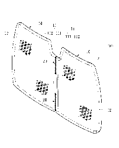
Disclosed is a folding sun-shading device, comprising two sun
shading plates and a bundling member. Each of the sun shading
plates comprises a ring frame, a shade curtain, a connecting
member, and a gap, wherein a frame edge where the two ring
frames get close to each other is defined as a joining frame edge,
and the part other than the joining frame edge is defined as an
operating frame edge. The bundling member penetrates each of
the gaps and is connected to each of the joining frame edges in a
bundling manner, and comprises a plurality of bending sections
provided on one side of each of the joining frame edges and a
plurality of limitation sections connected to each of the bending
sections and provided on the other side of each of the connection
frame edges.


French Abstract

La présente invention concerne un dispositif pare-soleil pliant (100), comprenant deux plaques pare-soleil (10) et un élément d'assemblage (20). Chacune des plaques pare-soleil (10) comprend un cadre annulaire (11), un rideau d'ombrage (12) entouré par le cadre annulaire, un élément de liaison (13) reliant le cadre annulaire (11) et le rideau d'ombrage (12) à des intervalles, et un espacement (14) disposé entre le cadre annulaire (11) et le rideau d'ombrage (12), un bord de cadre où les deux cadres annulaires (11) se rapprochent l'un de l'autre étant défini comme un bord de cadre de jonction (111) et la partie autre que le bord de cadre de jonction (111) étant définie comme un bord de cadre opérationnel (112). L'élément d'assemblage (20) pénètre chacun des espacements (14) et est relié à chacun des bords de cadre de jonction (111) dans un mode d'assemblage, et comprend une pluralité de sections pliables (21) disposées sur un côté de chacun des bords de cadre de jonction (111) et une pluralité de sections de limitation (22) reliées à chacune des sections pliables (21) disposées sur l'autre côté de chacun des bords de cadre de jonction (111); et l'élément d'assemblage (20) a un état déplié dans lequel chacune des sections pliables (21) est tendue de manière à limiter chacun des bords de cadre opérationnels (112) pour les séparer au maximum, et un état plié dans lequel chacune des sections de limitation (22) est tendue pour guider un des bords de cadre opérationnels (112) pour tourner autour d'un pivot et chevaucher l'autre bord de cadre opérationnel (112).

Claims

Note: Claims are shown in the official language in which they were submitted.


What is Claimed is:
1. A folding sun-shading device, comprising:
two sun shading plates each including an ring frame, a
shade curtain surrounded by the ring frame, a connecting
member connected the ring frame and the shade curtain in a
spaced manner and a gap interposed between the ring frame
and the shade curtain, the two ring frames including two
abutting sides defined respectively as a joining frame edge
and other portions outside the joining frame edge defined
respectively as an operating frame edge; and
a bundling member which binds the joining frame edge
through the gap and includes a plurality of bending sections at
the joining frame edge and a plurality of limitation sections
connected to the bending sections and located at another side
from the joining frame edge, the bundling member including
an extended state in which each bending section is tightly
stretched to confine each operating frame edge to be separated
from each other in a maximum manner, and a folding state in
which each limitation section is tightly stretched to allow one
operating frame edge to swivel and fold over another
operating frame edge.
2. The folding sun-shading device of claim 1, wherein the
limitation sections bind the joining frame edge at a range
greater than the range of the bending sections binding the
joining frame edge.

3. The folding sun-shading device of claim 2, wherein the
bending sections are plain stitching threads straddled the
joining frame edge, and the limitation sections are twilled
stitching threads straddled the joining frame edge in a
staggered manner.
4. The folding sun-shading device of claim 1, wherein the
bundling member includes a tail binding section at two sides
of the bending sections and the limitation sections to bind the
joining frame edges.
5. The folding sun-shading device of claim 1, wherein the
ring frame is flexible and the connecting member is a layer
covered by cloth.
6. The folding sun-shading device of claim 1, wherein the
ring frame is flexible and the connecting member is a mesh
structure.
7. The folding sun-shading device of claim 1, wherein each
sun shading plate includes at least one magnetic attraction
element located on the ring frame.
8. The folding sun-shading device of claim 1, wherein each
sun shading plate includes at least one suction cup located on
the shade curtain.
11

Description

Note: Descriptions are shown in the official language in which they were submitted.


CA 02993107 2018-01-19
FOLDING SUN-SHADING DEVICE
FIELD OF THE INVENTION
The present invention relates to a folding sun-shading
device and particularly to a folding sun-shading device with a
plurality of sun shading plates that are foldable for storing.
BACKGROUND OF THE INVENTION
When vehicles are parked outdoors for a prolonged period
and exposed to strong sunshine the temperature inside the
vehicles increases that makes drivers entering the vehicles feel
sweltering and uncomfortable. In addition, the interior seating
and draperies of the vehicles also are prone to degrading,
peeling or discoloring when exposed to the sunshine. To
remedy such problems various types of sunshades have been
developed to reduce damages caused by the strong sunshine.
A conventional vehicle sunshade includes a plurality of
indented folding traces formed by compression to facilitate
folding and save storing space. However, due to the folding
traces are uneven, gaps are easily formed between the
sunshade and vehicle window frames that result in passing
through of light, or not secure coupling between them that
could cause loosening off of the sunshade. To overcome those
problems another type of sunshade has been developed that
comprises a flexible metal frame which can be bent to fold the
entire sunshade into a lump to make storing easier, and also
can be extended to mate the contour of the vehicle window

CA 02993107 2018-01-19
frames to fully block sunshine. However, the windshield of
the vehicles usually is formed at a larger size, making the
flexible metal frame with desired evenness requires complex
fabrication processes that make manufacturing cost higher.
Moreover, fabricating the flexible metal frame for a larger
area also requires greater strength and needs bigger and
thicker metal frame materials, and also requires users to take
greater strength and effort to bend for storing. As a result, use
inconvenience increases. All this shows that there is still room
for improvement.
SUMMARY OF THE INVENTION
The primary object of the present invention is to solve the
problems of the conventional one-piece flexible sunshade of
higher fabrication cost and not easy bending for storing.
To achieve the foregoing object the present invention
provides a folding sun-shading device that comprises two sun
shading plates and a bundling member. Each sun shading plate
includes an ring frame, a shade curtain surrounded by the ring
frame, a connecting member connecting the ring frame and the
shade curtain in a spaced manner and a gap interposed
between the ring frame and the shade curtain. The two ring
frames include respectively one side abutting each other to be
defined as a joining frame edge and other portions outside the
joining frame edge defined as an operating frame edge. The
bundling member binds and connects each joining frame edge
2

CA 02993107 2018-01-19
through the gap, and includes a plurality of bending sections
located at one side of each joining frame edge and a plurality
of limitation sections located at another side from each joining
frame edge and connected to each bending section. The
bundling member also includes an extended state in which
each bending section is tightly stretched to confine each
operating frame edge to be separated from each other in a
maximum manner, and a folding state in which each limitation
section is tightly stretched to allow one operating frame edge
to swivel and fold over another operating frame edge.
In one aspect the limitation sections are bound to each
joining frame edge at a range greater than the range of the
bending sections bound to each joining frame edge.
In another aspect the bending sections are plain stitching
threads straddled each joining frame edge and the limitation
sections are twilled stitching threads straddled each joining
frame edge in a staggered manner.
In yet another aspect the bundling member includes a tail
binding section at two sides of the bending sections and the
limitation sections to bind each joining frame edge.
In yet another aspect the ring frame is flexible and the
connecting member is a layer covered by cloth.
In yet another aspect the ring frame is flexible and the
connecting member is a mesh structure.
In yet another aspect each sun shading plate includes at
3

CA 02993107 2018-01-19
least one magnetic attraction member located on the ring
frame.
In yet another aspect each sun shading plate includes at
least one suction cup located on the shade curtain.
The invention thus formed, compared with the
conventional techniques, can provide many advantages,
notably:
The folding sun-shading device of the invention can be
fabricated in two smaller sun shading plates that are coupled
through a turning and folding structure. Through the turning
and folding structure the sun shading plates can be overlapped
and bent under forces to facilitate storing. Hence it can be
made at a lower cost than the conventional techniques of
directly making the sunshade at a greater size. Usability
improves. It also can be snugly fitted to vehicle window
frames to enhance light blocking efficacy.
The foregoing, as well as additional objects, features and
advantages of the invention will be more readily apparent
from the following detailed description, which proceeds with
reference to the accompanying drawings.
BRIEF DESCRIPTION OF THE DRAWINGS
FIG. 1 is a perspective view of a first embodiment of the
invention.
FIG. 2 is a fragmentary sectional view of FIG. 1.
FIG. 3 is a perspective view of the first embodiment of the
4

,
CA 02993107 2018-01-19
invention seen from another side.
FIG. 4 is a fragmentary sectional view of FIG. 3.
FIG. 5 is a side view of a vehicle sun shading plate of the
invention in an extended state.
FIG. 6 is a schematic view of a vehicle sun shading plate of
the invention in a use condition.
FIG. 7 is a perspective view of a vehicle sun shading plate of
the invention in a folding condition.
FIG. 8 is a schematic view of a second embodiment of the
invention in a use condition.
DETAILED DESCRIPTION OF THE PREFERRED
EMBODIMENTS
Please referring to FIG. 1, the present invention aims to
provide a folding sun-shading device 100 that mainly
comprises at least two sun shading plates 10 and a bundling
member 20. The folding sun-shading device 100 is deployed
inside a vehicle to block sunshine from outside. The bundling
member 20 is connected to each sun shading plate 10 in a
bendable manner to facilitate storing of the folding
sun-shading device 100. In practice the invention also can be
used on other carriers such as buses, yachts or airplanes, or
even windows of buildings, without limited to vehicle
windows. The folding sun-shading device 100 also can include
more than two sets of the sun shading plates 10.
More specifically, please referring to FIGS. 1 and 2, each
5

CA 02993107 2018-01-19
sun shading plate 10 includes an ring frame 11, a shade
curtain 12 surrounded by the ring frame 11, a connecting
member 13 connecting the ring frame 11 and the shade curtain
12 in a spaced manner and a gap 14 interposed between the
ring frame 11 and the shade curtain 12. The two ring frames
11 include respectively one side abutting each other to be
defined as a joining frame edge 111 and other portions outside
the joining frame edge 111 defined as an operating frame edge
112. The "joining frame edge 111" means one side of each
ring frame 11 that is connected with each other, while the
"operating frame edge" 112 means another side to facilitate
grasping and force applying of users to make retraction for
storing or folding. In this embodiment the ring frame 11 is
flexible. The shade curtain 12 can be made of aluminum foiled
blister cloth, mesh, yarn screen or the like. It also can be
formed by coating reflective paint or the like on the shade
curtain 12. The connecting member 13 is made from material
with a definite stiffness such as a layer covered by cloth or a
mesh structure that can be deformed under forces so that when
the ring frame 11 is extended the connecting member 13 can
be propped up and the shade curtain 12 also can be stretched
to form a sheet with the gap 14 formed between the ring frame
11 and the shade curtain 12.
Please also referring to FIG. 1, FIG. 2, FIG. 3, and FIG. 4,
the bundling member 20 binds and connects each joining
6

= CA 02993107 2018-01-19
frame edge 111 through the gap 14, and includes a plurality of
bending sections 21 located at one side of each joining frame
edge 111 and a plurality of limitation sections 22 located at
another side of each joining frame edge 111 and connected to
the bending sections 21. Also referring to FIG. 5, the bundling
member 20 also includes an extended state in which each
bending section 21 is tightly stretched to confine each
operating frame edge 112 to be separated from each other in a
maximum manner, and a folding state in which each limitation
section 22 is tightly stretched to allow one operating frame
edge 112 to swivel and fold over another operating frame edge
112 as shown in FIGS. 6 and 7.
In a first embodiment of the invention the bending
sections 21 are plain stitching threads straddled each joining
frame edge 111, and the limitation sections 22 are twilled
stitching threads straddled each joining frame edge 111 in a
staggered manner. At the extended state because the limitation
sections 22 and the bending sections 21 at two sides of the
two joined sun shading plates 10 have different thread lengths,
the bending sections 21 with a smaller binding range cause the
strapped operating frame edge 112 unable to swivel away
from the bending sections 21 because of thread length
limitation. On the other hand, at the folding state, due to the
limitation sections 22 have a longer thread length the two sun
shading plates 10 can be swiveled and overlapped to retract
7

CA 02993107 2018-01-19
the bending sections 21 into the gap 14 of the connecting
member 13. In addition, the bundling member 20 further
includes a tail binding section 23 at two sides of the bending
sections 21 and the limitation sections 22 to bind each joining
frame edge. The tail binding section 23 can be a plurality of
plain stitching threads formed in a dense and continuous
manner formed between the joining frame edges 111 or thread
knots to avoid the threads from loosening off. However, the
aforesaid structures or techniques are not the limitation of the
invention.
Please referring to FIG. 8, in another embodiment of the
invention each ring frame 11 includes at least one magnetic
attraction element 15 located on the ring frame 11, or a
suction cup 16 located on the shade curtain 12 to attach to a
vehicle window frame 500 or a vehicle window or the like, so
that each shade curtain 12 can securely cover the vehicle
window to block sunshine as desired. The magnetic attraction
element 15 or the suction cup 16 is merely one of possible
embodiments. In practice they can be changed or switched
according to actual requirements.
As a conclusion, the folding sun-shading device of the
invention consists of the sun shading plates and the bundling
member that can be made at a lower cost than the
conventional flexible sun shading plate formed at a larger size.
It also makes storing easier than the conventional flexible sun
8

= CA 02993107 2018-01-19
shading plate of a larger size that requires greater structural
strength.
9

Representative Drawing
A single figure which represents the drawing illustrating the invention.
Administrative Status

2024-08-01:As part of the Next Generation Patents (NGP) transition, the Canadian Patents Database (CPD) now contains a more detailed Event History, which replicates the Event Log of our new back-office solution.

Please note that "Inactive:" events refers to events no longer in use in our new back-office solution.

For a clearer understanding of the status of the application/patent presented on this page, the site Disclaimer , as well as the definitions for Patent , Event History , Maintenance Fee  and Payment History  should be consulted.

Event History

Description Date
Common Representative Appointed 2020-11-07
Grant by Issuance 2019-11-26
Inactive: Cover page published 2019-11-25
Common Representative Appointed 2019-10-30
Inactive: Final fee received 2019-09-30
Pre-grant 2019-09-30
Notice of Allowance is Issued 2019-08-27
Letter Sent 2019-08-27
Notice of Allowance is Issued 2019-08-27
Inactive: Approved for allowance (AFA) 2019-07-30
Inactive: Q2 passed 2019-07-30
Amendment Received - Voluntary Amendment 2019-04-10
Inactive: S.30(2) Rules - Examiner requisition 2018-11-15
Inactive: Report - No QC 2018-11-10
Change of Address or Method of Correspondence Request Received 2018-06-11
Inactive: Cover page published 2018-03-21
Inactive: Acknowledgment of national entry - RFE 2018-02-07
Inactive: First IPC assigned 2018-02-02
Letter Sent 2018-02-02
Inactive: IPC assigned 2018-02-02
Application Received - PCT 2018-02-02
National Entry Requirements Determined Compliant 2018-01-19
Request for Examination Requirements Determined Compliant 2018-01-19
All Requirements for Examination Determined Compliant 2018-01-19
Application Published (Open to Public Inspection) 2017-05-04

Abandonment History

There is no abandonment history.

Maintenance Fee

The last payment was received on 2019-09-12

Note : If the full payment has not been received on or before the date indicated, a further fee may be required which may be one of the following

  • the reinstatement fee;
  • the late payment fee; or
  • additional fee to reverse deemed expiry.

Patent fees are adjusted on the 1st of January every year. The amounts above are the current amounts if received by December 31 of the current year.
Please refer to the CIPO Patent Fees web page to see all current fee amounts.

Fee History

Fee Type Anniversary Year Due Date Paid Date
MF (application, 2nd anniv.) - standard 02 2017-10-26 2018-01-19
Basic national fee - standard 2018-01-19
Request for examination - standard 2018-01-19
MF (application, 3rd anniv.) - standard 03 2018-10-26 2018-08-28
MF (application, 4th anniv.) - standard 04 2019-10-28 2019-09-12
Final fee - standard 2019-09-30
MF (patent, 5th anniv.) - standard 2020-10-26 2020-09-10
MF (patent, 6th anniv.) - standard 2021-10-26 2021-07-13
MF (patent, 7th anniv.) - standard 2022-10-26 2022-06-27
MF (patent, 8th anniv.) - standard 2023-10-26 2023-07-17
Owners on Record

Note: Records showing the ownership history in alphabetical order.

Current Owners on Record
SHYU FUU INDUSTRIAL CO., LTD.
Past Owners on Record
JING-SHYONG GONG
Past Owners that do not appear in the "Owners on Record" listing will appear in other documentation within the application.
Documents

To view selected files, please enter reCAPTCHA code :


To view images, click a link in the Document Description column. To download the documents, select one or more checkboxes in the first column and then click the "Download Selected in PDF format (Zip Archive)" or the "Download Selected as Single PDF" button.

List of published and non-published patent-specific documents on the CPD .

If you have any difficulty accessing content, you can call the Client Service Centre at 1-866-997-1936 or send them an e-mail at CIPO Client Service Centre.


Document
Description 
Date
(yyyy-mm-dd) 
Number of pages   Size of Image (KB) 
Abstract 2018-01-18 1 34
Description 2018-01-18 9 297
Claims 2018-01-18 2 63
Drawings 2018-01-18 8 104
Representative drawing 2018-03-20 1 15
Abstract 2019-04-09 1 23
Representative drawing 2019-11-17 1 13
Acknowledgement of Request for Examination 2018-02-01 1 187
Notice of National Entry 2018-02-06 1 231
Commissioner's Notice - Application Found Allowable 2019-08-26 1 163
Maintenance fee payment 2023-07-16 1 25
Examiner Requisition 2018-11-14 3 136
National entry request 2018-01-18 3 76
Patent cooperation treaty (PCT) 2018-01-18 1 44
Patent cooperation treaty (PCT) 2018-01-18 2 77
International search report 2018-01-18 4 134
Amendment - Abstract 2018-01-18 2 107
Amendment / response to report 2019-04-09 3 77
Final fee 2019-09-29 2 48