Note: Descriptions are shown in the official language in which they were submitted.
FOOTWEAR HAVING A SOLE WITH A PLURALITY OF CHAMBERS
Field
Embodiments of the present disclosure relate to footwear and more particularly
to a sole for footwear or footwear having a sole.
Introduction
Work boots, athletic footwear, and other types of footwear may have
components that are designed to provide for cushioning, shock absorption, and
traction. Footwear typically includes a sole having at least a midsole and an
outsole.
The midsole is generally constructed of materials to provide for cushioning
and shock
absorption, while the outsole is generally constructed of materials to provide
for
traction with a support surface.
Summary
Disclosed herein are examples of footwear and soles for footwear.
In one example, soles for footwear are disclosed. The sole may include a
midsole having a first surface. The sole may additionally include an outsole
having a
second surface and a plurality of first recesses. The second surface may be
attached
= 20 to the first surface. The first surface and the plurality of
first recesses may define a
plurality of chambers. One or more chambers of the plurality of chambers may
include
trapped air. The midsole may further include first protruding portions that
extend
downwardly from the first surface toward one or more first recesses of the
plurality of
first recesses.
In another example, footwear are disclosed. The footwear may include an upper
for receiving a foot of a user. The footwear may additionally include a sole
having a
midsole and an outsole. The midsole may include a first surface. The outsole
may
include a second surface and a plurality of first recesses. The second surface
may be
attached to the first surface. The first surface and the plurality of first
recesses may
define a plurality of chambers. One or more chambers of the plurality of
chambers may
include trapped air. The midsole may further include first protruding portions
that
1
CA 2993544 2020-03-30
extend downwardly from the first surface toward one or more first recesses of
the
plurality of first recesses.
In accordance with an embodiment, there is provided a sole for footwear
including a midsole having a first surface and an outsole having a second
surface and
a plurality of first recesses, the second surface is attached to the first
surface, the first
surface and the plurality of first recesses define a plurality of chambers,
one or more
chambers of the plurality of chambers includes trapped air, the midsole
further
includes first protruding portions that extend downwardly from the first
surface toward
one or more first recesses of the plurality of first recesses, wherein the
sole does not
include one or more passages that fluidly connect two or more chambers of the
plurality of chambers, wherein each of the plurality of first recesses
includes a bottom
and a plurality of sidewalls, each of the plurality of first recesses includes
inclined
surfaces disposed between the plurality of sidewalls and the second surface,
the first
surface includes second protruding portions configured to be received on and
contact
the inclined surfaces of two or more recesses of the plurality of first
recesses.
In accordance with another embodiment, there is provided footwear including
an upper for receiving a foot of a user and a sole having a midsole and an
outsole, the
midsole has a first surface, the outsole has a second surface and a plurality
of first
recesses, the second surface is attached to the first surface, the first
surface and the
plurality of first recesses define a plurality of chambers, one or more
chambers of the
plurality of chambers includes trapped air, the midsole further includes first
protruding
portions that extend downwardly from the first surface toward one or more
first
recesses of the plurality of first recesses, wherein the sole does not include
one or
more passages that fluidly connect two or more chambers of the'plurality of
chambers,
wherein each of the plurality of first recesses includes a bottom and a
plurality of
sidewalls, each of the plurality of first recesses includes inclined surfaces
disposed
between the plurality of sidewalls and the second surface, the first surface
includes
second protruding portions configured to be received on and contact the
inclined
surfaces of two or more recesses of the plurality of first recesses.
Features, functions, and advantages may be achieved independently in various
embodiments of the present disclosure, or may be combined in yet other
la
CA 2993544 2020-03-30
CA 02993544 2018-01-24
WO 2017/019462 PCT/US2016/043426
embodiments, further details of which can be seen with reference to the
following
description and drawings.
Brief Description of the Drawings
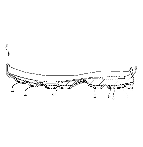
Fig. 1 is a side view of an example of footwear of the present disclosure
having a plurality of chambers.
Fig. 2 is a bottom view of the footwear of Fig. 1.
Fig. 3 is an exploded view of the footwear of Fig. 1, showing a shoe upper, a
midsole, and an outsole.
Fig. 4 is a top view of the outsole of Fig. 3.
Fig. 5 is a bottom view of the midsole of Fig. 3.
Fig. 6 is a bottom view of the footwear of Fig. 1, showing projections of the
midsole received in recesses of the outsole.
Fig. 7 is a partial sectional view of the sole of the footwear of Fig. 1 taken
along lines 7-7 in Fig. 2.
Fig. 8 is a partial sectional view of the sole of the footwear of Fig. 1 taken
along lines 8-8 in Fig. 2.
Figs. 9-11 are bottom views of other examples of the sole of the footwear of
Fig. 1.
Fig. 12 is a side view of another example of footwear of the present
disclosure.
Fig. 13 is a bottom view of the footwear of Fig. 12, showing projections of
the
midsole received in recesses of the outsole.
Fig. 14 is a side view of a further example of footwear of the present
disclosure.
Fig. 15 is a bottom view of the footwear of Fig. 14, showing projections of
the
midsole received in recesses of the outsole.
Fig. 16 is a side view of another example of footwear of the present
disclosure.
Fig. 17 is a bottom view of the footwear of Fig. 16, showing projections of
the
midsole received in recesses of the outsole.
Fig. 18 is a bottom view of another example of the footwear of Fig. 16.
2
CA 02993544 2018-01-24
WO 2017/019462 PCT/US2016/043426
Fig. 19 is a bottom view of a further example of the footwear of Fig. 16.
Fig. 20 is an isometric view of an example of two recesses of an outsole
connected by a passage.
Fig. 21 is an isometric view of an example of a recess having an insert.
Detailed Description of the Disclosure
Overview
Various embodiments of footwear having a sole with a plurality of chambers
are described below and illustrated in the associated drawings. Unless
otherwise
specified, an embodiment and/or its various components may contain at least
one of
the structure, components, functionality, and/or variations described and/or
illustrated herein. Furthermore, the structures, components, functionalities,
and/or
variations described and/or illustrated herein in connection with the present
teachings may be included in other embodiments. The following description of
various embodiments is merely illustrative in nature and is in no way intended
to limit
the disclosure, us application, or uses. Additionally, the advantages provided
by the
embodiments, as described below, are illustrative in nature and not all
embodiments
provide the same advantages or the same degree of advantages.
Disclosed herein are footwear haying a sole with a plurality of chambers. In
some embodiments, the midsole and the outsole may form a plurality of
chambers.
In some embodiments, one or more of the chambers may include trapped air.
Alternatively, or additionally, one or more of the chambers may include gel,
foam,
insert(s), drop-in(s), and/or other materials.
Examples, Components, and Alternatives
The following examples describe selected aspects of illustrative embodiments
as well as related systems and/or methods. These examples are intended for
illustration and should not be interpreted as limiting the entire scope of the
present
disclosure. Each example may include one or more distinct inventions, and/or
contextual or related information, function, and/or structure.
3
CA 02993544 2018-01-24
WO 2017/019462 PCT/US2016/043426
Example 1:
Figs. 1-8 show an example of footwear 30 of the present disclosure. The
footwear may include an upper 32 and a sole 34 attached to the upper. Upper 32
may cover any suitable portion of a user's foot. For example, the upper in
Fig. 1 has
a high cut (or high top) that is designed to extend above a user's ankle bone.
Although upper 32 is shown as having a high cut, upper 32 may have a low cut
(or
low top) that does not extend above a user's ankle bone or may have any
suitable
cut that covers any suitable portion of a user's foot.
Sole 34 may include any suitable layers, such as an outsole (or outer sole
layer) 36 and a midsole (or midsole layer) 38. Outsole 36 and/or midsole 38
may
include any suitable material(s), such as rubber, ethylene-vinyl acetate
(EVA),
thermoplastic polyurethane (TPU), and/or other materials.
Outsole 36 may extend at least substantially the entire length of the
footwear.
Although the footwear of Figs. 1-18 includes an outsole that wraps around at
least a
portion of the toe of the footwear, the footwear of the present disclosure may
include
any suitable oulsole. in some examples, the lootwear may include an oulsole 36
that
does not wrap around the toe and/or may wrap around at least a portion of the
heel
of the footwear.
Outsole 36 may include a forefoot portion 42, a midfoot portion 44, and a heel
portion 46. Additionally, the outsole may have an upper surface 48 and a lower
surface 50. The upper surface may include a base surface or base 51 and a
plurality
of depressions or recesses 52. Lower surface 50 may include one or more
projections 54, which may be formed from recesses 52 of the upper surface. One
or
more of the projections may be configured to contact a support surface. Lower
surface 50 may include one or more projections 54 that are not formed by
recesses
52 on upper surface 48, such as the U-shaped projections on the forefoot and
heel
portions of lower surface 50 that are not formed by recesses 52 on upper
surface 48.
Recesses 52 may be distributed along upper surface 48 in any suitable
configuration and/or layout. For example, upper surface 48 may include
transverse
end portions 56, 58 and a central portion 60 disposed between the transverse
end
portions. One or more of transverse end portions 56, 58 and/or central portion
60
may include one or more recesses 52. In some embodiments, each of the
transverse
4
CA 02993544 2018-01-24
WO 2017/019462 PCT/US2016/043426
end portions and/or central portion may include one or more recesses 52.
Although
upper surface 48 is shown to include recesses 52 in each of the transverse end
portions and central portion, the upper surface may include recesses 52 in
only one
or both of the transverse end portions, in only the central portion, and/or
any suitable
combination. In some embodiments, upper surface 48 may include recesses 52 in
only forefoot portion 42, in only midfoot portion 44, in only heel portion 46,
in only the
forefoot and heel portions, in only the forefoot and midfoot portions, or in
only the
midfoot and heel portions. Other combinations of the above configurations are
included in the present disclosure, such as recesses 52 in only both
transverse end
portions and in only the forefoot and/or heel portions, etc.
Each portion of upper surface 48 may include any suitable number of
recesses 52. For example, one or both transverse end portions 56, 58 and/or
central
portion 60 may each include one, two, three, four, five, six, seven, eight,
nine or
more recesses 52. Additionally, or alternatively, the forefoot, midfoot,
and/or heel
portion(s) may each include one, two, three, four, five, six, seven, eight,
nine or more
feCUSSUS 52.
Recesses 52 may include any suitable structure. For example, one or more
recesses 52 may include a bottom surface 62 and a plurality of sidewalls 64.
The
recesses may have any suitable shape(s). For example, one or more recesses 52
may be triangular-shaped and have only three sidewalls 64. Additionally, or
alternatively, one or more recesses 52 may be square-shaped or rectangular-
shaped
and have only four sidewalls 64. Recesses 52 may be shaped in other suitable
ways,
such as circular-shaped, U-shaped, V-shaped, etc. Sidewalls 64 may include any
suitable shape(s). For example, one or more sidewalls 64 may be concave-
shaped,
such as to correspond to one or more projections from the midsole that include
convex-shaped wall(s) as discussed further below.
In some embodiments, recesses 52 may include one or more inclined
surfaces 66 disposed between base 51 and sidewalls 64. Inclined surfaces 66
may,
for example, provide a perimeter 68 around the sidewalls and/or the bottom
surface.
The inclined surfaces may have any suitable shape(s). For example, one or more
inclined surfaces 66 may be concave-shaped, such as to correspond to one or
more
5
CA 02993544 2018-01-24
WO 2017/019462 PCT/US2016/043426
protruding portions of the midsole that are convex-shaped, as further
discussed
below.
As shown in Fig. 5, midsole 38 may include a forefoot portion 70, a midfoot
portion 72, and a heel portion 74. Additionally, the midsole may have an upper
surface 76 and a lower surface 78. Lower surface 78 may include a base surface
or
base 80 that is attached to base 51 of outsole 36. When attached, base 80 and
recesses 52 may define a plurality of compartments or chambers 82 having
trapped
air and/or other materials, such as shown in Fig. 6. During the manufacturing
process, attaching the midsole and the outsole may trap ambient air in the
chamber(s). When chambers 82 include trapped air, those chambers may
sometimes be referred to as "air chambers," "ambient air chambers," "air
pods," or
"air pockets." Alternatively, or additionally, one or more chambers 82 may
include
gel, foam, and/or other materials, such as insert(s) or drop-in(s) sized to be
received
in the recess(es) and/or chamber(s). The insert(s) or drop-in(s) may be made
of any
suitable material(s) and/or may provide for one or more functions. For
example, the
insert may be made of polyurethane and/or provide br increased shock
absorption.
Sole 34 may include any suitable combination of air chambers, chambers with
gel,
chambers with foam, chambers with inserts, and/or chambers with other
materials
depending on the shock absorption, traction, cushioning, and/or other
characteristics
desired.
Lower surface 78 of midsole 38 may include a plurality of first protruding
portions 84 that are configured to extend downwardly from base 80 toward one
or
more recesses 52 of the outsole. In some embodiments, one or more first
protruding
portions 84 may contact bottom surface 62 of one or more recesses 52. The
first
protruding portions may be contained within one or more chambers 82. First
protruding portions 84 may have any suitable size(s) configured to be received
in
recesses 52 and/or chambers 82. For example, first protruding portions 84 may
occupy any suitable portion(s) of chambers 82, such as about 30% to about 50%,
as
shown in Fig. 6.
The first protruding portions may be distributed along lower surface 78 in any
suitable configuration and/or layout to correspond one or more recesses 52.
For
example, lower surface 78 may include transverse end portions 86, 88 and a
central
6
CA 02993544 2018-01-24
WO 2017/019462 PCT/US2016/043426
portion 90. In some embodiments, lower surface 78 may include first protruding
portions 84 in only transverse end portions 86, 88. Alternatively, that
surface may
include the first protruding portions in only one of the transverse end
portions, in only
the central portion, and/or any suitable combination. In some embodiments,
lower
surface 78 may include first protruding portions in only forefoot portion 70,
in only
midfoot portion 72, in only heel portion 74, in only the forefoot and heel
portions, in
only the forefoot and midfoot portions, or in only the midfoot and heel
portions. Other
combinations of the above configurations are included in the present
disclosure,
such as first protruding portions 84 in only one transverse end portion and in
only the
forefoot and/or heel portions, etc.
Each portion of lower surface 78 may include any suitable number of first
protruding portions 84. For example, one or both transverse end portions 86,
88
and/or central portion 90 may each include one, two, three, four, five, six,
seven,
eight, nine or more first protruding portions 84. Additionally, or
alternatively, the
forefoot, midfoot, and/or heel portion(s) may each include one, two, three,
four, five,
six, seven, eight, nine or more first protruding poi lions 84.
First protruding portions 84 may include any suitable structure. For example,
one or more first protruding portions 84 may include a top surface 92 and a
plurality
of sidewalls 94. The first protruding portions may have any suitable shape(s).
For
example, one or more first protruding portions 84 may be square-shaped or
rectangular-shaped and have only four sidewalls 94. Recesses 52 may be shaped
in
other suitable ways, such as triangular-shaped, circular-shaped, U-shaped, V-
shaped, etc. Sidewalls 94 may include any suitable shape(s). For example, one
or
more sidewalls 94 may be shaped to correspond to the shape of one or more
adjacent sidewalls 64 of recesses 52 such that one or more sidewalls 94 are in
contact with at least a portion of one or more sidewalls 64, as shown in Fig.
7. In
some embodiments, one or more sidewalls 94 of first protruding portions 84 may
be
convex-shaped to correspond to one or more concave-shaped sidewalls 64 of
recesses 52. In some embodiments, entire sidewall(s) 94 may be in contact with
entire sidewall(s) 64.
In some embodiments, lower surface 78 of midsole 38 may include one or
more second protruding portions 96 configured to be received in recesses 52 of
7
CA 02993544 2018-01-24
WO 2017/019462 PCT/US2016/043426
outsole 36. In some embodiments, second protruding portions 96 may extend
downwardly from base 80 substantially less than first protruding portions 84.
Second
protruding portions 96 may include a perimeter 98 and may be any suitable
shape(s)
to correspond to the shape(s) of the recesses. When recesses 52 include
inclined
surfaces 66, perimeter 98 of second protruding portions 96 may be configured
to be
received on and contact inclined surfaces 66. For example, when inclined
surfaces
66 are concave-shaped, second protruding portions 96 may include a convex-
shaped perimeter 98.
Lower surface 78 may include any suitable second protruding portions 96 for
all recesses 52 or for less than all of the recesses. For example, lower
surface 78
may include second protruding portions 96 in only one or both of the
transverse end
portions, in only the central portion, and/or any suitable combination. In
some
embodiments, lower surface 78 may include second protruding portions 96 in
only
forefoot portion 70, in only midfoot portion 72, in only heel portion 74, in
only the
forefoot and heel portions, in only the forefoot and midfoot portions, or in
only the
midfool and heel porlions. Olher combinalions of the above configuralions are
included in the present disclosure, such as second protruding portions 96 in
only one
transverse end portion and in only the forefoot and/or heel portions, etc.
In some embodiments, sole 34 may include an interface or gasket layer 100,
.. as shown in Figs. 3 and 7-8. The gasket layer may be disposed between the
midsole
and the outsole, such as between upper surface 48 and lower surface 78.
Additionally, gasket layer 100 may be configured to seal the trapped air in
chambers
82. The gasket layer may be made of any suitable material(s). In some
embodiments, midsole 38 (such as lower surface 78) may include a channel 102
sized to receive the gasket layer.
Examples 2-4:
Figs. 9-11 show embodiments of sole 34, similar to those described above,
but with two or more chambers 82 being in fluid communication with each other.
For
example, an upper surface of outsole 36 may include one or more connector
recesses 104 such that, when the midsole and outsole are attached, a lower
surface
of the midsole and connector recesses 104 define one or more passages 106 that
8
CA 02993544 2018-01-24
WO 2017/019462 PCT/US2016/043426
fluidly connect two or more chambers. In other words, the passages allow two
or
more chambers to share the trapped air and/or other fluids in the chambers.
Fig. 9 shows four chambers 82 in forefoot portion 70 fluidly connected to each
other and five chambers 82 in heel portion 74 fluidly connected to each other.
Fig. 10
shows three pairs of fluidly connected chambers 82 in central portion 60. Fig.
11
shows six chambers 82 in forefoot portion 70, two chambers 82 in midfoot
portion 72
fluidly connected to each other, and six chambers 82 in heel portion 74
fluidly
connected to each other. Other variations of fluidly connected chambers are
included
in the present disclosure.
Examples 5-7:
Figs. 12-19 show different embodiments of footwear 30, which is generally
indicated at 110. Footwear 110 may include a shoe upper 112 and a sole 114
attached to the upper. Upper 112 may cover any suitable portion of a user's
foot. For
example, the uppers in Fig. 12-17 are low cut (or low top) uppers that do not
extend
above a user's ankle bone.
Sole 114 may include any suitable layers, such as an outsole (or outer sole
layer) 116 and a midsole (or midsole layer) 118. Outsole 116 and/or midsole
118
may include any suitable material(s), such as rubber, ethylene-vinyl acetate
(EVA),
thermoplastic polyurethane (TPU), and/or other materials.
Outsole 116 may include a forefoot portion 120, a midfoot portion 121, and a
heel portion 122. In some embodiments, outsole 116 may exclude one or more
portions, such as midfoot portion 121. For example, forefoot portion 120 and
heel
portion 122 may define an aperture or cavity 124 therebetween (such as where
at
least a portion of midfoot portion 121 would have been), as shown in Fig. 13.
When
outsole 116 excludes or does not include one or more portions, the outsole may
be
sometimes referred as "segmented outsole" 116. Alternatively, or additionally,
outsole 116 may include one or more cavities in the forefoot, midfoot, and/or
heel
portions. For example, outsole 116 in Fig. 17 includes cavities 124 in
forefoot portion
120.
The outsole may have an upper surface 126 and a lower surface 128. The
upper surface may include a plurality of depressions or recesses 130. Lower
surface
9
CA 02993544 2018-01-24
WO 2017/019462 PCT/US2016/043426
128 may include one or more projections 132, which may be formed from recesses
130 of the upper surface. Lower surface 128 may include one or more
projections
132 that are not formed by recesses 130 on upper surface 126 and/or extend
outward from lower surface 128, such as indicated at 133 in Figs. 13 and 17.
Those
projections may sometimes be referred to as "non-chamber projections." Non-
chamber projections 133 may be made of any suitable material(s), such as solid
rubber.
Recesses 130 may be distributed along upper surface 126 in any suitable
configuration and/or layout. For example, upper surface 126 may include
transverse
end portions 134, 135 and a central portion 136 disposed between the
transverse
end portions or extend from one transverse end portion to the other transverse
end
portion. One or more recesses 130 may extend between transverse end portions
134, 135. Alternatively, or additionally, one or more recesses 130 may extend
from
one of the transverse end portions to the other of the transverse end
portions, and
back to the initial transverse end portion, such as shown in Fig. 13. In some
embodimenls, upper surface 126 may include -------------------------------
iecesses 130 in only forefool ponion
120, in only midfoot portion 121, in only heel portion 122, in only the
forefoot and
heel portions, in only the forefoot and midfoot portions, or in only the
midfoot and
heel portions. Other combinations of the above configurations are included in
the
present disclosure.
Each portion of upper surface 126 may include any suitable number of
recesses 130. For example, the forefoot, midfoot, and/or heel portion(s) may
each
include one, two, three, four, five, six or more recesses 130. Recesses 130
(and the
corresponding projections 132) may be shaped in any suitable way(s), such as
elongate, circular-shaped, kidney-shaped, ring-shaped, triangular-shaped, U-
shaped, V-shaped, other shape(s), and any suitable combination of shapes. For
example, Fig. 13 shows recesses 130 that are elongate and/or ring-shaped or
circular-shaped. Additionally, Fig. 15 shows recesses 130 that are kidney-
shaped,
while Fig. 17 shows recesses 130 that are triangular-shaped. Non-chamber
projections 133 may be shaped in any suitable way(s), such as elongate,
circular-
shaped, kidney-shaped, ring-shaped, triangular-shaped, U-shaped, V-shaped,
other
shape(s), and any suitable combination of shapes. For example, Fig. 13 shows a
CA 02993544 2018-01-24
WO 2017/019462 PCT/US2016/043426
non-chamber projection 133 that is elongate and/or half-moon shaped.
Additionally,
Figs. 17-18 show non-chamber projections 133 that are U-shaped and triangular-
shaped, respectively.
Midsole 118 may include a forefoot portion 138, a midfoot portion 140, and a
heel portion 142. Additionally, the midsole may have an upper surface 144 and
a
lower surface 146. When attached, lower surface 146 and recesses 130 may
define
a plurality of chambers 148 having trapped air and/or other materials.
Alternatively,
or additionally, one or more chambers 148 may include gel, foam, and/or other
materials. In some embodiments, one or more chambers 148 may include insert(s)
or drop-in(s) 149 configured to be received in the recess(es) and/or
chamber(s), as
shown in Figs. 19 and 21. Inserts 149 may provide, for example, for increased
shock
absorption and/or decreased pronation.
Sole 114 may include any suitable combination of air chambers, chambers
with gel, chambers with foam, chambers with inserts, chambers with other
materials,
non-chamber projections, etc. depending on the shock absorption, traction,
cushioning, and/or oilier characierislics desired. For example, Fig. 17 shows
a
plurality of chambers 148 having trapped air, gel, and/or foam. Additionally,
Fig. 18
shows some of the chambers of Fig. 17 replaced with non-chamber projections
133
(which may be made, for example, from solid rubber). Moreover, Fig. 19 shows
some of the chambers of Fig. 17 with inserts 149. The sole of Fig. 18 may
provide,
for example, increased abrasion resistance and may prevent or minimize
pronation
compared to the sole of Fig. 17. The sole of Fig. 19 may provide, for example,
increased shock absorption compared to the sole of Fig. 17.
When outsole 116 includes one or more cavities 124, one or more extended
portions 150 of midsole 118 may extend through and/or occupy those cavities.
For
example, when outsole 116 is segmented, portion(s) 150 of midsole 118 may
extend
through cavity 124, as shown in Fig. 13. When outsole 116 includes two or more
cavities 124, two or more portions 150 of the midsole may extend through those
cavities, such as shown in Figs. 17-19. Extended portions 150 may include one
or
more projections 151, which may be shaped similar to and/or different from one
or
more projections 132. Projections 151 may be configured, for example, to
contact a
support surface when footwear 110 is in use. When a portion of midsole 118 is
11
CA 02993544 2018-01-24
WO 2017/019462 PCT/US2016/043426
exposed and/or extends through a cavity in outsole 116, the midsole may be
referred
to as "exposed midsole" 118. Although sole 114 is shown to include cavity 124
between the forefoot and heel portions of the outsole in Fig. 13 and cavities
124 in
the forefoot and heel portions of the outsole in Figs. 17-19, sole 114 may
alternatively, or additionally, include one or more cavities in any suitable
portion(s) of
the outsole, such as in the forefoot, midfoot, and/or heel portions. In those
embodiments, midsole 118 may include one or more portions 150 that extend
through the cavity(ies), and/or may include one or more projections 151.
Lower surface 146 of the midsole may include a plurality of protruding
portions 152 that are configured to extend downwardly from lower surface 146
toward one or more recesses 130 of the outsole. The protruding portions may be
contained within one or more chambers 148. Protruding portions 152 may have
any
suitable size(s) configured to be received in recesses 130 and/or chambers
148. For
example, protruding portions 152 may occupy any suitable portion(s) of
chambers
148.
The protruding portions may be distributed along lower surface 146 in any
suitable configuration and/or layout to correspond to one or more recesses
130. For
example, lower surface 146 may include transverse end portions 154, 156 and a
central portion 158. In some embodiments, lower surface 146 may include
protruding
portions 152 in only transverse end portions 154, 156. Alternatively, that
surface may
include the protruding portions in only one or both of the transverse end
portions, in
only the central portion, and/or any suitable combination. In some
embodiments,
lower surface 146 may include protruding portions in only forefoot portion
138, in
only midfoot portion 140, in only heel portion 142, in only the forefoot and
heel
.. portions, in only the midfoot and heel portions, or in only the forefoot
and midfoot
portions. Other combinations of the above configurations are included in the
present
disclosure.
Each portion of lower surface 146 may include any suitable number of
protruding portions 152. For example, one or both transverse end portions 154,
156
and/or central portion 158 may each include one, two, three, four, five, six,
seven,
eight, nine or more protruding portions 152. Additionally, or alternatively,
the forefoot,
midfoot, and/or heel portion(s) may each include one, two, three, four, five,
six,
12
CA 02993544 2018-01-24
WO 2017/019462 PCT/US2016/043426
seven, eight, nine or more protruding portions 152. Protruding portions 152
may
include at least one sidewall 160 that corresponds in shape to at least one
sidewall
162 of recesses 130 such that, for example, the sidewalls are in contact with
each
other.
Lower surface 146 may include any suitable protruding portions 152 for all
recesses 130 or for less than all of the recesses. For example, lower surface
146
may include protruding portions 152 in only one or both of the transverse end
portions, in only the central portion, and/or any suitable combination. In
some
embodiments, lower surface 146 may include protruding portions 152 in only the
forefoot portion, in only the midfoot portion, in only the heel portion, in
only the
forefoot and heel portions, in only the forefoot and midfoot portions, or in
only the
midfoot and heel portions. For example, Fig. 13 shows protruding portions 152
in
only the transverse end portions and in only the forefoot and heel portions.
Additionally, Fig. 15 shows protruding portions 152 throughout the sole of the
shoe.
Moreover, Figs. 17-19 show protruding portions in only one or both of the
transverse
end portions and in only the heel portion. Oilier combinations of the above
configurations are included in the present disclosure, such as protruding
portions in
only one transverse end portion and in only the forefoot and/or heel portions,
etc.
In some embodiments, two or more chambers 148 may be in fluid
communication with each other, as shown in Fig. 20. For example, upper surface
126 of outsole 116 may include one or more connector recesses 164 such that,
when the midsole and outsole are attached, lower surface 146 and connector
recesses 164 define one or more passages 166 that fluidly connect two or more
chambers. In other words, the passages allow two or more chambers to share the
trapped air, gel, and/or other fluid(s) in the chambers. For example, Figs. 17-
19 show
chambers 148 that are fluidly connected to each other via connector recesses
164.
Example 8:
This section describes additional aspects and features of embodiments
presented without limitation as a series of paragraphs, some or all of which
may be
alphanumerically designated for clarity and efficiency. Each of these
paragraphs can
be combined with one or more other paragraphs, and/or with disclosure from
13
CA 02993544 2018-01-24
WO 2017/019462 PCT/US2016/043426
elsewhere in this application, in any suitable manner. Some of the paragraphs
below
expressly refer to and further limit other paragraphs, providing, without
limitation,
examples of some of the suitable combinations.
AO. A sole for footwear, the sole comprising:
a midsole having a first surface; and
an outsole having a second surface and a plurality of first recesses, the
second surface is attached to the first surface, the first surface of the
midsole and
the plurality of first recesses define a plurality of chambers having trapped
air, the
midsole further includes first protruding portions that extend downwardly from
the
first surface toward one or more first recesses of the plurality of first
recesses.
Al. The sole of paragraph AO, wherein the first protruding portions
include
one or more walls that are shaped to correspond to part of the one or more
first
recesses such that the one or more walls are in contact with the part of those
recesses.
A2. The sole of paragraph Al, wherein the plurality of first recesses
includes a plurality of euncave-shaped walls, and the one or more walls are
convex-
shaped to correspond to the plurality of concave-shaped walls such that the
convex-
shaped walls are in contact with at least a portion of the concave-shaped
walls.
A3. The sole of any of paragraphs AO-A2, wherein the first protruding
portions extend downwardly to contact a bottom surface of the one or more
first
recesses.
A4. The sole of any of paragraphs AO-A3, wherein the plurality of first
recesses includes a bottom and a plurality of sidewalls.
AS. The sole of paragraph A4, wherein the plurality of first
recesses
includes inclined surfaces disposed between the plurality of sidewalls and the
second surface.
A6. The sole of paragraph A5, wherein the first surface includes second
protruding portions configured to be received on and contact the inclined
surfaces of
two or more first recesses of the plurality of first recesses.
A7. The sole of paragraph A6, wherein the second protruding portions
include a convex-shaped perimeter, and the inclined surfaces are concave-
shaped
to correspond to the convex-shaped perimeter.
14
CA 02993544 2018-01-24
WO 2017/019462 PCT/US2016/043426
A8. The sole of paragraph A4, wherein one or more first recesses of the
plurality of first recesses include a bottom and only three sidewalls.
A9. The sole of paragraph A4, wherein one or more first recesses of the
plurality of first recesses include a bottom and only four sidewalls.
A10. The sole of any of paragraphs AO-A9, wherein the outsole includes
transverse end portions and a central portion disposed between the transverse
end
portions, and the plurality of first recesses are distributed on the outsole
such that
each of the transverse end portions and the central portion includes two or
more first
recesses.
A11. The sole of paragraph Al 0, wherein the first protruding portions extend
downwardly toward the two or more recesses in only the transverse end
portions.
Al2. The sole of any of paragraphs AO-Al 1 , further comprising a gasket
layer disposed between the first surface of the midsole and the second surface
of the
outsole, and the gasket layer is configured to seal the trapped air in the
plurality of
chambers.
A13. The sole of paragraph Al2, wherein lhe first surface of the midsole
includes a channel sized to receive the gasket layer, and the gasket layer is
received
in the channel.
A14. The sole of any of paragraphs AO-A13, wherein the outsole includes
one or more second recesses, the first surface of the midsole and the one or
more
second recesses define one or more passages, and the one or more passages
fluidly connects two or more chambers of the plurality of chambers.
A15. The sole of any of paragraphs AO-A14, wherein one or more chambers
of the plurality of chambers include gel.
A16. The sole of any of paragraphs AO-A15, wherein one or more chambers
of the plurality of chambers include foam.
A17. The sole of any of paragraphs AO-A16, wherein one or more first
recesses of the plurality of recesses are elongate.
A18. The sole of paragraph A17, wherein the outsole includes first and
second transverse end portions and a central portion disposed between the
first and
second transverse end portions, and the elongate one or more first recesses
extend
between the first and second transverse end portions.
CA 02993544 2018-01-24
WO 2017/019462 PCT/US2016/043426
A19. The sole of paragraph A18, wherein at least one elongate recess
extends from one of the first and second transverse end portions, to the other
of the
first and second transverse end portions, and back to the one of the first and
second
transverse end portions.
A20. The sole of paragraph A17, wherein at least one elongate recess is
ring-shaped.
A21. The sole of paragraph A17, wherein at least one elongate recess is
kidney-shaped.
A22. The sole of any of paragraphs AO-A21, wherein the outsole includes a
third surface that opposes the second surface, the third surface includes a
plurality of
first projections corresponding to the plurality of first recesses of the
second surface,
the plurality of first projections are configured to contact a support
surface.
A23. The sole of paragraph A22, wherein the outsole is segmented and
includes a forefoot portion and a heel portion defining a cavity therebetween.
A24. The sole of paragraph A23, wherein the midsole includes a midfoot
poi lioh lhal exlends Ihrough lhe cavily.
A25. The sole of paragraph A24, wherein the midfoot portion includes a
plurality of second projections configured to contact a support surface.
A26. The sole of paragraph A25, wherein one or more of the plurality of
second projections are made of foam.
A27. The sole of any of paragraphs AO-A26, wherein the outsole includes a
plurality of cavities and the midsole includes one or more projections that
are
received in and extend through the plurality of cavities such that the one or
more
projections are configured to be supported on a support surface.
A28. The sole of paragraph A27, wherein the one or more projections are
made of foam.
BO. Footwear, comprising:
an upper for receiving a foot of a user; and
a sole having a midsole and an outsole, the midsole has a first surface, the
outsole has a second surface and a plurality of first recesses, the second
surface is
attached to the first surface, the first surface of the midsole and the
plurality of first
recesses define a plurality of chambers having trapped air, the midsole
further
16
CA 02993544 2018-01-24
WO 2017/019462 PCT/US2016/043426
includes first protruding portions that extend downwardly from the first
surface
toward one or more first recesses of the plurality of first recesses.
B1. The footwear of paragraph BO, wherein the first protruding portions
include one or more walls that are shaped to correspond to part of the one or
more
first recesses such that the one or more walls are in contact with the part of
those
recesses.
B2. The footwear of paragraph B1, wherein the plurality of first recesses
includes a plurality of concave-shaped walls, and the one or more walls are
convex-
shaped to correspond to the plurality of concave-shaped walls such that the
convex-
shaped walls are in contact with at least a portion of the concave-shaped
walls.
B3. The footwear of any of paragraphs BO-B2, wherein the first protruding
portions extend downwardly to contact a bottom surface of the one or more
first
recesses.
B4. The footwear of any of paragraphs BO-B3, wherein the plurality of first
recesses includes a bottom and a plurality of sidewalls.
B5. The lootwear of paragraph B4, wherein the plurality of first reeesses
includes inclined surfaces disposed between the plurality of sidewalls and the
second surface.
B6. The footwear of paragraph B5, wherein the first surface includes
second protruding portions configured to be received on and contact the
inclined
surfaces of two or more first recesses of the plurality of first recesses.
B7. The footwear of paragraph B6, wherein the second protruding portions
include a convex-shaped perimeter, and the inclined surfaces are concave-
shaped
to correspond to the convex-shaped perimeter.
B8. The footwear of paragraph B4, wherein one or more first recesses of
the plurality of first recesses include a bottom and only three sidewalls.
B9. The footwear of paragraph B4, wherein one or more first recesses of
the plurality of first recesses include a bottom and only four sidewalls.
B10. The footwear of any of paragraphs BO-B9, wherein the outsole includes
transverse end portions and a central portion disposed between the transverse
end
portions, and the plurality of first recesses are distributed on the outsole
such that
17
CA 02993544 2018-01-24
WO 2017/019462 PCT/US2016/043426
each of the transverse end portions and the central portion includes two or
more first
recesses.
B11. The footwear of paragraph B10, wherein the first protruding portions
extend downwardly toward the two or more recesses in only the transverse end
portions.
B12. The footwear of any of paragraphs BO-B11, further comprising a gasket
layer disposed between the first surface of the midsole and the second surface
of the
outsole, and the gasket layer is configured to seal the trapped air in the
plurality of
chambers.
B13. The footwear of paragraph B12, wherein the first surface of the midsole
includes a channel sized to receive the gasket layer, and the gasket layer is
received
in the channel.
B14. The footwear of any of paragraphs BO-B13, wherein the outsole
includes one or more second recesses, the first surface of the midsole and the
one
or more second recesses define one or more passages, and the one or more
passages fluidly connects Iwo or more chambers of the plurality of chambers.
B15. The footwear of any of paragraphs BO-B14, wherein one or more
chambers of the plurality of chambers include gel.
B16. The footwear of any of paragraphs BO-B15, wherein one or more
chambers of the plurality of chambers include foam.
B17. The footwear of any of paragraphs BO-B16, wherein one or more first
recesses of the plurality of recesses are elongate.
B18. The footwear of paragraph B17, wherein the outsole includes first and
second transverse end portions and a central portion disposed between the
first and
second transverse end portions, and the elongate one or more first recesses
extend
between the first and second transverse end portions.
B19. The footwear of paragraph B18, wherein at least one elongate recess
extends from one of the first and second transverse end portions, to the other
of the
first and second transverse end portions, and back to the one of the first and
second
transverse end portions.
B20. The footwear of paragraph B17, wherein at least one elongate recess
is ring-shaped.
18
CA 02993544 2018-01-24
WO 2017/019462 PCT/US2016/043426
B21. The footwear of paragraph B17, wherein at least one elongate recess
is kidney-shaped.
B22. The footwear of any of paragraphs BO-B21, wherein the outsole
includes a third surface that opposes the second surface, the third surface
includes a
plurality of first projections corresponding to the plurality of first
recesses of the
second surface, the plurality of first projections are configured to contact a
support
surface.
B23. The footwear of paragraph B22, wherein the outsole is segmented and
includes a forefoot portion and a heel portion defining a cavity therebetween.
B24. The footwear of paragraph B23, wherein the midsole includes a
midfoot portion that extends through the cavity.
B25. The footwear of paragraph B24, wherein the midfoot portion includes a
plurality of second projections configured to contact a support surface.
B26. The footwear of paragraph B25, wherein one or more of the plurality of
second projections are made of foam.
B27. The footwear of any of paragraphs BO-B26, wherein the oulsole
includes a plurality of cavities and the midsole includes one or more
projections that
are received in and extend through the plurality of cavities such that the one
or more
projections are configured to be supported on a support surface.
B28. The footwear of paragraph B27, wherein the one or more projections
are made of foam.
Conclusion
The disclosure set forth above encompasses multiple distinct inventions with
independent utility. While each of these inventions has been disclosed in its
preferred form, the specific embodiments thereof as disclosed and illustrated
herein
are not to be considered in a limiting sense as numerous variations are
possible. The
subject matter of the inventions includes all novel and non-obvious
combinations and
subcombinations of the various elements, features, functions and/or properties
disclosed herein. Similarly, where any claim recites "a" or "a first" element
or the
equivalent thereof, such claim should be understood to include incorporation
of one
or more such elements, neither requiring nor excluding two or more such
elements.
19
CA 02993544 2018-01-24
WO 2017/019462 PCT/US2016/043426
Inventions embodied in various combinations and subcombinations of
features, functions, elements, and/or properties may be claimed through
presentation of new claims in a related application. Such new claims, whether
they
are directed to a different invention or directed to the same invention,
whether
different, broader, narrower or equal in scope to the original claims, are
also
regarded as included within the subject matter of the inventions of the
present
disclosure.