Language selection

Search

Patent 2993734 Summary

Third-party information liability

Some of the information on this Web page has been provided by external sources. The Government of Canada is not responsible for the accuracy, reliability or currency of the information supplied by external sources. Users wishing to rely upon this information should consult directly with the source of the information. Content provided by external sources is not subject to official languages, privacy and accessibility requirements.

Claims and Abstract availability

Any discrepancies in the text and image of the Claims and Abstract are due to differing posting times. Text of the Claims and Abstract are posted:

  • At the time the application is open to public inspection;
  • At the time of issue of the patent (grant).
(12) Patent Application: (11) CA 2993734
(54) English Title: POCKET HOLE JIG
(54) French Title: GABARIT DE PERCAGE A ANGLE
Status: Allowed
Bibliographic Data
(51) International Patent Classification (IPC):
  • B23B 47/28 (2006.01)
  • B23B 49/02 (2006.01)
(72) Inventors :
  • EVATT, THOMAS (United States of America)
  • THACKERY, CLINTON C. (United States of America)
  • DAVIDIAN, RICHARD M. (United States of America)
  • DAHILL, DREW A. (United States of America)
  • CREASMAN, JACOB F. (United States of America)
  • MCSPADDEN, HARRISON S. (United States of America)
(73) Owners :
  • TTI (MACAO COMMERCIAL OFFSHORE) LIMITED
(71) Applicants :
  • TTI (MACAO COMMERCIAL OFFSHORE) LIMITED (China)
(74) Agent: MARKS & CLERK
(74) Associate agent:
(45) Issued:
(22) Filed Date: 2018-02-01
(41) Open to Public Inspection: 2018-08-01
Examination requested: 2023-01-31
Availability of licence: N/A
Dedicated to the Public: N/A
(25) Language of filing: English

Patent Cooperation Treaty (PCT): No

(30) Application Priority Data:
Application No. Country/Territory Date
62/453,089 (United States of America) 2017-02-01

Abstracts

English Abstract


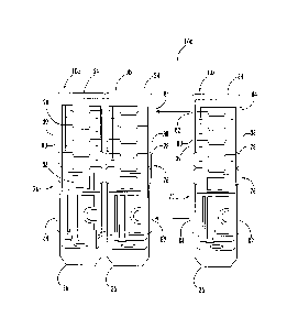
A pocket hole jig for locating pocket holes in a workpiece includes a base
with a base
plate and first and second side walls extending along the base plate, and a
body disposed
between the first and second side walls and slidable along the base in a
forward direction and a
rearward direction. The body includes a drill bit aperture angled downward
toward the base
plate. The pocket hole jig also includes a fastener configured to releasably
couple the pocket
hole jig to an adjacent second pocket hole jig.


Claims

Note: Claims are shown in the official language in which they were submitted.


CLAIMS
What is claimed is:
1. A pocket hole jig for locating pocket holes in a workpiece, the pocket
hole jig
comprising:
a base including a base plate and first and second side walls extending along
the base
plate;
a body disposed between the first and second side walls and slidable along the
base in a
forward direction and a rearward direction, the body including a drill bit
aperture angled
downward toward the base plate; and
a fastener configured to releasably couple the pocket hole jig to an adjacent
second
pocket hole jig.
2. The pocket hole jig of claim 1, wherein the body includes a window in
communication
with the drill bit aperture.
3. The pocket hole jig of claim 1, wherein the base includes a base
aperture extending
through the base plate and in communication with the drill bit aperture.
4. The pocket hole jig of claim 1, wherein the body is slideable rearward
past an open back
end of the base.
5. The pocket hole jig of claim 1, wherein the fastener includes a recess
and a projection
spaced from the recess.
6. The pocket hole jig of claim 1,
wherein the fastener is a first fastener located on the first side wall, and
wherein the pocket hole jig further comprises a second fastener located on the
second
side wall.
6

7. The pocket hole jig of claim 6,
wherein the first fastener is configured to releasably couple the pocket hole
jig to the
second pocket hole jig when the second pocket hole jig is positioned adjacent
the first side wall,
and
wherein the second fastener is configured to releasably couple the pocket hole
jig to a
third pocket hole jig when the third pocket hole jig is positioned adjacent
the second side wall.
8. The pocket hole jig of claim 6,
wherein the first fastener includes a first projection, a first recess spaced
from the first
projection, and a ferromagnetic portion disposed between the first projection
and the first recess,
and
wherein the second fastener includes a second projection, a second recess
spaced from
the second projection, and a magnet disposed between the second projection and
the second
recess.
9. The pocket hole jig of claim 8, wherein a size and shape of the first
projection
corresponds with a size and shape of the second recess, and wherein a size and
shape of the
second projection corresponds with a size and shape of the first recess.
10. The pocket hole jig of claim 1, wherein the body includes indicia
corresponding to a
thickness of the workpiece, wherein at least one of the first side wall and
the second side wall
includes a marking, and wherein the marking and the indicia together indicate
a position of the
body relative to the base.
11. The pocket hole jig of claim 1, wherein the fastener is configured to
magnetically couple
the pocket hole jig to the second pocket hole jig.
7

12. A pocket hole jig assembly for locating pocket holes in a workpiece,
the pocket hole jig
assembly comprising:
a first pocket hole jig including
a first base with first and second side walls,
a first body disposed between the first and second side walls, the first body
including a first drill bit aperture angled downward toward the first base,
and
a first fastener located on the second side wall; and
a second pocket hole jig including
a second base with third and fourth side walls,
a second body disposed between the third and fourth side walls, the second
body
including a second drill bit aperture angled downward toward the second base,
and
a second fastener located on the third side wall,
wherein the first fastener is engageable with the second fastener to
releasably couple the
first pocket hole jig to the second pocket hole jig with the first base
adjacent the second base.
13. The pocket hole jig assembly of claim 12, wherein the first fastener
includes a first recess
and a first projection spaced from the first recess, and wherein the second
fastener includes a
second recess and a second projection spaced from the second recess.
14. The pocket hole jig assembly of claim 13,
wherein the first fastener includes a magnet disposed between the first
projection and the
first recess, and
wherein the second fastener includes a ferromagnetic portion disposed between
the
second projection and the second recess.
15. The pocket hole jig assembly of claim 13, wherein a size and shape of
the first projection
corresponds with a size and shape of the second recess, and wherein a size and
shape of the
second projection corresponds with a size and shape of the first recess.
8

16. The pocket hole jig assembly of claim 12, wherein the first fastener
and the second
fastener are configured to magnetically couple the first pocket hole jig to
the second pocket hole
jig.
17. The pocket hole jig assembly of claim 12, wherein the second pocket
hole jig includes a
third fastener located on the fourth side wall, and wherein the pocket hole
jig assembly further
comprises:
a third pocket hole jig including
a third base with fifth and sixth side walls,
a third body disposed between the fifth and sixth side walls, the third body
including a third drill bit aperture angled downward toward the third base,
and
a fourth fastener located on the fifth side wall, and
wherein the third fastener is engageable with the fourth fastener to
releasably couple the
third pocket hole jig to the second pocket hole jig with the third base
adjacent the second base
such that the second pocket hole jig is between the first pocket hole jig and
the third pocket hole
jig.
18. The pocket hole jig assembly of claim 17, wherein the first fastener,
the second fastener,
the third fastener, and the fourth fastener each includes a projection, a
recess spaced from the
projection, and a magnet or a ferromagnetic portion disposed between the
projection and the
recess.
9

19. A method of releasably coupling a first pocket hole jig to a second
pocket hole jig, the
first pocket hole jig including a first base supporting a first body movable
relative to the first
base, the second pocket hole jig including a second base supporting a second
body movable
relative to the second base, each of the first and second bodies having a
downwardly angled drill
bit aperture, the method comprising:
positioning the first base adjacent the second base and aligning a first
fastener on the first
base with a second fastener on the second base; and
engaging the first fastener with the second fastener.
20. The method of claim 19, wherein engaging the first fastener with the
second fastener
includes inserting a projecting portion of the second fastener into a recess
of the first fastener.

Description

Note: Descriptions are shown in the official language in which they were submitted.


POCKET HOLE JIG
CROSS-REFERENCE TO RELATED APPLICATIONS
[0001] This application claims priority to co-pending U.S. Provisional
Patent Application
No. 62/453,089, filed on February 1, 2017, the entire content of which is
incorporated herein by
reference.
FIELD OF THE INVENTION
[0002] The present invention relates to pocket hole jigs.
BACKGROUND OF THE INVENTION
[0003] It is often desirable to drill two or more pocket holes in a
workpiece. It can be
difficult and time consuming to drill two adjacent holes separated by a
predetermined distance
using a single pocket hole jig.
SUMMARY OF THE INVENTION
[0004] The present invention provides, in one aspect, a pocket hole jig for
locating pocket
holes in a workpiece. The pocket hole jig includes a base with a base plate
and first and second
side walls extending along the base plate, and a body disposed between the
first and second side
walls and slidable along the base in a forward direction and a rearward
direction. The body
includes a drill bit aperture angled downward toward the base plate. The
pocket hole jig also
includes a fastener configured to releasably couple the pocket hole jig to an
adjacent second
pocket hole jig.
[0005] The present invention provides, in another aspect, a pocket hole jig
assembly for
locating pocket holes in a workpiece. The pocket hole jig assembly includes a
first pocket hole
jig having a first base with first and second side walls, a first body
disposed between the first and
second side walls, the first body including a first drill bit aperture angled
downward toward the
first base, and a first fastener located on the second side wall. The pocket
hole jig assembly
further includes a second pocket hole jig having a second base with third and
fourth side walls, a
second body disposed between the third and fourth side walls, the second body
including a
1
CA 2993734 2018-02-01

second drill bit aperture angled downward toward the second base, and a second
fastener located
on the third side wall. The first fastener is engageable with the second
fastener to releasably
couple the first pocket hole jig to the second pocket hole jig with the first
base adjacent the
second base.
[0006] The present invention provides, in another aspect, a method of
releasably coupling a
first pocket hole jig to a second pocket hole jig. The first pocket hole jig
includes a first base
supporting a first body movable relative to the first base, and the second
pocket hole jig includes
a second base supporting a second body movable relative to the second base.
Each of the first
and second bodies has a downwardly angled drill bit aperture. The method
includes positioning
the first base adjacent the second base and aligning a first fastener on the
first base with a second
fastener on the second base. The method also includes engaging the first
fastener with the
second fastener.
[0007] Other features and aspects of the invention will become apparent by
consideration of
the following detailed description and accompanying drawings.
BRIEF DESCRIPTION OF THE DRAWINGS
[0008] Fig. 1 is a perspective view of a pocket hole jig according to an
embodiment of the
invention.
[0009] Fig. 2 is another perspective view of the pocket hole jig of Fig. 1.
[0010] Fig. 3 is another perspective view of the pocket hole jig of Fig. 1.
[0011] Fig. 4 is a top view of multiple pocket hole jigs of Fig. 1, forming
a pocket hole jig
assembly.
[0012] Fig. 5 is a perspective view of the pocket hole jig assembly of Fig.
4.
[0013] Fig. 6 is a perspective view of a first workpiece including pocket
holes formed using
the pocket hole jig of Fig. 1.
2
CA 2993734 2018-02-01

[0014] Before any embodiments of the invention are explained in detail, it
is to be
understood that the invention is not limited in its application to the details
of construction and the
arrangement of components set forth in the following description or
illustrated in the following
drawings. The invention is capable of other embodiments and of being practiced
or of being
carried out in various ways.
DETAILED DESCRIPTION
[0015] Fig. 1 is a perspective view of a pocket hole jig 10. Referring to
Fig. 6, the jig 10 is
used to properly locate pocket holes 12, 16 in a workpiece 18, such as a piece
of wood. The
holes 12, 16 each receive a pocket screw 19 that is used to attach the
workpiece 18 to a second
workpiece.
[0016] Referring to Fig. 1, the jig 10 includes a base 20 and a body 22
movable relative to
the base 20. The body 22 includes a drill bit aperture 24 (Fig. 3), a window
26, and indicia 28.
The aperture 24 is angled downwardly toward the base 20 at an oblique angle
and is shaped and
sized to receive and guide a drill bit. When a drill bit is inserted through
the aperture 24, the bit
extends through an aperture 30 (Fig. 3) in the base 20 to drill into the
workpiece 18. The
window 26 is provided so that a user can see the drill bit traveling through
the aperture 24 and
into the workpiece and so that debris (e.g., wood chips) created by the drill
bit can exit the jig 10.
The aperture 30 and the window 26 are in communication with, or intersect, the
drill bit aperture
24.
[0017] The base 20 includes a base plate 31 and a generally U-shaped front
wall 34
extending upward from the base plate 31. The front wall 34 defines a
forwardmost or front
surface of the base 20. A back end 36 of the base 20 does not include a wall,
such that the back
end 36 is open. Lateral side walls 38, 39 extend upward from the base plate
31, from the front
wall 34 toward the back end 36.
[0018] The body 22 is disposed between the lateral side walls 38, 39 such
that the body 22
can slide forward (i.e. in the direction of arrow 40) and rearward (i.e. in
the direction of arrow
42) relative to the base 20 (Fig. 1). Forward movement of the body 22 is
limited by the front
wall 34, while the open back end 36 permits the body 22 to be completely
withdrawn from the
3
CA 2993734 2018-02-01

base 20. In some embodiments, a retaining member (e.g., a projection) may
limit rearward
movement of the body 22 to prevent the body from being separated from the base
20.
[0019]
Friction between the base 20 and body 22 holds the body 22 in position
relative to the
base 20 until the user exerts sufficient force to slide the body 22. In some
embodiments, the body
22 may include a projection or projections and the base 20 may include a
series of recesses that
receive the projection(s) to releasably hold the body 22 in the desired
position relative to the base
20. The side walls 38, 39 each include a marking 47 (e.g., an arrow in
illustrated embodiment).
The marking 47 and indicia 28 of the body 22 indicate to the user the relative
position of the
body 22 relative to the base 20. The indicia 28 include a plurality of lines
that each correspond
to a particular thickness 46 (Fig. 6) of the workpiece 18 (e.g., 3/4 inch, 1
inch, 1-1/4 inch, etc.).
That is, the user can position the body 22 relative to the base 20 by aligning
the arrow 47 to the
indicia 28 that corresponds to the thickness 46 of the workpiece 18.
[0020]
Referring to Figs. 1 and 2, the base 20 further includes fasteners 76 on each
side wall
38, 39 to couple the jig 10 to other jigs 10 (Fig. 4). In the illustrated
embodiment the fastener 76
of the first side 38 includes a ferromagnetic portion or metal strip 78, a
recess 82, and a
projection 84. The illustrated fastener 76 of the second side 39 includes a
magnet 80, a recess
82, and a projection 84. The size and shape of each recess 82 corresponds with
the size and shape
of each projection 84. In some embodiments, the positions of the recesses 82
and projections 84
may be reversed. In some embodiments, the first side 38 may include the magnet
80, and the
second side 39 may include the metal strip 78. In other embodiments, other
suitable types of
fasteners can be used to releaseably couple the jig 10 to adjacent jigs.
[0021]
Referring to Figs. 4 and 5, multiple jigs 10 (i.e. a first jig 10a, a second
jig 10b, and a
third jig 10c) can be releasably coupled together via the fasteners 76 to form
a pocket hole jig
assembly 100. That is, the metal strip 78 of the first jig 10a is placed
adjacent the magnet 80 of a
second jig 10b to magnetically couple the first jig 10a to the second jig 10b.
Meanwhile, the
recesses 82 receive and engage the adjacent projections 84 to properly align
the jigs 10a, 10b
relative to each other. As illustrated in Figs. 4 and 5, two, three, or more
jigs 10a, 10b, 10c can
be connected. For example, the first jig 10a can be coupled to the second jig
10b with the base
20 and particularly the first side wall 38 of the second jig 10b positioned
adjacent the base 20
4
CA 2993734 2018-02-01

and particularly the second side wall 39 of the first jig 10a. The third jig
10c can be coupled to
the second jig 10b with the base 20 and particularly the first side wall 38 of
the third jig 10c
positioned adjacent the base 20 and particularly the second side wall 39 of
the second jig lob.
Thus, the second jig 10b can be positioned between the first jig 10a and the
third jig 10c. It
should be understood that the jigs 10a, 10b, 10c can be coupled together in a
variety of different
relative positions.
[0022] As illustrated in Fig. 6, it is often desirable to drill two or more
pocket holes 12, 16 in
the workpiece 18. The fasteners 76 of the jigs 10 allow the user to quickly
and easily couple
multiple jigs 10 to properly and neatly align multiple pocket holes 12, 16 at
a predetermined
spacing D.
[0023] Various features of the invention are set forth in the following
claims.
CA 2993734 2018-02-01

Representative Drawing
A single figure which represents the drawing illustrating the invention.
Administrative Status

2024-08-01:As part of the Next Generation Patents (NGP) transition, the Canadian Patents Database (CPD) now contains a more detailed Event History, which replicates the Event Log of our new back-office solution.

Please note that "Inactive:" events refers to events no longer in use in our new back-office solution.

For a clearer understanding of the status of the application/patent presented on this page, the site Disclaimer , as well as the definitions for Patent , Event History , Maintenance Fee  and Payment History  should be consulted.

Event History

Description Date
Letter Sent 2024-06-03
Notice of Allowance is Issued 2024-06-03
Inactive: Approved for allowance (AFA) 2024-05-28
Inactive: Q2 passed 2024-05-28
Letter Sent 2023-02-22
Request for Examination Received 2023-01-31
Request for Examination Requirements Determined Compliant 2023-01-31
Amendment Received - Voluntary Amendment 2023-01-31
All Requirements for Examination Determined Compliant 2023-01-31
Amendment Received - Voluntary Amendment 2023-01-31
Common Representative Appointed 2020-11-07
Common Representative Appointed 2019-10-30
Change of Address or Method of Correspondence Request Received 2019-07-24
Inactive: Office letter 2019-07-11
Letter Sent 2019-04-30
Inactive: Correspondence - Formalities 2019-04-11
Correct Applicant Request Received 2019-04-11
Inactive: Single transfer 2019-04-11
Inactive: Reply to s.37 Rules - Non-PCT 2019-04-11
Letter Sent 2018-09-21
Inactive: Single transfer 2018-09-18
Application Published (Open to Public Inspection) 2018-08-01
Inactive: Cover page published 2018-07-31
Inactive: IPC assigned 2018-02-21
Inactive: First IPC assigned 2018-02-21
Inactive: IPC assigned 2018-02-21
Inactive: Filing certificate - No RFE (bilingual) 2018-02-15
Application Received - Regular National 2018-02-08

Abandonment History

There is no abandonment history.

Maintenance Fee

The last payment was received on 2024-01-26

Note : If the full payment has not been received on or before the date indicated, a further fee may be required which may be one of the following

  • the reinstatement fee;
  • the late payment fee; or
  • additional fee to reverse deemed expiry.

Patent fees are adjusted on the 1st of January every year. The amounts above are the current amounts if received by December 31 of the current year.
Please refer to the CIPO Patent Fees web page to see all current fee amounts.

Fee History

Fee Type Anniversary Year Due Date Paid Date
Application fee - standard 2018-02-01
Registration of a document 2018-09-18
Registration of a document 2019-04-11
MF (application, 2nd anniv.) - standard 02 2020-02-03 2020-01-24
MF (application, 3rd anniv.) - standard 03 2021-02-01 2021-01-22
MF (application, 4th anniv.) - standard 04 2022-02-01 2022-01-28
MF (application, 5th anniv.) - standard 05 2023-02-01 2023-01-27
Request for examination - standard 2023-02-01 2023-01-31
MF (application, 6th anniv.) - standard 06 2024-02-01 2024-01-26
Owners on Record

Note: Records showing the ownership history in alphabetical order.

Current Owners on Record
TTI (MACAO COMMERCIAL OFFSHORE) LIMITED
Past Owners on Record
CLINTON C. THACKERY
DREW A. DAHILL
HARRISON S. MCSPADDEN
JACOB F. CREASMAN
RICHARD M. DAVIDIAN
THOMAS EVATT
Past Owners that do not appear in the "Owners on Record" listing will appear in other documentation within the application.
Documents

To view selected files, please enter reCAPTCHA code :


To view images, click a link in the Document Description column (Temporarily unavailable). To download the documents, select one or more checkboxes in the first column and then click the "Download Selected in PDF format (Zip Archive)" or the "Download Selected as Single PDF" button.

List of published and non-published patent-specific documents on the CPD .

If you have any difficulty accessing content, you can call the Client Service Centre at 1-866-997-1936 or send them an e-mail at CIPO Client Service Centre.

({010=All Documents, 020=As Filed, 030=As Open to Public Inspection, 040=At Issuance, 050=Examination, 060=Incoming Correspondence, 070=Miscellaneous, 080=Outgoing Correspondence, 090=Payment})


Document
Description 
Date
(yyyy-mm-dd) 
Number of pages   Size of Image (KB) 
Description 2023-01-30 5 299
Abstract 2018-01-31 1 13
Description 2018-01-31 5 221
Claims 2018-01-31 5 154
Drawings 2018-01-31 6 129
Representative drawing 2018-06-25 1 11
Claims 2023-01-30 5 222
Maintenance fee payment 2024-01-25 46 1,890
Commissioner's Notice - Application Found Allowable 2024-06-02 1 575
Courtesy - Certificate of registration (related document(s)) 2018-09-20 1 106
Filing Certificate 2018-02-14 1 203
Courtesy - Certificate of registration (related document(s)) 2019-04-29 1 107
Reminder of maintenance fee due 2019-10-01 1 111
Courtesy - Acknowledgement of Request for Examination 2023-02-21 1 423
Response to section 37 2019-04-10 9 259
Courtesy - Office Letter 2019-07-10 1 47
Request for examination / Amendment / response to report 2023-01-30 11 359