Note: Descriptions are shown in the official language in which they were submitted.
DAMAGE ASSESSMENT AND REPORTING SYSTEM
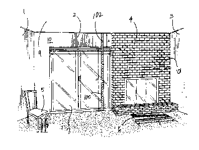
[0001]
This application is a division of Canadian Patent Application No. 2,885,020
filed March 13, 2015.
TECHNICAL FIELD
[0002] The
technology disclosed herein relates generally to a system for generating
scale diagrams of an area, structure, or object using photographs and is
particularly directed
to computerized system of the type which uses scale diagrams generated from
photographs
to efficiently process loss claims including, without limitation, casualty
insurance claims.
[0003]
BACKGROUND
[0004]
Many insured property damage claims require a physical inspection by at
least one adjuster. Such adjusters, who are frequently employees or
contractors of an
insurance provider, physically inspect insured property in order to assess
damages and
process applicable insurance claims. Many insurance providers have so-called
"fast track"
claims which allow for processing of property damage claims without conducting
on-site
inspections. However, such fast track claims are typically processed without
significant
information regarding the property at issue, as well as the nature and extent
of the alleged
damages. As a result, such existing fast track claims are typically highly
vulnerable to
1
CA 2993788 2018-02-02
inaccuracies and/or inequities in the claims adjustment process. Moreover,
such fast track
claims currently represent a fairly small percentage of property damage
insurance claims.
[0005] Every
on-site inspection has inherent costs, whether such inspection is
performed by an insurance company employee or a third-party contractor. Such
costs can
include direct expenses, such as adjustor salaries or contractor fees.
However, such
inspection costs can also include other expenses, such as vehicle, fuel,
maintenance, vacation
and benefit costs, as well as workers compensation insurance. Physical
inspections also
expose company and contract adjustors to a risk of personal injury or death,
particularly at
property locations that have suffered significant damage.
[0006]
Physical inspections, which are also time consuming and labor intensive, can
also substantially delay the claim adjusting process. Such delay is especially
common during
times of higher claims volume, such as following extreme weather events or
natural disasters
when multiple property locations are damaged or destroyed. This delay can have
a
detrimental effect on customer service and customer satisfaction.
[0007] Thus,
there is a need for an improved system for processing property
loss/casualty claims that increases efficiency and lowers costs. The method
should provide
information to allow an insurer to determine whether an on-site physical
inspection is
required. In cases where such physical inspection is not required, the
improved system for
processing property loss/casualty claims should permit generation of scale
diagrams of an
area, structure, or object using photographs, as well as the use of such scale
diagrams in
connection with the claim processing procedure.
SUMMARY
[0008] The
technology disclosed herein significantly increases the number of "fast
track" loss/casualty claims (while reducing costs associated with inspection
claims), while
maintaining the integrity of the claim adjusting process. Furthermore, the
technology
disclosed herein can substantially speed up the claims adjusting process,
while improving
customer service, customer involvement and overall satisfaction.
Additionally, the
technology disclosed herein can be used by both inside adjusters and field
adjusters.
2
CA 2993788 2018-02-02
[0009] The technology
disclosed herein allows inside adjusters to accurately diagram
rooms, structures and objects without performing a physical on-site inspection
by using
photographs, including photographs submitted via email or over the internet.
Such
photographs can be provided by a property owner (or other source) and used by
an inside
adjustor to process a claim without the need for physically inspecting a
location.
[0010] Even when on-
site inspection is required, the technology disclosed herein
allows field adjusters to expedite the inspection process by eliminating the
need for
diagramming a property while actually on location, thereby allowing an
adjustor to inspect
more properties during a given time period. Such efficiency is particularly
important during
times of higher claims volume, such as following extreme weather or natural
disasters when
multiple property locations are damaged or destroyed by a common event. The
technology
disclosed herein also improves safety by reducing the amount of time that a
field adjustor is
required to remain on-site at a damaged location.
[0011] In accordance
with the technology disclosed herein, photographs of a damaged
property are initially obtained. Where possible, such photographs can be taken
by a property
owner or other person acting on behalf of said property owner. However, it is
to be observed
that in certain circumstances, an adjustor or other inspector may be required
to travel to a
location in order to obtain such photographs.
[0012] Once obtained,
such photographs can be sent to a claim processing facility,
whether by physical delivery, electronic mail, intemet submission, or other
method. In many
cases, such photographs are organized by room, structure or object in
question. Such
photographs are then uploaded to a computer having a processor; when only
printed copies of
photographs are provided, such photographs can be scanned or otherwise
digitized in order to
facilitate such uploading process.
[0013] After
such photographs have been uploaded to a computer having a processor,
a base calibration measure is obtained for a particular room, structure,
object or component
thereof depicted in such photographs using at least one known dimension for
items
observable in such photographs. Although such known dimensions can be obtained
from any
number of different sources, in the preferred embodiment said known dimensions
are
obtained from standards existing for particular items. By way of illustration,
but not
limitation, such standard dimensions can be obtained from building codes (or
other rules or
3
CA 2993788 2018-02-02
regulations established by applicable governmental or regulatory agencies),
manufacturer
specifications, manufacturing standards, or other sources. For example, such
standard
dimensions can include, without limitation, door heights, bricks, kitchen
sinks, furniture
items and the like.
[0014] After
said base calibration measure has been determined using said at least one
known dimension, said base calibration measure can then be used to determine
dimensions of
other areas, items or objects depicted in such photographs. Thereafter, said
dimensions can
be utilized to create at least one scale diagram of a room, area, structure or
object in question.
In additional to diagramming a room, areas, structure or object, visible or
known damaged
areas, surfaces and/or materials can be measured in order to determine the
extent of repairs or
replacement required.
[0015] Such
scale diagrams can then be used to calculate an appropriate insurance
payment amount. Frequently, such scale diagrams can be uploaded into
conventional
estimating computer software commonly used to calculate insurance payments
well known to
those having skill in the art of adjusting property damage claims. By way of
example, such
conventional estimating software can include, without limitation, commercially
available
estimating software marketed under the trademarks "Xactimate" or "Symbility",
or such
other software as may provide desired output information. Where applicable,
deductions for
openings (windows, doors, missing walls) and other features associated with
said rooms,
structures or other objects depicted in such scale diagrams can be taken into
account when
calculating such insurance payment.
[0016]
Although the technology disclosed herein is described herein primarily in
connection with the processing of insurance claims, it is to be observed that
the technology
disclosed herein has utility in a wide range of other applications and/or
industries. For
example, the present technology can benefit non-insurance applications
including, without
limitation, real estate, interior design, remodeling/reconstruction, security
and other industries
that require or can utilize scale diagrams of areas, structures or other
objects.
[0017] It is
an advantage of the technology disclosed herein to provide a
computerized system that allows photographs of damaged structures to be sent
to a claims
representative of an insurance company, and to have a claims representative or
other
employee of an insurance company use operating software to manipulate the
photographic
4
CA 2993788 2018-02-02
data to discern with good accuracy the amount of damaged areas and the amount
of original
un-damaged areas of a structure such as a dwelling or a vehicle, to quickly
and accurately
create damage estimates used in handling insurance claims.
[0018] It is another advantage of the technology disclosed herein to
provide an
E4thDTM processing center that receives photographic information from an
insured person
or from a claims representative, to manipulate the photographic data to create
accurate
damage assessments for structures that are insured, and to contact insurance
company
computer centers to create accurate insurance claims for those damaged
structures.
[0019] It is a further advantage of the technology disclosed herein
to provide operating
software that can be used by a claims representative that will receive
photographic information
and create accurate damage estimates for damaged structures, and that can be
used to contact
insurance companies to create claims that can be quickly settled by a claims
adjuster using the
accurate information gleaned from the photographic information.
[0020] It yet another advantage of the technology disclosed herein
to provide E4thD
operating software that can be used at an insurance company's computing
center, such that
photographic information can be received from insured persons or from claims
representatives, in
which that photographic information can be used to quickly and accurately
create damage estimates
that will allow the insurance company to quickly settle claims for such
damaged structures.
[0021] Additional advantages and other novel features will be set
forth in part in the
description that follows and in part will become apparent to those skilled in
the art upon examination of
the following or may be learned with the practice of the technology disclosed
herein.
[0022] To achieve the foregoing and other advantages, and in
accordance with one aspect, a
computerized system for determining physical attributes of a physical
structure is provided, which
comprises: (a) a processing circuit; (b) a memoty circuit; (c) a
communications circuit; (d) a visual
monitor; (e) a user-controlled data entry device; wherein: the processing
circuit is configured: (f) to
receive photographic information through the communications circuit; (g) to
display, on the visual
monitor, an image based on the photographic information, the image containing
image data; (h) to allow a
user, while viewing the image: (i) to select an object, using the data entry
device, that is contained in the
CA 2993788 2018-02-02
image; (ii) to graphically draw a first line that corresponds to a particular
dimension of the
object, the first line having a first distance as its length on the visual
monitor, which is then
used as a base calibration measure; (iii) to store the first distance in the
memory circuit, in
units of GUI coordinate data; (iv) to graphically change the length of the
first line so that it
becomes a second line having a second distance as its length, the second
distance spanning a
different particular dimension on the image; (v) to store the second distance
in the memory
circuit, in units of GUI coordinate data; (vi) to assign an actual distance in
engineering units
to the base calibration measure, and to store the actual distance in the
memory circuit; (i) to
convert distances that initially are in terms of units of GUI coordinate data
into distances that
are in terms of engineering units; and (j) to automatically scale the second
distance into
engineering units.
[0023] In
accordance with another aspect, a computerized system for determining
physical attributes of a physical structure is provided, which comprises: (a)
a processing
circuit; (b) a memory circuit; (c) a communications circuit; (d) a visual
monitor; (e) a user-
controlled data entry device; wherein: the processing circuit is configured:
(f) to receive
photographic information through the communications circuit; (g) to display,
on the visual
monitor, an image based on the photographic information, the image containing
image data;
(h) to allow a user, while viewing the image: (i) to select an object, using
the data entry
device, that is contained in the image; (ii) to graphically draw a first line
that corresponds to a
particular dimension of the object, the first line having a first distance as
its length on the
visual monitor, which is then used as a base calibration measure; (iii) to
store the first
distance in the memory circuit, in units of GUI coordinate data; (iv) to
graphically draw a
second line having a second distance as its length, the second distance
spanning a different
particular dimension on the image; (v) to store the second distance in the
memory circuit, in
units of GUI coordinate data; (vi) to assign an actual distance in engineering
units to the base
calibration measure, and to store the actual distance in the memory circuit;
(i) to convert
distances that initially are in terms of units of GUI coordinate data into
distances that are in
terms of engineering units; and (j) to automatically scale the second distance
into engineering
units.
[0024] In
accordance with a further aspect, a computerized system for determining
physical attributes of a physical structure is provided, which comprises: (a)
a first
computerized device, comprising: (i) a first processing circuit; (ii) a first
memory circuit; (iii)
6
CA 2993788 2018-02-02
a first communications circuit; (iv) a first display device; (v) a first user-
controlled data entry
device; (vi) at least one of: (A) a camera, and (B) an optical scanner; (vii)
a first computer
program that executes on the first processing circuit; (b) a second
computerized device,
comprising: (i) a second processing circuit; (ii) a second memory circuit;
(iii) a second
communications circuit; (iv) a second display device; (v) a second user-
controlled data entry
device; (vi) a second computer program that executes on the second processing
circuit; (c) a
third computerized device, comprising: (i) a third processing circuit; (ii) a
third memory
circuit; (iii) a third communications circuit; (iv) a third display device;
(v) a third user-
controlled data entry device; (vi) a third computer program that executes on
the third
processing circuit; (d) at least one communications network that allows the
first, second, and
third communications circuits to transfer data to and from external computer
devices;
wherein: (e) the first processing circuit, executing the first computer
program, is configured:
(i) to cause image data received at the first communications circuit, from the
at least one of a
camera and a scanner, under control of a first user, to be stored in the first
memory circuit;
(ii) to transmit the image data, using the first communications circuit, to
the second
computerized device; (f) the second processing circuit, executing the second
computer
program, is configured: (i) to cause the image data received at the second
communications
circuit, from the first computerized device, to be stored in the second memory
circuit; (ii) to
allow a second user: (A) to view the image data on the second display device;
(B) to
graphically draw a first line that corresponds to a particular dimension of an
object, as
selected by the second user, that appears in the image data, and thereafter
use the first line as
a base calibration measure; (C) to store the base calibration measure in the
second memory
circuit; (D) to graphically draw a second line having a second distance as its
length, the
second distance spanning a different particular dimension on the image data,
as selected by
the second user; (E) to assign an actual distance in engineering units to the
base calibration
measure, and to convert the second distance that initially was in terms of
units of GUI
coordinate data into a distance that is in terms of engineering units; (F) to
automatically scale
the entire image, in units of GUI coordinate data, into engineering units, and
thereby create a
scale diagram; (G) to select a first area that corresponds to a total area of
a specific structure
that appears in the image, using the second user-controlled data entry device;
(H) to select a
second area that corresponds to at least one area of damage that is visible in
the image, using
the second user-controlled data entry device; (iii) to calculate the first
area in terms of
engineering units, to calculate the second area in terms of engineering units,
and to store
results of the first area and second area calculations in the second memory
circuit; (iv) to
7
CA 2993788 2018-02-02
transmit the results, using the second communications circuit, to the third
computerized
device; and (e) the third processing circuit, executing the third computer
program, is
configured: (i) to cause the results received at the third communications
circuit, from the
second computerized device, to be stored in third second memory circuit; (ii)
to allow a third
user: (A) to review the results to identify an insured property; (B) to
inspect information
about the insured property that is stored in the third memory circuit, to
determine a value of
the insured property; and (C) to use the results to assess a damage value of
the at least one
area of damage.
[0025] Still
other advantages will become apparent to those skilled in this art from the
following description and drawings wherein there is described and shown a
preferred
embodiment in one of the best modes contemplated for carrying out the
technology. As will
be realized, the technology disclosed herein is capable of other different
embodiments, and its
several details are capable of modification in various, obvious aspects all
without departing
from its principles. Accordingly, the drawings and descriptions will be
regarded as
illustrative in nature and not as restrictive.
BRIEF DESCRIPTION OF THE DRAWINGS
[0026] The
foregoing summary, as well as any detailed description of the preferred
embodiments, is better understood when read in conjunction with the drawings
and figures
contained herein. For the purpose of illustrating the technology disclosed
herein, the drawings
and figures show certain preferred embodiments. It is understood, however,
that the
technology is not limited to the specific methods and devices disclosed in
such drawings or
figures.
[0027] The
accompanying drawings incorporated in and forming a part of the
specification illustrate several aspects of the technology disclosed herein,
and together with
the description and claims serve to explain the principles of the technology.
In the drawings:
[0028] FIG.
1 depicts a digital image of a photograph showing a perspective view of
an internal space of a structure that can be diagrammed using the method of
the technology
disclosed herein.
8
CA 2993788 2018-02-02
[0029] FIG.
2 depicts a digital image of a photograph showing an alternate
perspective view of the internal space of a structure depicted in FIG. 1.
[0030] FIG.
3 depicts a digital image of a photograph showing a perspective view of a
first portion of an internal space of a structure that can be diagrammed using
the method of
the technology disclosed herein.
[0031] FIG.
4 depicts a digital image of a photograph of a perspective view of a
second portion of an internal space of a structure depicted in FIG. 3.
[0032] FIG.
5 is a block diagram of the major components of a personal computer
system, as constructed and used according to the principles of the technology
disclosed
herein.
[0033] FIG.
6 is a block diagram of the major components of a smartphone system, as
constructed and used according to the principles of the technology disclosed
herein.
[0034] FIG.
7 is a block diagram of the major components of a tablet computer
system, as constructed and used according to the principles of the technology
disclosed
herein.
[0035] FIG.
8 is a block diagram of the major components of an E4thD processing
center system, as constructed according to the principles of the technology
disclosed herein.
[0036] FIG.
9 is a block diagram of the major components of an E4thD system in
which a claims representative is the E4thD operator, as constructed and used
according to the
principles of the technology disclosed herein.
[0037] FIG.
10 is a block diagram of the major components of an insurance
company's computer center, used as an E4thD operator system, as constructed
and used
according to the principles of the technology disclosed herein.
[0038] FIG.
11 is a flow chart of some of the important steps performed by persons
who take photographs of damaged structures, and of steps performed by a user
operating an
E4thD operating system, as constructed and used according to the principles of
the
technology disclosed herein.
9
CA 2993788 2018-02-02
[0039] FIGS. 12 and 13
combined are a flow chart showing some of the important
steps for entering a claim to an insurance company for property damage as
performed by
insured persons entering a fast track claim, or by desk adjusters or field
adjusters, according
to the principles of the technology disclosed herein.
[0040] FIG. 14 depicts
a computer-generated visual display, showing an initial step
for developing a scale diagram of a structure, using a second embodiment of
the technology
disclosed herein.
[0041] FIG. 15 depicts
a computer-generated visual display, showing a perspective
view of an internal space of a structure that can be diagrammed using computer
software-
controlled graphical techniques that are implemented by the second embodiment
of the
technology disclosed herein.
[0042] FIG. 16 depicts
the visual display of FIG. 15, showing a standard object being
selected for use in calibration.
[0043] FIG. 17 depicts
the visual display of FIG. 16, showing the exact size of the
standard object being selected for use in calibration.
[0044] FIG. 18 depicts
the visual display of FIG. 17, showing a height dimension now
being selected for conversion into engineering units.
[0045] FIG. 19 depicts
the visual display of FIG. 17, showing a width dimension now
being selected for conversion into engineering units.
DETAILED DESCRIPTION
[0046]
Reference will now be made in detail to the present preferred embodiment, an
example of which is illustrated in the accompanying drawings, wherein like
numerals
indicate the same elements throughout the views.
[0047] It is
to be understood that the technology disclosed herein is not limited in its
application to the details of construction and the arrangement of components
set forth in the
following description or illustrated in the drawings. The technology disclosed
herein is
capable of other embodiments and of being practiced or of being carried out in
various ways.
CA 2993788 2018-02-02
,
Also, it is to be understood that the phraseology and terminology used herein
is for the
purpose of description and should not be regarded as limiting. The use of
"including,"
"comprising," or "having" and variations thereof herein is meant to encompass
the items
listed thereafter and equivalents thereof as well as additional items. Unless
limited otherwise,
the terms "connected," "coupled," and "mounted," and variations thereof herein
are used
broadly and encompass direct and indirect connections, couplings, and
mountings. In
addition, the terms "connected" and "coupled" and variations thereof are not
restricted to
physical or mechanical connections or couplings.
[0048] The terms "first" and "second" preceding an element name, e.g.,
first inlet,
second inlet, etc., are used for identification purposes to distinguish
between similar or
related elements, results or concepts, and are not intended to necessarily
imply order, nor are
the terms "first" and "second" intended to preclude the inclusion of
additional similar or
related elements, results or concepts, unless otherwise indicated.
[0049] In addition, it should be understood that embodiments disclosed
herein include
both hardware and electronic components or modules that, for purposes of
discussion, may be
illustrated and described as if the majority of the components were
implemented solely in
hardware.
[0050] However, one of ordinary skill in the art, and based on a reading of
this
detailed description, would recognize that, in at least one embodiment, the
electronic based
aspects of the technology disclosed herein may be implemented in software. As
such, it
should be noted that a plurality of hardware and software-based devices, as
well as a plurality
of different structural components may be utilized to implement the technology
disclosed
herein.
[0051] It will be understood that the term "circuit" as used herein can
represent an
actual electronic circuit, such as an integrated circuit chip (or a portion
thereof), or it can
represent a function that is performed by a processing device, such as a
microprocessor or an
ASIC that includes a logic state machine or another form of processing element
(including a
sequential processing device). A specific type of circuit could be an analog
circuit or a
digital circuit of some type, although such a circuit possibly could be
implemented in
software by a logic state machine or a sequential processor. In other words,
if a processing
circuit is used to perform a desired function used in the technology disclosed
herein (such as
11
CA 2993788 2018-02-02
a demodulation function), then there might not be a specific "circuit" that
could be called a
"demodulation circuit;" however, there would be a demodulation "function" that
is performed
by the software. All of these possibilities are contemplated by the inventors,
and are within
the principles of the technology when discussing a "circuit."
[0052] Upon
notice of the existence of a claim to be processed, an initial
determination is made regarding whether an on-site inspection is required. If
so, then an
inspector can be dispatched to the location of the property at issue. If not,
then the claim can
be classified as a so-called "fast track" claim and handled accordingly.
[0053] In
accordance with the technology disclosed herein, photographs of a damaged
property are initially obtained. For "fast track" claims, specific
instructions can be provided
to a claimant, property owner, tenant or other interested party regarding
certain actions to be
taken including, without limitation, instructions regarding how to photograph
the property at
issue, label such photographs, and submit such photographs for further
handling. In many
case, such photographs (whether digital photos, or scanned or digitized
images) can be sent
by electronic mail or uploaded to a web site or other portal accessible via
the Internet.
[0054] When
physical inspection is performed, a field adjuster or inspector can visit
the property that is the subject of the claim. Said field adjustor or
inspector can then
photograph the property that is subject to the claims (frequently pursuant to
a method that is
similar to the instructions provided to claimants, property owners, tenants or
other interested
parties using "fast track" claim processing). Said field adjuster or inspector
can also takes
notes on damages or other observed conditions (commonly referred to in the
insurance
industry as a "tic sheet") and/or gather such other information from the
location as deemed
advisable under the circumstances.
[0055]
Regardless of how obtained (whether from an inspector or adjuster, or from a
claimant, property owner or tenant) such photographs are uploaded or otherwise
imported to
a computer having a processor. Such photographs can be beneficially organized
by room,
structure or object in question, or other desirable classification scheme.
[0056] After
such photographs have been uploaded or otherwise imported to a
computer having a processor, one or more digital images can be displayed via a
computer
monitor or other graphic interface. In the preferred embodiment, said digital
images depict
substantially the same view as said photographs; however, it is to be observed
that said digital
12
CA 2993788 2018-02-02
images can be zoomed, enhanced or otherwise digitally manipulated using means
well known
to those having skill in the art. A base calibration measure is obtained for
each particular
room, structure, object or component thereof depicted in such photographs
using at least one
known dimension for items observable in such photographs.
[0057]
Referring now to the drawings, in a first embodiment FIG. 1 depicts digital
image of a photograph of a perspective view of an internal space of a
structure 10 that can be
diagrammed using the method of the technology disclosed herein. As depicted in
FIG. 1,
structure 10 generally comprises walls 1, 2 and 3, and ceiling 9. Said
structure further
includes a brick hearth and fireplace 4, chair 5, rug 6 and doorway 7.
[0058] A
base calibration measure is generated by digitally (graphically) drawing a
line on said digital image using a computer and software of the technology
disclosed herein.
By way of illustration, and as depicted in FIG. 1, line 100 can be graphically
drawn from the
floor at the bottom of doorway 7 to the top of doorway 7. Said line 100 is
assigned a length
dimension ¨ depicted as dimension "B" on FIG. I - based upon a known standard
of the
height of doorway 7. For example, said calibration line 100 can be assigned a
length
dimension of 6'8" (based on standard doorway height as set forth in an
applicable local
building code), with digital calibration line 100 being scaled accordingly.
[0059]
Although such known dimensions can be obtained from any number of
different sources, in the preferred embodiment said known dimensions are
obtained from
standards existing for particular items. By way of illustration, but not
limitation, such
standard dimensions can be obtained from building codes (or other rules or
regulations
established by applicable governmental or regulatory agencies), manufacturer
specifications,
or other sources. For example, such standard dimensions can include, without
limitation,
door heights, bricks, kitchen sinks, furniture items and the like. In the
preferred embodiment,
one or more databases can be created for such known standards, which standards
can be
obtained from a variety of sources.
[0060] Still
referring to FIG. 1, said base calibration dimension B (and the associated
scale of line 100) can be confirmed using other known standards observable
within said
digital image of said photograph. For example, a line 101 can be graphically
drawn on said
digital image to correspond to the width of a brick in hearth/fireplace 4 and
assigned
dimension "D" (for example, 7-1/2"). Similarly, lines can be graphically drawn
on said
13
CA 2993788 2018-02-02
digital image to correspond to other known dimensions, such as a line 102
representing the
height of chair 5 (dimension "F"), a line 103 representing the width of
doorway 7 (dimension
"C") and a line 104 representing the width of rug 6 (dimension "E"). In this
manner, base
calibration dimension B can be confirmed by comparison to said other known
dimensions C,
D, E and F, and adjusted if required, based on such other dimensions (or other
known
dimensions measured from said image) to represent the most accurate base
calibration
dimension B and applicable scale for line 100.
[0061] Base
calibration line 100 having dimension B is fixed for use with said image,
with said dimension B being displayed on said digital image depicted in FIG.
1. After line
100 is fixed in length, it can be graphically moved, turned and/or otherwise
repositioned on
such image, as desired, in order to determine the dimensions of other unknown
items in FIG.
1. For example, calibration line 100 can be graphically placed in a desired
position, such as
the opening of doorway 7 on FIG. 1. A first end of said line 100 can be
graphically anchored
on the floor at the base of doorway 7, while the second end of said line 100
can be
"stretched" to the intersection of wall 2 and ceiling 9, thereby forming a
stretch line 105
having dimension "A". In the preferred embodiment, line 100 does not change in
length;
rather, stretch line 105 is displayed as a different color extending from the
second end of
calibration line 100 in order to graphically represent the additional length
of line 105 (and
dimension A) relative to line 100 (and dimension B).
[0062]
Dimension A can be determined using the length of line 105 and the scale
established by said base calibration line 100 and known dimension B.
Thereafter, the height
of said wall 2 (that is, the distance from the floor to the intersection of
wall 2 and ceiling 9)
can be determined as the sum of dimensions A and B. Similarly, other unknown
dimensions
can be calculated from said photographic image in substantially the same
manner using said
base calibration line 100 and dimension B. Specifically, line 100 can be
graphically moved,
turned and/or otherwise repositioned on such image (and then anchored, and
stretched/compressed), to determine other unknown dimensions depicted on said
photographic image.
[0063] In
the preferred embodiment, when an item or object larger than dimension B
is being measured on the image of FIG. 1, a stretch line is displayed as a
different color
extending from the non-anchored end of calibration line 100 in order to
graphically represent
the additional or incremental length of said stretch line relative to said
calibration line 100.
14
CA 2993788 2018-02-02
Conversely, when an item or object smaller than line 100 or dimension B is
being measured
on the image of FIG. 1, a parallel "subtraction line" is graphically displayed
adjacent to said
calibration line in a different color than line 100; said subtraction line
graphically represents
the reduction in length of the measured item/object compared to the original
length of
calibration line 100.
[0064] FIG. 2
depicts a digital image of an alternate perspective view of the internal
space of a structure 10 depicted in FIG. 1 including, without limitation, wall
3, ceiling 9, rug
6 and hearth/fireplace 4. Put another way, FIG. 2 depicts another perspective
of a different
portion of a room depicted in FIG. 1. In FIG. 2, a new base calibration line
200 having a
known distance is established on FIG. 2. Because the distance from floor to
ceiling in the
subject room was determined in FIG. 1 (as the sum of dimensions A and B), one
end of new
calibration line 200 can be anchored on the floor at the base of wall 3, while
the other end of
said line 200 can be stretched to the intersection of wall 3 and ceiling 9;
this new calibration
line 200 can then be assigned a known dimension "G" (equivalent to the sum of
dimensions
A and B determined in FIG. 1).
[0065] As
with FIG. 1, fixed-length calibration line 200 having a base calibration
dimension G can then be graphically moved, turned and/or otherwise
repositioned (and then
anchored, and stretched/compressed) on FIG. 2 to determine other unknown
dimensions
depicted on said photographic image. When an item or object larger than
dimension G is
being measured on the image of FIG. 2, a stretch line can be displayed as a
different color
extending from the non-anchored end of calibration line 200 in order to
graphically represent
the additional or incremental length of said stretch line relative to said
calibration line 200.
Conversely, when an item or object smaller than line 200 or dimension G is
being measured
on the image of FIG. 2, a parallel "subtraction line" is graphically displayed
adjacent to said
calibration line 200 in a different color than line 200; said subtraction line
graphically
represents the reduction in length of the smaller measured item/object
compared to the
original length of calibration line 200.
[0066] For
example, a first end of said calibration line 200 can be graphically
anchored at the intersection between walls 3 and 8, while the second end of
said calibration
line 200 can be graphically "stretched" to the intersection of wall 3 and
hearth/fireplace 4,
thereby forming a stretch line 201 having dimension "H". In the preferred
embodiment,
calibration line 200 does not change in length; rather, stretch line 201 is
displayed as a
CA 2993788 2018-02-02
different color extending from the second end of calibration line 200 in order
to graphically
represent the additional length of line 201 (and dimension H) relative to
fixed calibration line
200 (and dimension G).
[0067] On
occasion, it may be necessary to utilize more than one photograph of the
same basic area, structure or object due to the size of walls, structures or
other objects being
diagrammed. FIG. 3 depicts a digital image depicting a perspective view of a
first portion of
an internal space of a structure 30 having walls 31 and 32, door opening 33
formed in wall
32, ceiling 35 and bed 40. FIG. 4 depicts a digital image showing a
perspective view of a
second portion of said internal space of structure 30 depicted in FIG. 3; from
the perspective
of FIG. 4, structure 30 has walls 31 and 34, ceiling 35 and bed 40. It is to
be observed that
there is some overlap between the subject matter depicted in FIGS. 3 and 4.
[0068] A
base calibration measure is generated for FIG. 3 by digitally (graphically)
drawing a line on said digital image using a computer and software of the
technology
disclosed herein. By
way of illustration, and as depicted in FIG. 3, line 300 can be
graphically drawn from the floor at the bottom of door opening 33 to the top
of said door
opening 33. Said line 300 is assigned a length dimension ¨ depicted as
dimension "I" on
FIG. 3 - based upon a known standard of the height of door opening 33 as
described
previously. For example, said calibration line 300 can be assigned a length
dimension of
6'8", with digital calibration line 300 being scaled accordingly.
[0069] Base
calibration line 300 having dimension I is fixed for use with said image,
with said dimension I being displayed on said digital image depicted in FIG.
3. After
calibration line 300 is fixed in length, it can be graphically moved, turned
and/or otherwise
repositioned on such image, as desired, in order to determine the dimensions
of other
unknown items in FIG. 3. For example, a first end of said calibration line 300
can be
graphically anchored on the floor at the base of door opening 33, while the
second end of said
line 300 can be "stretched" to the intersection of wall 32 and ceiling 35,
thereby forming a
stretch line 301 having dimension "J". In the preferred embodiment, line 300
does not
change in length; rather, stretch line 301 is displayed as a different color
extending from the
second (upper) end of calibration line 300 in order to graphically represent
the additional
length of line 301 (and dimension J) relative to line 300 (and dimension I).
16
CA 2993788 2018-02-02
[0070]
Similarly, a first end of said calibration line 300 can be graphically
anchored
at the intersection of walls 31 and 32, while the second end of said line 300
can be
"stretched" to a selected reference point (such as the center of bed 40),
thereby forming a
stretch line 302 having dimension "K". In the preferred embodiment, line 300
does not
change in length; rather, stretch line 302 is displayed as a different color
extending from the
non-anchored end of calibration line 300 in order to graphically represent the
additional
length of stretch line 302 (and dimension K) relative to line 300 (and
dimension I).
[0071] In
FIG. 4, a new base calibration line 400 having a known distance is
established for FIG. 4. Because the distance from floor to ceiling in the
subject room was
determined in FIG. 3 (as the sum of dimensions I and J), one end of new
calibration line 400
can be anchored on the floor at the base of wall 31, while the other end of
said line 400 can
be stretched to the intersection of wall 31 and ceiling 35; this new
calibration line 400 can
then be assigned a known dimension "L" (which equivalent to the sum of
dimensions I and J
as previously determined in FIG. 3).
[0072] As
with the other figures, fixed-length calibration line 400 having a base
calibration dimension I can then be graphically moved, turned and/or otherwise
repositioned
(and then anchored, and stretched/compressed) on FIG. 4 to determine other
unknown
dimensions depicted on said photographic image. For example, a first end of
said calibration
line 400 can be graphically anchored at the intersection between walls 31 and
34, while the
second end of said calibration line 400 can be graphically moved to the
previously
determined reference point at the center of bed 40. Because the distance from
wall 34 to said
reference point (the center of bed 40) is less than dimension L of calibration
line 400,
subtraction line 401 graphically represents the differences in length between:
(1) the distance
from wall 34 to said reference point; and (2) the original length of
calibration line 400.
[0073] Such
linear dimensions determined in accordance herewith can then be used,
on the applicable images, to determine areas (typically expressed as square
footage) of doors,
windows, missing walls and other areas (wainscoting) to be deducted.
Additionally,
unknown dimensions of other features such as, for example, wall coverings,
paintings and/or
other items, can also be calculated in this manner. Thereafter, said
dimensions can be utilized
to create at least one scale diagram of a room, structure or object in
question.
17
CA 2993788 2018-02-02
[0074] Such
scale diagrams can then be used to calculate appropriate insurance
payment amounts. Frequently, such scale diagrams can be uploaded into
conventional
estimating computer software commonly used to calculate insurance payments
well known to
those having skill in the art of adjusting property damage claims. By way of
example, such
conventional estimating software can include, without limitation, commercially
available
estimating software marketed under the trademarks "Xactimate" or "Symbility",
or such
other software as may provide desired output information. Where applicable,
deductions for
openings (windows, doors, missing walls) and other features associated with
said rooms,
structures or other objects depicted in such scale diagrams can be taken into
account when
calculating such insurance payment.
[0075] In
additional to diagramming rooms, areas, structures or objects, visible or
known damaged areas, surfaces and/or materials can be measured in order to
determine the
extent of repairs or replacement required.
[0076] The
above-described technology disclosed herein has a number of particular
features that should preferably be employed in combination, although each is
useful
separately without departure from the scope of the technology disclosed
herein. While the
preferred embodiment of the technology disclosed herein is shown and described
herein, it
will be understood that the technology may be embodied otherwise than herein
specifically
illustrated or described, and that certain changes in form and arrangement of
parts and the
specific manner of practicing the technology disclosed herein may be made
within the
underlying idea or principles of that technology.
[0077] In
the above description relating to FIGS. 1-4, a person is to take photographs
of a damaged structure, such as a building or an automobile, for example. The
person taking
those photographs would typically be one who has property insured by an
insurance
company, or a claims representative who personally went to the site to take
the photographs
of the damaged property. In any event, those digital photographs will need to
be uploaded to
a computer system for processing. Therefore, the photographer needs to have a
certain
amount of computerized hardware, and the next several figures will describe in
block
diagram form the type of hardware configurations that are desired to perform
this function.
[0078]
Referring now to FIG. 5, it is assumed that the person taking the photographs
has a typical personal computer or a laptop computer system. This "PC" system
is generally
18
CA 2993788 2018-02-02
designated by the reference numeral 200, and includes both the computer and a
digital
camera. The computer is at reference numeral 210, and the digital camera is at
reference
numeral 236. In FIG. 5, this is a typical personal computer (or PC), and
includes a
microprocessor circuit 212, a memory circuit 214, an input/output interface
circuit 216, a
communications port 218, and a display driver circuit 220. Such PC computer
systems need
external peripherals, such as a monitor 222, a mouse 230, a keyboard 232, and
perhaps a
scanner 234. The scanner is optional, and would typically only be used if the
photographer
has a camera 236 but does not have any way of plugging the camera directly
into the PC. In
that situation, the photographer can print out his or her digital images, and
then scan them
into the PC 210, using the scanner 234.
[0079] In the PC system 200, the user can upload digital photographs using
the
communications port 218, which is connected to the Internet (which is
generally designated
by the reference numeral 236). The computer processing of those digital images
will take
place on other hardware, which is discussed below.
[0080] Referring now to FIG. 6, if the photographer has a smartphone rather
than a
digital camera, then a "smartphone system" can be used (which is generally
designated by the
reference numeral 240). The smartphone is at reference numeral 250, and
includes a
microprocessor circuit 252, a memory circuit 254, an input/output circuit 256,
an internal
digital camera 264, a communications port 258, a display driver 260, and a
touchscreen
display 262. As is well known in the art, the touchscreen display is also a
data entry device,
and will typically be used to enter commands using a virtual keypad that is
part of the
touchscreen display 262.
[0081] When the photographer is ready to upload his or her digital images,
the
communications port 258 will be actuated to contact a cellular tower 266. Once
the
smartphone has made a data connection to the cell tower 266, the digital
images can be
uploaded to a separate computer processing center, via the Internet 268. The
computer
processing will be performed by other hardware, as described below.
[0082] Referring now to FIG. 7, the photographer could have a tablet-type
computer,
rather than a PC or a laptop, or rather than having a smartphone. In FIG. 7,
the tablet system
is generally designated by the reference numeral 270. System 270 includes a
tablet computer
280, and there are several types of tablets available, including Androids,
iPads and iPods, and
19
CA 2993788 2018-02-02
,
the like. The tablet computer will contain a microprocessor circuit 282, a
memory circuit
284, an input/output interface circuit 286, and in this instance, an internal
digital camera 294.
The tablet will also include a communications port 288, a display driver 290,
and a
touchscreen display 292. As was in the case of the smartphone, the touchscreen
display 292
will also act as a data entry device, using a virtual keypad that appears on
the display screen.
[0083]
When the photographer is ready to upload his or her digital images, the
tablet
computer will actuate the communications port 288, so that communications port
will
become in communication with a Wi-Fi circuit 296. The Wi-Fi circuit is in
communication
with the Internet at 298, and the photographer will now be able to upload the
digital images to
a computer processing center, as discussed below.
[0084]
As described above in reference to FIGS. 1-4, the digital image data must be
manipulated to utilize the base calibration dimension and then to scale the
room for the other
wall and/or ceiling dimensions that are related to the base calibration
dimension. These
manipulations are done while viewing a computer monitor screen, and the
computer program
that performs these manipulations of the image data can be referred to as the
"E4thD
software."
[0085]
The E4thD software can operate on at least three different potential
platforms:
an independent "processing center," a computer center at an insurance company,
or a smaller
computer that is operated by a claims representative. If there is an
independent E4thD
processing center, a block diagram showing the major hardware components of
that type of
system is provided on FIG. 8.
[0086]
On FIG. 8, the overall system is generally designated by the reference
numeral
300, and includes some type of personal computer 310 as a workstation, at
least one
insurance company computer center, and a number of claims representatives
(which will
generally be referred to herein on the drawings as "CRs."). The processing
center's computer
310 can be a relatively powerful personal computer, if that is sufficiently
powerful for all the
data that is to be manipulated. However, computer 310 must also act as the
main web server
for the E4thD processing center, so it should be capable of running online all
day, every day.
(Perhaps computer 310 would actually comprise a small network of two or more
computers.)
[0087]
In any event, such a computer will have a microprocessor circuit 312, a
memory circuit 314, some type of bulk memory storage device 316, and it will
contain the
CA 2993788 2018-02-02
operating software referred to as the E4thD software, at 318. There will be an
address and
data bus 330 that communicates data between those components listed above, and
also to an
input/output interface circuit 328. Such a processing center computer will
undoubtedly have
peripherals, such as a monitor 320, keyboard 322, mouse 324, and a scanner 326
(in case the
processing center receives hard copy photographs instead of digital data). The
E4thD
processing computer will also have a number of communication ports 332 that
communicate
to the Internet, generally designated at 335. If the E4thD processing center
computing system
handles a large amount of data, then there will also probably be separate
servers to store and
interface data to and from the Internet, although these servers are not shown
on the drawing
in system 300. The bulk memory device 316 will typically be a hard disk drive,
or more
likely several hard disk drives (possibly including web servers), but it could
also be a more
modern type of memory storage device, such as optical storage disks.
[0088] On FIG. 8, there
are two different insurance company computer centers. The
first one is designated by the reference numeral 340, and the second one is
designated by the
reference numeral 360. For the purposes of illustrating the technology system
of FIG. 8, each
of these insurance company computer centers will have substantially the same
hardware
components. For the first computer center 340, there will be a processing
circuit 342,
memory circuit 344, and bulk memory storage devices 346, which will store a
database of
insured properties, and that database is designated at 348. There will be an
input/output
interface circuit 352, and a common address/data bus 350 that transfers data
to and from these
major system components. The computer center 340 will need several
communication ports,
so there are ports at 352 that will communicate with claims representatives,
designated at 381
and 382. Such claims representatives could be insurance company employees that
work in
the same building, for example, and might be connected via an internal
"intranet." The
communication ports designated at 356 are to communicate to the outside world,
in general
with the Internet at 335.
[0089] The second
insurance company computer center 360 will likely have
essentially the same components, including a processing circuit 362, memory
circuit 364, and
bulk memory storage devices 366 with a database of insured properties at 368.
There will be
¨ an input/output interface circuit 372 and a data/address bus 370 that
connects these major
components so they can transfer data therebetween. The computer center 360
will also have
many communication ports, including those at 374 that communicate with
internal claims
21
CA 2993788 2018-02-02
representatives at 383 and 384. Additional communication ports at 376 will
communicate
with the outside world, typically the Internet at 335.
[0090] The overall
system 300 can also use independent claims representatives,
which are generally designated at the reference numerals 385 and 386. These
can be
individuals that will work with one or more insurance companies, but are not
necessarily
employed directly by any one of those insurance companies. However, such
persons will
have access to the database files in one or more insurance company computer
centers (i.e., at
the database 348 or the database 368). Photographic images from insured
persons can be sent
to such independent claims representatives with damage reports and digital
images of that
damage. The type of computer system that the claims representatives 385 or 386
would
require could be very similar to a standard personal computer or a laptop
system, such as that
designated by the reference numeral 200 on FIG. 5. These independent claims
representatives could also be the very persons who travel to a damaged
building site to take
photographs, if needed, instead of relying on the insured person to take such
photographs.
Any combination of these events is possible in the system 300 of FIG. 8.
[0091] Referring now
to FIG. 9, an E4thD system that is generally designated by the
reference numeral 400 is illustrated in block diagram form. As noted above,
the E4thD
operating software can run on a special processing center platform for the
E4thD system, or it
can run on an insurance company's computer center. Furthermore, it could be
run on the
computer of a claims representative, which is the system 400 that is
illustrated on FIG. 9.
[0092] The claims
representative has a computer 410, which could be a standard
personal computer or a laptop computer, if desired. In any event, the computer
410 will
include a processing circuit 412, a memory circuit 414, an input/output
interface circuit 416,
and operating software referred to as the "E4thD" system software at 418.
There will be a
data and address bus 420 that transfers data between these major system
components. The
computer 410 would also typically include a display driver circuit at 430 and
a
communications port at 428. The display driver 430 communicates with a monitor
432.
[0093] There
will typically be the standard peripheral devices, such as a mouse 424,
and a keyboard 422. If the computer 410 is a laptop, then the mouse and
keyboard might be
built into the laptop control panel itself, and those input devices could even
be a virtual
keyboard/mouse device on a touchpad. The E4thD operator as a claims
representative also
22
CA 2993788 2018-02-02
would likely have the optional scanner 426, in case an insured person sends
hard copy
photographs rather than digital image data.
[0094] The claims representative would typically receive digital image
data over the
Internet, which is generally designated by the reference numeral 435,
communicating with
the communications port 428. That data would typically come from an insured
person who
has had damage to their home or to their vehicle, for example. On FIG. 9,
there are three
different insured persons illustrated on the drawing, at 481, 482, and 483.
All these people
are communicating with the Internet at 435, and will transfer data to the
claims representative
computer 410.
[0095] The claims representative will also have access to at least one
insurance
company's computer center. On FIG. 9, two different insurance company computer
centers
are illustrated: a first one at 440, and a second one at 460. The first
insurance company
computer center includes a processing circuit at 442, a memory circuit /144, a
bulk memory
storage device 446, which will include a database 448. This database will
contain the
information about the insurance company's insured properties, typically
including
information about buildings (e.g., dwellings, stores, or office space),
vehicles (such as
automobiles, motorcycles, watercraft, aircraft, and construction equipment),
and other
expensive physical properties that are often insured.
[0096] The computer center 440 will also have an input/output
interface circuit 452
and there will be an address/data bus 450 that communicates data between the
main system
components. The computer center 440 will also require several communication
ports at 456,
which receive and output data to and from the Internet 435. In practice, the
data flow on FIG.
9 will be such that the individual insured person (such as the insured at 481)
will contact the
claims representative and send digital image data to that claims
representative. Once the
claims representative has that information, the claims representative will
connect to the
insurance company's computer center, such as the computer center at 440. The
claims
representative needs to access the database 448 so that the claims
representative can obtain
the property information about the insured's home or automobile property, and
use that
information while preparing a report that will ultimately become a formal
submitted claim
from the insured person 481 to the insurance company who owns the computer
center 440.
23
CA 2993788 2018-02-02
[00971 The second
insurance company computer center at 460 will have the same
type of components and will operate in the same manner. For example, the
second insurance
company computer center includes a processing circuit at 462, a memory circuit
464, a bulk
memory storage device 466, which will include a database 468. This database
will contain
the information about the insurance company's insured properties, typically
including
information about dwellings and vehicles (such as homes, automobiles,
watercraft, and other
expensive physical properties that are often insured).
[0098] The second
computer center 460 will also have an input/output interface
circuit 472 and there will be an address/data bus 470 that communicates data
between the
main system components. The computer center 460 will also require several
communication
ports at 476, which receive and output data to and from the Internet 435. In
practice, the data
flow on FIG. 9 will be such that the individual insured person (such as the
insured at 481)
will contact the claims representative and send digital image data to that
claims
representative. Once the claims representative has the necessary image
information, the
claims representative will connect to the insurance company's computer center,
such as the
second computer center at 460. The claims representative needs to access the
database 468
so that the claims representative can obtain the property information about
the insured's
home or automobile property, and use that information while preparing a report
that will
ultimately become a formal submitted claim from the insured person 481 to the
insurance
company who owns the computer center 460.
[0099]
Referring now to FIG. 10, an E4thD system, generally designated by the
reference numeral 500, is illustrated in which an insurance company will act
as its own
E4thD system operator. The insurance company will have its own computer
center, generally
designated by the reference numeral 510. This computer enter will include a
database 518
that contains property information for its various customers, including
dwelling properties
and vehicle properties, for example. This computer center will also contain
the E4thD
operating software at 524. This would just be one of many types of operating
software
programs that run on the insurance company's computer center.
[00100] A typical
computer center for an insurance company, such as the computer
center 510, will include a processing circuit 512, a memory circuit 514, a
bulk memory
storage device 516, a data/address bus 520 that communicates data between the
major system
components, and several servers at 522. The processing circuit 512 will
control the data flow
24
CA 2993788 2018-02-02
that travels to and from an input/output interface circuit 526. This I/0
circuit 526 will also
communicate to several communications ports 528, which will ultimately
communicate with
the Internet at 535. The processing center 510 would also include several
peripheral devices,
such as a monitor 530, keyboard 532, mouse 534, and scanner 536. In reality,
there will
undoubtedly be many workstation computers spread throughout the insurance
company's
office space, each one of the workstations including all of these peripherals
that can
communicate through the 1/0 interface 526 to the main processing circuit 512.
[00101] The
insurance company will have a large number of insured persons, and on
FIG. 10, those persons are designated by the reference numerals 541, 542, 543,
544, and 545.
In this example, the insured persons 544 and 545 communicate directly with the
insurance
company's processing center 510, via the intemet at 535. An alternative
routing is for the
insured persons to communicate with a claims representative, who will act as
an intermediary
between the insured person and the insurance company. On FIG. 10, there are
three claims
representatives at 551, 552, and 553. Each of these claims representatives is
dealing with one
of the insured persons, at 541, 542, and 543, as illustrated on FIG. 10.
[00102]
Referring now to FIG. 11, a flow chart is provided to show some of the major
steps that would occur in a situation where an insured person has property
damage to his or
her home, and wishes to enter a claim to the insurance company. Beginning at a
step 600, the
insured person (typically referred to herein as the "insured") will contact
either the insurance
company or a claims representative to receive instructions. As discussed above
in reference
to FIGS. 8-10, the insured might work directly with the insurance company, or
might work
through a claims representative, either an insurance company's internally-
employed claims
representative, or perhaps an independent claims representative. The next step
is numbered
602, in which the insured takes digital photographs of each wall or portion of
wall of his or
her home. The insured will receive instructions at step 600 to inform him or
her as to exactly
how these photographs should be taken. As a minimum, the insured must take
photos of the
damaged portions of the home.
[00103] A
decision step 610 is now reached in the logic flow, and this is where it is
determined whether the insured has a smartphone, a tablet computer, or a PC-
style computer.
If the answer is PC, then at a step 612, the insured downloads photographs
from his or her
digital camera to the PC (or laptop) computer. On the other hand, if the
insured has either a
smartphone or a tablet computer, then the logic flow is directed to a step
614. In either
CA 2993788 2018-02-02
situation the logic flow arrives at step 614, which is where the insured
uploads his or her
digital images to a claims representative.
[00104] The
claims representative will now be referred to as a "user," with regard to
how the E4thD operating software will be operated. In reality, this user may
not be a pure
"claims representative" particularly if the user is a full-time employee of an
insurance
company. Such insurance companies will likely have specialized employees that
run the
E4thD computer software, and such people may or may not be considered to be
claims
representatives, per se. At a step 620, the user begins running the E4thD
computer program.
At a step 622, the digital images are loaded into the E4thD system by the
user. Once the
photos have been loaded into the E4thD computer system, each photograph now
must be
identified by wall, and per room of the home, at a step 624.
[00105] The
user now begins running the special features in the E4thD operating
software. At a step 626, the user determines a standard object per each
photograph, to act as
the calibration measure for that particular digital image. As
discussed above, the
measurement of a "standard object" could be the height or width of a specific
building
structure, such as a door or window, and the base calibration measure could be
based upon
dimensions specified by a local building code. Alternatively, the "standard
object" could be a
chair or other type of non-wall object, and the base calibration measure could
be based upon
dimensions that are well-known based on published information about those
types of objects.
[00106] If
the property being assessed for damage is a vehicle rather than a building,
then the "standard object," for example, could be a window structure of an
automobile. In
this alternative example, the measurement of a "standard object" could be the
height or width
of a driver's side window of a specific automobile make and model, such as a
2014 Ford
Mustang. In that circumstance, the base calibration measure could be based
upon published
information about a specific make and model of that type of vehicle, which is
well-known
information that is widely available, and would be quite standard information
across an entire
country, if not the entire world.
[00107] At
this point in the procedure, the base calibration measure is strictly a near-
vertical or near-horizontal line segment that has a starting point and a
stopping point which
will be identified by the user. Actually there will be two distance measures:
the first one is
the distance of the selected object in "engineering units," such as feet and
inches, or in meters
26
CA 2993788 2018-02-02
or centimeters¨this is the well-known information that is either published in
vehicle manuals
or in building codes, for example. The second distance measure is the
graphical distance on
the monitor screen that is being viewed by the user. That graphical distance
could be
measured in a number of pixels of the image data, or could be based upon the
graphical user
interface (GUI) coordinates that are determined by the operating system of the
E4thD
processing computer being operated by the user.
[00108] In a preferred mode of the technology disclosed herein, the E4thD
operating
software uses the GUI coordinates to determine the graphical distance; that
graphical distance
will be referred to as being in terms of "GUIC units" (or merely "GUICs") in
the following
description. At this point in the processing, a ratio of "engineering units
per GUIC" can be
calculated for this particular image, and that ratio will be used soon
thereafter.
[00109] At a step 628, the user selects a specific room (or other
structural) dimension
and now scales the room with respect to the calibration measure that was
selected at step 626.
More specifically, the user first will graphically select a pair of "ends,"
such as the overall
height or width of the wall of a room that is depicted in the photographic
image that is viewed
on the monitor. These two ends will be considered the "end dimensions" of that
aspect of the
structure¨i.e., the aspect would be the overall height dimension or the
overall width
dimension of that room. At this point in the procedure, the two end dimensions
are defining a
line segment having a distance dimension that is known (to the computer) only
by the number
of GUICs making up that line segment, in terms of the GUI coordinate system;
that
information will be used soon thereafter. Note that this example assumes that
a building is
the structure being assessed; similar steps would occur for a vehicle, such as
an automobile, a
boat, or an aircraft, for example, and the end dimensions would be selected
accordingly.
[00110] Once the line segment has been defined by the user, the above ratio
of
"engineering units per GUIC" is now used as a conversion factor. For example,
if the
standard object was a door's height, and its true size is known to be 6 feet,
8 inches in
engineering units, and if the length of the line segment of image data was
1472 GUICs on the
monitor image, then the conversion factor would be approximately 54.348 inches
per 1000
GUICs. (It will be understood that its inverse ratio of 18.4 GUICs per inch
could instead be
used, if desired.)
27
CA 2993788 2018-02-02
[00111] The
second half of step 628 is to scale the room; every length, width, or height
seen on the image can be converted from its number of GUICs into a number of
inches. On
FIG. 1, if the total height of the wall was about 1877 GUICs on the monitor
screen, then the
converted height for that dimension would become 102.01 inches in engineering
units¨about
8 feet, 6 inches. Note that this example is not precise in the least; it is
based upon
approximate measurements taken from patent drawings alone (and using an
assumed GUI
resolution per inch of display), not from a true digital photographic image.
[00112] The
E4thD system now calculates the square footage of all pertinent surfaces
at a step 630. If the entire wall's width was 3072 GUICs, for example, then
that wall's total
surface area would be calculated as 102.01 inches x 166.956 inches, or about
17,031.23
square inches (i.e., 118.272 square feet). This quantity is the total wall
area without any
deductions for openings, as discussed below.
[00113] At
this point, the E4thD system has determined all of the major dimensions for
the individual rooms of the home that has been damaged, including the square
footage of
every wall and perhaps even the square footage of a ceiling or a floor,
depending on whether
or not those were also damaged areas. Now that this information has been
gleaned, there
must be certain "deductions" from the square footage surface area to allow for
openings such
as doors and windows. At a step 632, the user inputs vertical and horizontal
edges of each
opening to designate all of the deductions, per surface (per photograph
image).
[00114] The
E4thD system now calculates all area deductions per surface for each
room, at a step 634. At a step 636, the user now inputs vertical and
horizontal edges to
designate each area of damage, and this is per wall or per floor/ceiling
surface, per room. A
given wall might have more than a single damaged area, so the user has the
capability to
designate more than one such area of damage. In one preferred embodiment, the
boundaries
for a damaged area are selected by use of perpendicular lines on an orthogonal
set of axes on
the visual monitor. The actual axes themselves do not need to be visible to
the user, and in
general, these axes will be approximately horizontal and vertical (i.e.,
essentially
perpendicular to one another, hence defining an orthogonal set of
coordinates). The damaged
areas that are created by this function will use boundaries that are selected
by the user, and
those boundaries will typically be horizontal and vertical on the visual
monitor. This is not
an absolute criterion, but it is preferred for ease of use.
28
CA 2993788 2018-02-02
[00115] Each
damaged area creates a set of "reduced dimensions" which are
represented by those boundaries selected by user: each set of reduced
dimensions represents
one of the damaged area of the above wall, both for the horizontal and
vertical distances of
that damaged area (if using the orthogonal system of designating those
boundaries, as
discussed above). If there is only one damaged area on that wall, this set of
reduced
dimensions will derive that damaged area. If there are a plurality of damaged
areas, each area
will have its own set of reduced dimensions.
[00116] The
E4thD system now calculates the total damaged area, per type of surface
at a step 640. Every wall of every room will be able to have its own damage
calculation. If
the wall of FIG. 1 has 118.272 square feet, and its damaged area is about 50
square feet, then
a ratio of "damage area/total area" can be calculated, which would be about
0.428 (or 42.8 %
damage) in this example. Every floor or ceiling surface will likewise be
determined for their
respective damage ratios. A total damage ratio for the entire structure can
also be determined
if that is desired. More likely, such "total" damage ratio will be categorized
per type of
structure; a horizontal ceiling would likely be more expensive to repair than
a vertical wall,
so keeping the ratio of damage for ceilings separate from the ratio of damage
for walls
probably makes more sense. The same is likely true for floor structures, and
perhaps also for
interior walls vs. exterior walls, etc.
[00117] At a
step 642, the E4thD system now prepares an upload that contains the area
information per surface, per room, and per building. This area information
includes both the
total area of each surface, and the amount of damaged area for each of those
surfaces. (This
will allow the insurance company to quickly see the extent of the damage, as a
percentage of
"damage area" per original "total surface area" of each of the surfaces.) The
user now sends
the uploaded data to the insurance company claims department, at a step 644.
[00118] It
will be understood that a customer of an insurance company who has
sustained property damage might want to ask for a "pre-claim" estimate,
instead of jumping
immediately into the insurance company's claim procedure. Therefore, an
"estimator" could
instead be used for the initial stages of the procedures discussed above,
instead of using an
insurance company's "claims representative" or "claims adjustor." This is an
important
feature of the present technology, because a very large percentage of
insurance claims that are
presented to insurance companies do not even reach the deductible amount in
actual property
damage. In such situations, the person insured will often be "penalized" by
the insurance
29
CA 2993788 2018-02-02
company for entering a claim, even though that insured person ultimately
receives absolutely
no monetary benefit as a result of that claim, because the property damage was
relatively
insignificant and was less than the deductible amount of that person's
insurance policy.
[00119] And,
if an "independent claims representative" is involved in the initial stages
of dealing with a customer of an insurance company who has sustained property
damage, that
customer could ask the claims representative for an estimate for repairing the
damage before
that claims representative actually begins the process of entering a claim to
the insurance
company. In that situation, the claims representative could either create the
pre-claim
estimate, or could turn that request over to an "estimator" working in the
same office.
[00120] Using
the technology disclosed herein, the insured person can upload digital
photographs to the estimator or independent claims representative and receive
a cost estimate
for repairing the damage, thereby determining whether or not it is really
worth filing an actual
claim to the insurance company. And since it is very easily and quickly
performed using the
technology disclosed herein, creating the cost estimate by the
estimator/claims representative
will consume very little of that person's time to prepare such cost estimate
for the insured
person.
[00121]
Referring now to FIGS. 12 and 13, a flow chart is provided showing some of
the important steps performed when entering a claim to an insurance company
for property
damage using the technology disclosed herein. The claim procedure for insured
persons can
have alternative pathways, such as a "fast track claim," or perhaps a track
performed by desk
adjusters or field adjusters, depending on the types and extent of the
property damage.
Beginning at a step 700, a potential claim is called into a field office and a
claims
representative (or an "associate claims representative, or "ACR") will begin
the process. In
this description, the ACR acronym is used, and it will be understood that such
a person can
be the equivalent of a claims representative or other type of person,
regardless of their exact
title or job position.
[00122] At a
step 702 the ACR discusses the procedure for using the E4thD system
and learns more about the property that has been damaged. Once certain minimum
information has been learned by the ACR, the ACR determines whether the claim
is a
candidate for "fast track" processing, at a decision step 704. If so, the
logic flow is directed
to a step 710; if not it is directed to a step 720.
CA 2993788 2018-02-02
[00123] At
step 710, the procedure enters the fast track processing. The insured person
follows instructions and takes photographs of the damaged property at a step
712. These
photographs, if digital image data, are uploaded to a fast track adjuster. The
fast track
adjuster loads the information received from the insured person into the E4thD
processing
computer at a step 714, and develops a diagram of the damaged property. The
fast track
adjuster uses that diagram to prepare an estimate for repairing the damaged
property at a step
716. If this estimate is accepted by the insured person, the claim is settled
at a step 718.
[00124] If
fast track processing is not used, then a "desk adjuster" is brought into the
process at step 720. The desk adjuster discusses the potential claim with the
insured person
at a step 722. If the desk adjuster determines that an inspection is not
necessary, at a decision
step 724, then the desk adjuster sends instructions to the insured person to
make photographs
of the damaged property. The insured person takes the required photographs and
uploads
them to the desk adjuster, at a step 726.
[00125] The
desk adjuster loads the information received from the insured person into
the E4thD processing computer at a step 728, and develops a diagram of the
damaged
property. The desk adjuster uses that diagram to prepare an estimate for
repairing the
damaged property at a step 730. If this estimate is accepted by the insured
person, the claim
is settled at a step 732.
[00126] If
the desk adjuster determines that an inspection is necessary, at decision step
724, then the desk adjuster contacts a "field adjuster" (see step 740) to make
an on-site
inspection of the damaged property. The logic flow is directed along arrow "A"
from FIG.
12 to FIG. 13. The field inspector takes photographs, as per the instructions
for using the
E4thD system, at a step 742. The claims processing can now be handled either
by a desk
adjustor or a field adjuster.
[00127] If
handled by a desk adjuster at step 744, the desk adjuster develops the
estimate using the E4thD processing software at a step 746. Or, in the
alternative, the field
adjuster e-mails the images to a desk adjuster at a step 750. The desk
adjuster then loads the
information received from the field agent into the E4thD processing computer
at a step 752,
and develops a diagram of the damaged property. The desk adjuster uses that
diagram to
prepare an estimate for repairing the damaged property at a step 754. If this
estimate is
accepted by the insured person, the claim is settled at a step 756.
31
CA 2993788 2018-02-02
[00128] If
handled by the field adjuster at a step 760, the field adjuster loads the
information made during the on-site inspection into the E4thD processing
computer at a step
762, and develops a diagram of the damaged property. The field adjuster uses
that diagram to
prepare an estimate for repairing the damaged property at a step 764. If this
estimate is
accepted by the insured person, the claim is settled at a step 766.
[00129]
Referring now to FIGS. 14-19, a second embodiment of a procedure for
developing images into a floor plan of the type that is useful for making
damage assessments
is illustrated. In FIG. 14, an initial display is provided to the user of the
E4thD operating
software for use in selecting a particular image data file that has been
uploaded to the E4thD
computer system (such as a computer system 310, 410, or 510). The user is
graphically told
to begin "step 1" at a box 800 by clicking on a "photo import" icon 802 that
appears in a
horizontal button bar, near the top of the display. Once the image data file
of interest is
selected, that image will appear in the display window in the area 804 on this
monitor's
display screen.
[00130] In
FIG. 15, a "step 2" is indicated at 810, and the user is instructed to now
select a "standard object" for use in the calibration procedure. In this
example, the user clicks
on a "door" icon at 812, which informs the operating software that the
standard object will be
some type of door structure. The image that was selected in FIG. 14 will be
visible at 814.
The user can now select one of this door's major (outline) dimensions for use
in the
calibration procedure. In this example, the user points the graphical pointer
(e.g., using a
mouse or other cursor-type pointing function) to the left-hand door in this
view of FIG. 15,
which informs the E4thD operating software that this is the door that will be
used in the next
step of the procedure.
[00131] In
FIG. 16, a "step 3" is indicated at 820, showing the user that a door icon
had been selected at the previous step (see FIG. 15). A "menu box" appears at
822, showing
the user a list of possible choices for standard door sizes. This menu box is
automatically
displayed by the E4thD operating software after the user selected the "door"
icon at 824.
(This is the same door icon that was seen at 812, in FIG. 15.) The user now
selects one of the
doors in the image (e.g., the left-hand door at 826), to graphically inform
the software exactly
which door structure has been selected for the next step in the procedure.
32
CA 2993788 2018-02-02
[00132] In FIG. 17, a "step 4" is indicated at 836. The user was
provided with a menu
box 822 in the previous step; that menu box is now generally designated by the
reference
numeral 830 in FIG. 17. In this example, the user points the graphical pointer
(e.g., using a
mouse or other cursor-type pointing device) to one of the dimension choices at
832, and the
computer monitor now displays a box at 834 to inform the user of his/her
dimension choice¨
which was a door dimension of 3'0" x 6'8" (or 36" x 80"). The step 4 area at
836 indicates
this set of width and height dimensions, and informs the user that a
calibration line should
now be made from the left edge to the right edge, along the top of the door
(from one upper
corner to the other upper corner of the door's outer perimeter).
[00133] The left-hand door is still visible on the viewable image
data, and a colored
near-horizontal line (or bar) appears at 838, along the top edge of that door
in the image. In
general, the user will "click and drag" to create this colored line; in other
words, the user will
point to the upper left-hand corner of the door and "click" the mouse
(pointer) at that position
on the image. Then the user will "drag" the colored line over to the upper
right-hand comer
of the same door, where the mouse is released. This places the colored line
(or bar) at the
precise positions on the image where the width of the door is viewable on the
user's monitor.
The E4thD operating software will now use that door's width dimension in the
next step of
the procedure.
[00134] In FIG. 18, a "step 5" is next, which is indicated by the
instructions at 840
telling the user to select either a "width icon" or a "height icon" that will
now be used to
calibrate the dimensions of the room's wall that is seen in the displayed
room's image. In
this example, the user selects a vertical icon (i.e., the "height icon") at
842, which means that
the user will next indicate something in the image data that corresponds to
the height of the
wall in the image data. A stretch box for "height" is shown at 844, indicating
that the door's
width had already been selected as the calibration measure, using FIG. 17. The
user should
now click and drag the dimension of interest; in FIG. 18, that dimension is
the height along
the left-hand corner of the room in the image, which becomes a colored line
846. As before,
the user will move the pointing device (e.g., a mouse) to either the top or
bottom corner and
click; and then drag the line to the opposite corner (bottom or top), and
release. This creates
the colored line 846 at the precise positions on the image where the walls
create that left-hand
corner, from floor to ceiling.
33
CA 2993788 2018-02-02
[00135] In
FIG. 19, a "step 6" is next, which is indicated by the instructions at 850
telling the user that the "width icon" is being selected at 852. The user
should now click and
drag the dimension of interest; in FIG. 19, that dimension is the width along
the top two
corners of the room in the image, which becomes a colored line 856. This line
position is
determined by the user, who clicks and drags the precise positions of the
starting and
stopping points (at the room corners) of the line 856 on the image. At this
point in the
calibration procedure, the operating software knows the "image length" of the
room's height
(at line 846 on FIG. 18) and the "image length" of the room's width (at line
856 on FIG. 19);
this image length information is in units of the graphic user interface (GUI),
by virtue of the
user "pointing" his or her cursor (the mouse, for example) at the precise
starting and stopping
points on the image, when creating those two lines.
[00136] Now
that both a height and a width dimension have been selected by the user,
and E4thD operating software can scale the room by calibration information
that started with
the "standard object" selection at 838 on FIG. 17. The conversion factor
between GUI
distances and actual distances in engineering units (such as feet, inches,
meters, cm, etc.) can
be calculated, and the "image lengths" can be readily converted into one of
those actual
distances. A pop-up box at 854 now appears on FIG. 19, and shows the actual
distances in
engineering units; in this example, the actual width turned out to be 20' 1.8"
and the actual
height turned out to be 9' 1.5", using feet and inches as the engineering
units for the resulting
scale diagram.
[00137] All
other points on the image data, which initially were only known in units of
GUI coordinates, can now be easily calculated into engineering units. This
allows the user to
select horizontal and vertical lines to create squares or rectangles (which
might represent
damage areas, or deductions, as discussed above) and the actual areas of those
squares and
rectangles can be readily calculated in engineering units.
[00138] It
will be understood that the example displays used in FIGS. 14-19 are
representative of only one type of structure that could be the subject of an
E4thD calibration
analysis and development of image data into actual dimensions. Other types of
structures
could instead be analyzed, such as vehicles, or other types of buildings that
do not have
doors, for example. Also, it should be noted that units of pixel data could be
used instead of
GUI units of distance, if that is desired from a software system designer's
standpoint. This
34
CA 2993788 2018-02-02
concept is probably more dependent upon the type of graphical software that
controls the
E4thD computer system, such as Windows, or Macintosh, or UNIX, for example.
[00139] It will also be understood that the logical operations described in
relation to
the flow charts of FIGS. 11-13 can be implemented using sequential logic (such
as by using
microprocessor technology), or using a logic state machine, or perhaps by
discrete logic; it
even could be implemented using parallel processors. One preferred embodiment
may use a
microprocessor or microcontroller (e.g., microprocessor 252) to execute
software instructions
that are stored in memory cells within an ASIC. In fact, the entire
microprocessor 252, along
with RAM and executable ROM, may be contained within a single ASIC, in one
mode of the
technology disclosed herein. Of course, other types of circuitry could be used
to implement
these logical operations depicted in the drawings without departing from the
principles of the
technology disclosed herein. In any event, some type of processing circuit
will be provided,
whether it is based on a microprocessor, a logic state machine, by using
discrete logic
elements to accomplish these tasks, or perhaps by a type of computation device
not yet
invented; moreover, some type of memory circuit will be provided, whether it
is based on
typical RAM chips, EEROM chips (including Flash memory), by using discrete
logic
elements to store data and other operating information, or perhaps by a type
of memory
device not yet invented.
[00140] It will be further understood that the precise logical operations
depicted in the
flow charts of FIGS. 11-13, and discussed above, could be somewhat modified to
perform
similar, although not exact, functions without departing from the principles
of the technology
disclosed herein. The exact nature of some of the decision steps and other
commands in
these flow charts are directed toward specific types of operating computers,
workstations, or
large computer centers available today, and certainly similar, but somewhat
different, steps
would be taken for use with other models of computer systems in many
instances, with the
overall inventive results being the same.
[00141] It will be understood that the various components that are
described and/or
illustrated herein can be fabricated in various ways, including in multiple
parts or as a unitary
part for each of these components, without departing from the principles of
the technology
disclosed herein. For example, a component that is included as a recited
element of a claim
hereinbelow may be fabricated as a unitary part; or that component may be
fabricated as a
combined structure of several individual parts that are assembled together
(such as for a smart
CA 2993788 2018-02-02
phone. But that "multi-part component" will still fall within the scope of the
claimed, recited
element for infringement purposes of claim interpretation, even if it appears
that the claimed,
recited element is described and illustrated herein only as a unitary
structure.
[00142] All documents cited in the Background and in the Detailed
Description are, in
relevant part, incorporated herein by reference; the citation of any document
is not to be
construed as an admission that it is prior art with respect to the technology
disclosed herein.
[00143] The foregoing description of a preferred embodiment has been
presented for
purposes of illustration and description. It is not intended to be exhaustive
or to limit the
technology disclosed herein to the precise form disclosed, and the technology
disclosed
herein may be further modified within the spirit and scope of this disclosure.
Any examples
described or illustrated herein are intended as non-limiting examples, and
many modifications
or variations of the examples, or of the preferred embodiment(s), are possible
in light of the
above teachings, without departing from the spirit and scope of the technology
disclosed
herein. The embodiment(s) was chosen and described in order to illustrate the
principles of
the technology disclosed herein and its practical application to thereby
enable one of ordinary
skill in the art to utilize the technology disclosed herein in various
embodiments and with
various modifications as are suited to particular uses contemplated. This
application is
therefore intended to cover any variations, uses, or adaptations of the
technology disclosed
herein using its general principles. Further, this application is intended to
cover such
departures from the present disclosure as come within known or customary
practice in the art
to which this technology disclosed herein pertains and which fall within the
limits of the
appended claims.
36
CA 2993788 2018-02-02