Note: Descriptions are shown in the official language in which they were submitted.
CA 02994296 2018-01-30
WO 2017/031071
PCT/US2016/047064
RADIOACTIVE STENT
CROSS-REFERENCE TO RELATED APPLICATIONS
This application claims priority under 35 U.S.C. 119 to U.S. Provisional
Application Serial No. 62/206,236, filed August 17, 2015, the entirety of
which is
incorporated herein by reference.
TECHNICAL FIELD
The present disclosure pertains to medical devices, and methods for
manufacturing medical devices. More particularly, the present disclosure
pertains to
elongated intracorporeal medical devices including a tubular member connected
with
other structures, and methods for manufacturing and using such devices.
BACKGROUND
Some cancers and neoplasms are easier to treat with radiation than others.
Hard-to-reach neoplasms, such as those in the esophagus, intestines and other
lumens,
are often treated via Brachytherapy so as to minimize radiation to adjacent,
healthy
tissue.
Brachytherapy delivers radiation to small tissue volumes while limiting
exposure of healthy tissue. In this regard, the delivered radiation conforms
more to the
target than any other form of radiation, (including proton therapy) as less
normal
transient tissue is treated. It features placement of radiation sources, such
as small
radioactive particles or needles, near or within the target tissue, thus
having the
advantage over External Beam Radiation Therapy (EBRT) of being more focalized
and less damaging to surrounding healthy tissue.
Brachytherapy is a common treatment for esophageal, prostate, and other
cancers. Brachytherapy has been used to treat prostate cancer which has been
practiced for more than half century. In this situation, very low activity
material
emitting a low energy is placed next to or within a tumor. Traditionally,
these low
emitting devices have mostly been left in place permanently except in
extraordinary
circumstances. It would be desirable to permit the removal and/or replacement
of the
radioactive material in situ when clinically appropriate, and/or it may be
desirable to
change the geometry, energy or radioactive sources of the radioactive seeds in
situ
1
CA 02994296 2018-01-30
WO 2017/031071
PCT/US2016/047064
according to clinical needs. For example, it may be advantageous to replace a
depleted radiation source with a new radiation source when clinically
necessary to
continue radiation therapy and/or it may be advantageous to adjust the
position and
the activity of the radioactive source on its carrier in response to changes
in tumor
shape and size, carrier position, and other relevant therapeutic factors.
BRIEF SUMMARY
This disclosure provides design, material, manufacturing method, and use
alternatives for medical devices. An example medical device, comprises:
a stent including a plurality of longitudinally extending filaments, the stent
having an inner surface and an outer surface;
a plurality of tubular members extending along the stent;
wherein each of the plurality of tubular members is coupled with one or more
of the plurality of longitudinally extending filaments; and
wherein each of the plurality of tubular members is configured to accept a
radioactive element, a spacer or both.
Alternatively or additionally to any of the embodiments above, wherein one or
more of the plurality of tubular members is interwoven with one or more of the
plurality of longitudinally extending filaments.
Alternatively or additionally to any of the embodiments above, wherein the
plurality of longitudinally extending filaments are braided together, and
wherein at
least one of the tubular members is interwoven with the braided filaments.
Alternatively or additionally to any of the embodiments above, wherein one or
more of the longitudinally extending filaments and one or more of the
plurality of
tubular members are braided together.
Alternatively or additionally to any of the embodiments above, wherein the
longitudinally extending filaments are braided, and wherein one or more of the
plurality of the tubular members extends helically in a clockwise, counter-
clockwise
or both a clockwise and counter-clockwise direction along the stent.
Alternatively or additionally to any of the embodiments above, wherein the
plurality of tubular members includes a first group of tubular members having
a first
distribution of seeds positioned therein, and wherein the plurality of tubular
members
2
CA 02994296 2018-01-30
WO 2017/031071
PCT/US2016/047064
includes a second group of tubular members having a second distribution of
seeds
positioned therein, and where the first and second distributions of seeds are
different.
Alternatively or additionally to any of the embodiments above, wherein the
first distribution of seeds includes a first seed, and wherein the second
distribution of
seeds includes a second seed, wherein the first seed is closer to a proximal
end of the
stent than the second seed.
Alternatively or additionally to any of the embodiments above, wherein the
first seed is approximately 5 mm away from the proximal end of the stent and
wherein
the second seed is approximately 20 mm from the proximal end of the stent.
Alternatively or additionally to any of the embodiments above, wherein at
least a portion of the plurality of tubular members extends along the inner
surface of
the stent.
Alternatively or additionally to any of the embodiments above, wherein at
least a portion of the plurality of tubular members extends along the outer
surface of
the stent.
Alternatively or additionally to any of the embodiments above, wherein at
least a portion of the plurality of tubular members extends from the inner
stent surface
to the outer stent surface through an opening in the stent.
Alternatively or additionally to any of the embodiments above, wherein one or
more of the tubular members are sutured to one or more of the longitudinally
extending stent filaments.
Alternatively or additionally to any of the embodiments above, wherein the
stent has a distal portion having an outer diameter, a proximal portion having
an outer
diameter substantially equal to the distal portion outer diameter, and an
intermediate
portion located between the distal and proximal portions, wherein the
intermediate
portion has an outer diameter less than the outer diameter of the proximal and
distal
portions, and wherein the tubular members are sutured to the stent filaments
along the
intermediate portion.
Alternatively or additionally to any of the embodiments above, wherein the
medical device further includes a covering.
Alternatively or additionally to any of the embodiments above, wherein at
least one of the plurality of tubular members is glued to the covering.
Another example medical device comprises:
3
CA 02994296 2018-01-30
WO 2017/031071
PCT/US2016/047064
a stent including a plurality of longitudinally extending filaments;
a plurality of tubular members extending along the stent, the plurality of
tubular members each having a lumen extending therein;
one or more radioactive elements;
wherein each of the plurality of tubular members is coupled with one or more
of the plurality of longitudinally extending filaments; and
wherein one or more radioactive elements is positioned inside the lumen of
one or more of the plurality of tubular members.
Alternatively or additionally to any of the embodiments above, wherein the
radioactive element is a radioactive seed, a radioactive strand or both.
Alternatively or additionally to any of the embodiments above, the radioactive
element and a spacer is positioned inside one or more of the tubular members,
and
wherein the radioactive element is positioned adjacent the spacer.
Alternatively or additionally to any of the embodiments above, further
comprising a plurality of radioactive elements and a plurality of spacers
located inside
one or more of the plurality of tubular members, wherein at least one of the
plurality
of spacers is positioned adjacent each of the plurality of radioactive
elements.
Another example medical device comprises:
a stent having one or more longitudinally extending filaments braided
together;
a plurality of tubular members interwoven with the braided filaments, wherein
each of the tubular members has a lumen extending therein; and
a plurality of radioactive strands positionable inside the lumens of the
plurality
of tubular members, wherein each radioactive strand includes radioactive
seeds, and a
spacer interposed between adjacent radioactive seeds.
The above summary of some embodiments is not intended to describe each
disclosed embodiment or every implementation of the present disclosure. The
Figures, and Detailed Description, which follow, more particularly exemplify
these
embodiments.
4
CA 02994296 2018-01-30
WO 2017/031071
PCT/US2016/047064
BRIEF DESCRIPTION OF DRAWINGS
The disclosure may be more completely understood in consideration of the
following detailed description in connection with the accompanying drawings,
in
which:
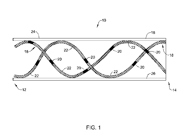
Figure 1 is an example stent including tubular members, radioactive elements
and spacers.
Figure 2 is an example radioactive element.
Figure 3 is an example radioactive strand having radioactive seeds and
spacers.
Figure 4 is an example tubular member including radioactive elements and
spacers.
Figure 5 is an example stent including tubular members, radioactive elements
and spacers.
Figure 6 is a cross section of an example radioactive stent and tubular
member.
Figure 7 is an example stent including tubular members, radioactive elements
and spacers.
Figure 8 is an example stent including tubular members, radioactive elements
and spacers.
Figure 9 is an example stent including an example shield positioned on the
outside of the stent.
Figure 10 is an example stent including an example shield positioned within a
strut of the stent.
While the disclosure is amenable to various modifications and alternative
forms, specifics thereof have been shown by way of example in the drawings and
will
be described in detail. It should be understood, however, that the intention
is not to
limit the invention to the particular embodiments described. On the contrary,
the
intention is to cover all modifications, equivalents, and alternatives falling
within the
spirit and scope of the disclosure.
DETAILED DESCRIPTION
For the following defined terms, these definitions shall be applied, unless a
different definition is given in the claims or elsewhere in this
specification.
5
CA 02994296 2018-01-30
WO 2017/031071
PCT/US2016/047064
All numeric values are herein assumed to be modified by the term "about",
whether or not explicitly indicated. The term "about" generally refers to a
range of
numbers that one of skill in the art would consider equivalent to the recited
value
(e.g., having the same function or result). In many instances, the terms
"about" may
include numbers that are rounded to the nearest significant figure.
The recitation of numerical ranges by endpoints includes all numbers within
that range (e.g. 1 to 5 includes 1, 1.5, 2, 2.75, 3, 3.80, 4, and 5).
As used in this specification and the appended claims, the singular forms "a",
"an", and "the" include plural referents unless the content clearly dictates
otherwise.
As used in this specification and the appended claims, the term "or" is
generally
employed in its sense including "and/or" unless the content clearly dictates
otherwise.
It is noted that references in the specification to "an embodiment", "some
embodiments", "other embodiments", etc., indicate that the embodiment
described
may include one or more particular features, structures, and/or
characteristics.
However, such recitations do not necessarily mean that all embodiments include
the
particular features, structures, and/or characteristics. Additionally, when
particular
features, structures, and/or characteristics are described in connection with
one
embodiment, it should be understood that such features, structures, and/or
characteristics may also be used connection with other embodiments whether or
not
explicitly described unless clearly stated to the contrary.
The following detailed description should be read with reference to the
drawings in which similar elements in different drawings are numbered the
same.
The drawings, which are not necessarily to scale, depict illustrative
embodiments and
are not intended to limit the scope of the disclosure.
Treatment of abnormal tissue growth (e.g. cancer) may be accomplished
through a variety of methodologies. For example, treatment of cancer may
include
the placement and deployment of a stent across the diseased tissue. However,
in some
instances stenting outcomes may be improved by combining one or more
conventional therapies. For example, combining stent placement with radiation
therapy may improve cancer treatment outcomes as compared to either stent or
radiation therapy alone. Therefore, it may be desirable to utilize materials
and/or
design a stent that combines traditional stenting with radiation therapy. Some
of the
6
CA 02994296 2018-01-30
WO 2017/031071
PCT/US2016/047064
examples and methods disclosed herein may include a stent that can delivery
radiation
therapy.
Stents disclosed herein may treat esophageal cancers. Additionally, the stent
may treat other forms of disease, including gastrointestinal, airway, urethra,
ureter,
cardiac, brain, breast, bladder, kyphoplasty and peripheral vascular disease,
for
example. Further, the stents disclosed herein may also be used in excisional
cavities
in solid and/or hollow organs.
Figure 1 shows an example radioactive stent system 10. Stent system 10 may
include a stent 16 and one or more tubular members 18. Tubular members 18 may
include one or more of a variety of radioactive elements 20. The radioactive
elements
may be separated from each other by one or more spacers 22. As will be
discussed
in greater detail below, tubular members 18 may extend longitudinally along
stent 16.
While Figure 1 shows tubular members 18 extending along the entire length of
stent
16, in other examples, the tubular members 18 may extend only along a part of
stent
15 16.
In some instances, stent 16 may be a self-expanding stent. Self-expanding
stent examples may include stents having one or more filaments combined to
form a
rigid and/or semi-rigid stent structure. For example, stent filaments may be
braided,
intertwined, interwoven, weaved, knitted or the like to form the stent
structure. Self-
20 expanding stents may be manufactured from a single, cylindrical tubular
laser-cut
Nitinol members.
In other instances stent 16 may be a balloon expandable stent. Balloon
expandable stents may be manufactured from a single, cylindrical tubular
member.
For example, in some instances, a cylindrical tubular member may be laser cut
to
form a balloon expandable stent.
Stent 16 in examples disclosed herein may be constructed from a variety of
materials. For example, stent 16 (e.g. self-expanding or balloon expandable)
may be
constructed from a metal (e.g., Nitinol). In other instances, stent 16 may be
constructed from a polymeric material (e.g., PET). In yet other instances,
stent 16
may be constructed from a combination of metallic and polymeric materials.
Additionally, stent 16 may include a bioabsorbable and/or biodegradable
material.
Stent 16 may include a covering. For example, stent 16 may be partially or
fully covered by an elastomeric or non-elastomeric material. Additionally,
stent 16
7
CA 02994296 2018-01-30
WO 2017/031071
PCT/US2016/047064
may be partially or fully covered by a polymeric material such as silicone or
ePTFE.
Further, the covering (e.g., polymer) may span the spaces (e.g., openings,
cells) in the
wall of stent 16. In some examples, the covering may be applied by spraying,
dipping, spinning or attaching a polymer sheet or tube the inner and/or outer
surface
of stent 16. In some examples, the covering may cover the stent filaments,
tubular
members 18 or both the stent filaments and the tubular members 18. Further, in
some
examples, the covering may cover a combination of one or more of the stent
filaments
and one or more of the tubular members 18. Additionally, in other examples the
stent
filaments and/or the tubular members 18 may extend partially or all the way
through
the covering.
In some examples, stent 16 may include anti-migration elements.
Anti-migration elements may include flares, fins, micro-patterns, controlled
ingrowth
features, quills, or the like. Anti-migration features may be beneficial in
controlling
the amount stent 16 moves during and/or after deployment in the lumen. In some
instances, the stent filaments and/or tubular members may include quills to
prevent
stent migration as described in U.S. Patent No. 8,715,334, the entirety of
which is
fully incorporated herein.
In some instances, it may be favorable to ensure that the radioactive seeds
are
positioned inside the stent in order to minimize the occurrence of "hot spots"
at the
tissues contacting the stent near the seeds. This can be accomplished by
positioning
the tubular members inside the stent or by ensuring that the seeds are
positioned
inside the stent when the tubular members are positioned over and under the
stent
filaments.
Figure 2 shows an example radioactive element 20. In some instances,
radioactive element 20 may be referred to as a "seed." The terms "radioactive
element" and "seed" may be used interchangeably throughout the remainder of
this
discussion. In general, seed 20 may be positioned adjacent a target site,
whereby seed
20 may release radioactive energy and/or material, thereby radioactively
treating the
target location.
Seed 20 may be generally shaped as shown in Figure 2. In other words, seed
20 may be an elongated cylinder having rounded ends. However, other shapes are
contemplated. For example, seed 20 may be rounded, ovular, rectangular,
triangular,
or the like.
8
CA 02994296 2018-01-30
WO 2017/031071
PCT/US2016/047064
Figure 2 shows the length of seed 20 depicted as dimension "X" and the
diameter of seed 20 as dimension "D." Depending on the particular therapeutic
application, different types of seeds may have different dimensions. For
example, in
some instances, seed 20 may have a length "X" of between 1 and 20 mm. In other
examples, seed 20 may have a length "X" between 2 and 10 mm, or between 3 and
8
mm. In some examples, seed 20 may have a length of about 5 mm.
Additionally, in some instances, seed 20 may have a diameter "D" of between
0.1 and 1.5 mm. In other examples, seed 20 may have a diameter "D" between 0.2
and 1 mm, or between 0.3 and 0.8 mm. In some examples, seed 20 may have a
diameter of about 0.5 mm.
Seed 20 may include a variety of radioactive materials and or combinations of
various materials. For example, seed 20 may include Iodine-125 (e.g. GE Oncura
THINSeedTm, IsoAid AdvantageTM by IsoAid, BestTM Iodine-125), Palladium-103
(e.g. CivaStringTM by CivaTech Technology, TheraseedTm by Theragenics, BestTM
Palladium-103), Cesium-131, Gold-198, Iridium-192 and/or Ytterbium-169 or any
other variations and/or derivatives thereof Further, seed 20 may include other
types
of radioactive material.
Additionally, seed 20 may include beta-emitting
radionuclides.
For at least some examples disclosed herein, it is contemplated that one or
more different radioactive elements 20 may be combined with one another to
target a
desired therapeutic outcome. For example, one or more of the radioactive
materials
disclosed above may be combined with one another to target a desired
therapeutic
outcome. Additionally, it is contemplated that different radioactive elements
20
having different radioactivity properties may be combined.
In some instances, one or more seeds 20 may combined with one or more
additional seeds 20 and/or one or more spacing elements to form an elongated
treatment member. For example, Figure 3 shows elongated treatment member 28
including seeds 20 and spacing elements 22. In some instances (including the
following discussion herein), treatment member 28 may be referred to as a
"strand."
The example shown in Figure 3 depicts a covering 30 surrounding the seeds
20 and spacers 22. In some instances, covering 30 may include a material
capable of
being placed over the combination of seeds 20 and/or spacers 22 to form a
continuous
strand 28. In some examples, covering 30 may include one or more of a variety
of
9
CA 02994296 2018-01-30
WO 2017/031071
PCT/US2016/047064
shrink tubing (e.g. a polymeric tubing capable of reducing in size upon the
application
or heat, for example). In other examples, the covering may include a
bioabsorbable
and/or biodegradable material. Additionally, in some instances seeds 20 and/or
spacers 22 may be connected to one another via a bioabsorbable connector. In
other
words, a combination of seeds 20 and/or spacers 22 may be "linked" to one
another
by a bioabsorbable and/or biodegradable material. In some instances, the
radioactive
strand may include a radioactive wire.
Seeds 20 and spacers 22 may be spaced and/or distributed in various patterns
and/or distributions along strand 28. The length of the spacers 22 (which may
to correspond to the space between any two seeds 20) may vary depending on
the
particular strand 28 configuration. Similarly, the length of a given seed 20
in
combination with a variety of lengths of given spacers 22 may vary depending
on a
particular strand 28 configuration. For example, Figure 3 depicts the length
of an
example seed 20 as "X" and the spacing distance between seeds as "Y." In some
example strands 28, the length "X" of the seed 20 may be between 2-8 mm, while
the
length "Y" of spacer 22 may be between 12-18 mm.
However, different lengths of the both seeds 20 and spacers 22 are
contemplated. Further, it can be appreciated that while some examples depicted
in the
figures disclosed herein show each seed 20 separated by a spacer 22, in some
stances
one or more seeds 20 may be placed directly adjacent one another. For example,
2, 3,
4, 5, 6, 7, 8, 9, 10, 15, 20 or more seeds 20 may be placed adjacent one
another in a
given strand 28. Further, adjacently placed seeds 20 may be separated from
other
adjacently placed seeds 20 by any length spacer 22.
Additionally, a given seed 20 and a given spacer 22 may have different
dimensions despite being positioned adjacent one another in a given strand 28.
For
example, a given strand 28 may have a variety of seeds 20 having a variety of
different lengths, diameters and materials. Similarly, a given strand 28 may
have a
variety of spacers 22 having a variety of different lengths, diameters and
materials.
Further, it is contemplated that a given strand may combine seeds 20 and
spacers 22
in a variety of different combinations, patterns, distributions, separations,
arrangements, or the like depending on the particular strand design required
for a
particular therapeutic application or user preference, for example.
CA 02994296 2018-01-30
WO 2017/031071
PCT/US2016/047064
As discussed above with respect to Figure 1, in some instances it may be
desirable to combine seeds 20 and/or spacers 22 with stent 16 to form a stent
system
having the structural elements of stent 16 combined with the therapeutic
properties
of a radioactive material (e.g. seeds 20). Further, in some instances it may
be
5 desirable to utilize a structural element that can both engage with the
stent structure
while also being capable of accepting (e.g. holding) the seeds 20.
Figure 4 shows an example tubular member 18 configured to accept, receive,
hold and/or contain radioactive material (e.g. seeds 20) and/or spacers 22.
While
tubular member 18 is shown as generally helical in shape in one embodiment
depicted
10 in Figure 4, this is not intended to be limited to a helical shape in
other instances. For
example, tubular member 18 may include a variety of shapes and/or
configurations
designed to engage and/or extend along stent 16.
As shown in Figure 4, tubular member 18 may include lumen 23 designed to
accommodate the placement of seeds 20, spacers 22 and/or a strand 28 within
lumen
23 of tubular member 18. The process of placing seeds 20, spacers 22 and/or
strands
28 inside tubular member 18 may be referred to as "loading" tubular member 18.
Lumen 23 may extend along the entire length of the tubular member 18 (e.g.
from a
proximal portion to a distal portion).
In some instances, loading the seeds 20, spacers 22 and/or strands 28 into
lumen 23 may be accomplished by pushing the seeds 20, spacers 22 and/or
strands 28
directly into lumen 23. In other instances, loading the seeds 20, spacers 22
and/or
strands 28 into lumen 23 may be accomplished by pulling the seeds 20, spacers
22
and/or strands 28 into lumen 23. For example, in some instances a strand 28
may
include a pull wire designed to be inserted into one end of a tubular member
18 (e.g.
through lumen 23) such that it can be seized at the opposite end of the
tubular member
18. The seeds 20, spacers 22 and/or strands 28 may then be pulled (e.g.
loaded) into
lumen 23 via the pull wire. In some instances, the pull wire may be rounded
and/or
coated with a friction-reducing coating to ease its movement through lumen 23.
Additionally, the pull wire may be constructed from a variety of materials.
For
example, the pull wire may be metallic or polymeric.
In some instances, it may be desirable to integrate tubular member 18 with
stent 16 prior to the loading of the radioactive material (e.g. seeds) into
lumen 23 of
tubular member 18. For example, in some examples, one or more tubular members
11
CA 02994296 2018-01-30
WO 2017/031071
PCT/US2016/047064
18 may be combined and/or engaged with stent 16 through a distinct
manufacturing
process during which radioactive material is not integrated with the stent
system (e.g.
loaded into lumen 23 of tubular members 18) until immediately before insertion
into
the vasculature.
Figure 5 shows example stent 16 engaged with one example tubular member
18. While Figure 5 shows one tubular member 18, it is contemplated more than
one
tubular member 18 may be engaged with stent 16. For example, 2, 3, 4, 5, 6, 7,
8, 9,
10, 15, 20 or 50 tubular members may be coupled with stent 16. Further, as
discussed
above, Figure 5 shows seeds 20, spacers 22 and/or strand 28 loaded into the
tubular
members 18. As shown, spacers 22 may be a variety of lengths, thereby creating
a
variety of patterns, arrangements and/or distributions of seeds 20.
In addition, Figure 5 shows stent 16 including one or more longitudinally
extending filaments 34. As discussed above, longitudinally extending filaments
34
may combine to form a self-expanding stent. For example, longitudinally
extending
filaments 34 may be braided, intertwined, interwoven, weaved, knitted or the
like to
form a self-expanding stent. Further, Figure 5 shows that tubular members 18
may be
integrated (e.g. intertwined) with the braided/weaved/knitted filaments 34 of
stent 16.
In other words, tubular members 18 may be one element in the overlapping
structure
that defines a braided stent 16. The detailed view 5A shows tubular member 18
(including seed 20 and spacer 22) braided with filaments 34. In other words,
the
tubular members 18 may be interwoven with the filaments 34 such that at some
cross-
over points the tubular member 18 is located radially outward of the filament
34
which the tubular member 18 crosses over, and at other cross-over points the
tubular
member 18 is located radially inward of the filament 34 which the tubular
member 18
crosses over. In some instances, such as those examples in which the stent
includes a
covering, the tubular members may extend through a portion or all the way
through
the covering.
While Figure 5 shows one tubular member 18 braided with one or more stent
filaments 34, it is contemplated that more than one tubular member 18 may be
utilized
to construct the braided structure. Further, in some instances tubular members
18
may be partially braided with one or more stent filaments 34.
In other examples, tubular members 18 may be intertwined, interwoven,
weaved, etc. within the structure (e.g. braided filaments, covering) of stent
16 without
12
CA 02994296 2018-01-30
WO 2017/031071
PCT/US2016/047064
being a component of the braided stent structure or the covering. For example,
tubular members 18 may be wound helically (clockwise, counterclockwise, or
both)
along the inside, outside or both the inside and outside surfaces of stent 16.
Tubular
members 18 may follow (e.g. extend alongside) one more filaments and/or a
covering
of stent 16. In other examples, the tubular members 18 may extend generally
straight
(e.g. longitudinally) along the inside, outside or both the inside and outside
surfaces of
stent 16.
Further, in any configuration the tubular members 18 may weave from an
inside surface of stent 16 to an outside surface of stent 16, then back to an
inside
surface of stent 16, and so on. In other words, tubular members 18 may extend
from a
position inside stent 16, through an opening in stent 16 to a position outside
stent 16,
back to a position inside stent 16 through another opening in stent 16, and so
on.
Figure 6 shows a cross sectional view along line 6-6 of Figure 5. In Figure 6,
tubular
member 18 may be positioned on the outer surface 24 of example stent 16.
Additionally, a portion of tubular member 18 may remain positioned "inside"
example stent 16. For example, example tubular member 18 may be positioned on
the
inner surface 26 of stent 16. The particular descriptions of the patterns for
which
tubular members may extend along stent 16 are not intended to be limiting,
rather, it
is contemplated that a variety and/or combinations of patterns may be utilized
that
couple stent 16 and tubular members 18. Additionally, as stated above tubular
members 18 may extend through stent openings as described above, while
additionally extending through a covering coupled to the stent 16.
In some instances, tubular members 18 may be coupled to stent 16 using
alternative and/or additional methods as those already described herein. For
example,
tubular members 18 may be sutured to individual stent filaments 34. The
sutures may
include longitudinal members that wrap around both a tubular member 18 and one
or
more stent filaments 34. The location of the sutures may be at a "cross-over"
point of
one or more filaments 34 and/or tubular members 18. In other words, a suture
may
extend around one or more filaments 34 and tubular members 18 in any
combination.
Further, the sutures may be positioned along the inner surface, the outer
surface or
both the inner and outer surfaces of stent 16. Additionally, the sutures may
be
constructed of a bioabsorbable and/or biodegradable material.
13
CA 02994296 2018-01-30
WO 2017/031071
PCT/US2016/047064
In other instances, tubular members 18 may be glued to individual stent
filaments 34 or to the covering of the stent. The glue may include a polymer
(e.g.,
silicone) that couples both a tubular member 18 and one or more stent
filaments 34
and/or the stent covering. The location of the glue points may occur at "cross-
over"
points of one or more filaments 34 and/or tubular members 18. In other words,
a
suture may extend around one or more filaments 34 and tubular members 18 in
any
combination.
For covered stents, the glue may extend along the entire length of the tubular
members. However, in some examples attaching the tubular members to the stent
may include utilizing a covering mandrel having helical grooves. The covering
mandrel may be used to insert the tubular members in the helical grooves. The
stent
may then be placed over the covering mandrel and the tubular members. The
stent
and the tubular members may then be covered with a polymer (e.g., silicone) by
a
dipping, spraying or other similar process.
In some instances, it may be desirable to load the seeds 20, spacers 22 and/or
strands 28 into the tubular members 18 after the tubular members 18 have been
integrated with stent 16 (e.g. via braiding, weaving, suturing, gluing, etc.
as described
above). In other instances, the seeds 20, spacers 22 and/or strands 28 may be
loaded
into the tubular members 18 after the stent has been implanted in the lumen.
This
may be accomplished through the use of an endoscope, for example.
Additionally, in some examples seeds 20, spacers and/or strands 28 may be
"replaced" within tubular members 18. In other words, it is contemplated that
a seed
20, spacer 22 and/or strand 28 may be individually removed and replaced by
another
seed 20, spacer 22 and/or strand 28. The replacement seed 20, spacer 22 and/or
strand
28 may be the same or a different material (e.g., radioactive material). In
some
instances, replacing the radioactive material may alter and/or change the
isotopes.
Replacing the radioactive source may be accomplished before or after the
medical
device (e.g. stent system 10) has been deployed at a target location. Examples
of
replacement of radioactive elements may include those discussed in U.S. Patent
Publication No. 20150190654, the entirety of which is incorporated herein.
As discussed above, the arrangement, pattern and/or distribution of seeds 20
may be varied along the length of stent 16. For example, by varying the
distances
between the seeds 20 (e.g. by varying the length of the spacers 22), the
overall
14
CA 02994296 2018-01-30
WO 2017/031071
PCT/US2016/047064
distribution of seeds 20 along both a circumferential and a longitudinal
direction can
be varied. The distribution of the tubular members 18 and, therefore, seeds
20, may
be symmetrical or asymmetrical along any direction of stent 16.
Creating variations in the pattern of seeds 20 may be accomplished by
changing both structural elements of the stent system and/or the spacing
between the
structural elements. For example, increasing the number of tubular members 18
engaged to a given stent 16 may result a more dense number of radioactive
seeds 20
for a given circumferential surface of stent 16. Furthermore, it can be
appreciated that
an increased density may result from increasing the total number of
radioactive seeds
in a given tubular member (e.g. via reducing the length of spacers 22, thereby
allowing the greater number of seeds loaded within a given tubular member 18).
In
some instances, the distribution of seeds along stent 16 may be such that the
tissue
surrounding stent 16 may receive a substantially uniform amount of radioactive
energy. In other instances, tubular members 18 may be asymmetrically arranged
about stent 16 such that a concentrated amount of radiation is delivered to a
specific
target tissue location. For example, an asymmetrically shaped tumor may
require an
asymmetrical distribution of tubular members 18 (and therefore, a non-uniform
distribution of radioactive seeds 20) configured to deliver a customized dose
of
radiation to the tissue of the asymmetrical tumor.
Further, it is contemplated that radioactive seeds 20 having different
radioactivity may be positioned along specific portions of stent 16. For
example,
seeds 20 having higher radioactivity may be positioned adjacent to the ends of
a stent
16 while seeds 20 having relatively lower radioactivity may be positioned away
from
the ends of stent 16 (e.g., along a central portion of stent 16). In other
examples,
seeds 20 having lower radioactivity may be positioned adjacent to the ends of
a stent
16 while seeds 20 having relatively higher radioactivity may be positioned
away from
the ends of stent 16 (e.g., along a central portion of stent 16). Thus, in
some instances
one or more seeds 20 having a first radioactivity and/or half-life may be
placed in a
tubular member 18 at a first end region of the tubular member 18, followed by
one or
more seeds 20 having a second radioactivity and/or half-life at a central
region of the
tubular member 18, followed by one or more seeds 20 having the first
radioactivity
and/or half-life (or a third radioactivity and/or half-life) at a second end
region of the
tubular member 18. The first radioactivity and/or half-life may be different
from the
CA 02994296 2018-01-30
WO 2017/031071
PCT/US2016/047064
second radioactivity and/or half-life and/or the third radioactivity and/or
half-life,
such as greater than or less than the second radioactivity and/or half-life
and/or the
third radioactivity and/or half-life. This arrangement may be repeated for
each
tubular member 18 arranged about stent 16, if desired. Specific (e.g., custom)
arrangement of seeds 20 along stent 16 may improve dose distribution.
Figure 7 shows an example stent system 10 similar to examples described
above (e.g. a stent including one or more tubular members, radioactive
elements
and/or spacers) viewed as a flat pattern (e.g. a stent system as described
herein cut
along its longitudinal axis and laid flat). As can be seen in Figure 7, four
tubular
members (labeled 1-4 in Figure 7) are engaged longitudinally along stent 16 in
a
helical arrangement. In some examples, the number of tubular members 18 in
stent
system may include more or less than four members 18. For example, in some
instances stent system 10 may include 1, 2, 3, 4, 5, 6, 7, 8, 9, 10, 15, 20 or
more
tubular members 18. In one example stent system 10, the number of tubular
members
may include six tubular members 18.
When viewed as a flat pattern, the four tubular members 18 are substantially
parallel and spaced approximately equidistant from one another. Further, if
the stent
shown in Figure 7 were viewed as a cylinder (e.g. as it would be when
delivered to a
target site in the lumen), tubular members 1-4 would wrap around stent 16 as
parallel
helices. It is understood that example stent system 10 may include more or
less than
four tubular members 18.
Figure 7 shows stent 16 having a proximal end 12. Further, each tubular
member 1-4 includes a seed 20 that is closer to proximal end 12 than any of
the other
seeds 20 in the respective tubular member 18. Moreover, Figure 7 shows that
for
each tubular member 1-4, the "most proximal" seed 20 may be "offset" from the
proximal end 12 of the stent 15 by a given distance. For example, the most
proximal
seed 20 of first tubular member 1 has a proximal offset defined as Xl.
Similarly, the
most proximal seed 20 of the second tubular member 2 has a proximal offset X2,
which is different from proximal offset X1 of most proximal seed 20 of first
tubular
member 1. As shown in Figure 7, the proximal offsets of each of third and
fourth
tubular members 3 and 4 are substantially equivalent to the proximal offsets
of first
and second tubular members 1 and 2, respectively. In some example, proximal
offset
X1 may 1 mm to 10 mm, or about 3 mm to 7 mm. In other examples, proximal
offset
16
CA 02994296 2018-01-30
WO 2017/031071
PCT/US2016/047064
X1 may be about 5 mm. In some examples, proximal offset X2 may be about 10 mm
to 30 mm, or about 15 mm to 25 mm, or about 18 to 22 mm. In other examples,
proximal offset X2 may be about 20 mm.
Further, the spacing between seeds 20 may be adjusted to vary the overall
pattern, distribution and/or density of the radioactive elements along stent
16. As
shown in Figure 7, the space between the first two seeds corresponding to
first tubular
member 1 (e.g. the length of an example spacer) is labeled "Z." In some
example,
distance "Z" may be about 5 mm to 40 mm, or about 10 mm to 30 mm, or about 15
mm to 25 mm, or about 18 mm to 22 mm. It can be appreciated that the lengths
of the
spacers and proximal offsets can be varied to achieve many different
variations in the
overall distribution of radioactive material along stent 16.
In some examples (such as the example described with respect to Figure 7),
one or more seeds 20 may overlap when viewed along the longitudinal axis. In
other
words, in some instances the distal (or proximal) end of a given seed 20 may
overlap
(longitudinally) with the proximal (or distal) end, respectively, of a
different seed 20.
As can be appreciated, longitudinal overlapping seeds 20 may occur in stent
designs
having a greater density, and hence, closer spaced seeds 20. In other
examples, the
distal/proximal end of a given seed 20 may not overlap (longitudinally) with
the
proximal/distal end, respectively, of any other seed 20.
In addition, tubular members 18 may be also be adjusted by varying the braid
angle and/or the degree at which a given tubular member "starts" with respect
to the
proximal end 12 of the stent. For a braided stent, it may be desirable to have
the
tubular members 18 at the same angle as the stent filaments in order to allow
for the
stent to be compressed in the delivery device, since a mismatch of the braid
angle may
prevent compression of the stent.
Further, in some instances a strand 28 may be constructed of seeds 20 and
spacers 22 alternating along the longitudinal axis of stent 16. In one
example, seeds
and spacers 20/22 may alternate every other along the length of stent 16 and
may
include seeds 20 from 2 to 8 mm in length and spacers from 12 to 18 mm in
length.
For example, one arrangement may have seeds 20 that are 5 mm in length
alternating
with spacers 22 that are 15 mm in length.
Further, in other examples, a plurality of tubular members 18 included in a
given stent system may have one "grouping" of tubular members that have a
proximal
17
CA 02994296 2018-01-30
WO 2017/031071
PCT/US2016/047064
offset and stent/spacer 20/22 arrangements that are different from a second
"grouping" of tubular members. For example, in some examples, a first grouping
of
tubular members 18 may include a proximal offset of approximately 2 to 7 mm
(e.g. 5
mm), while the second grouping of tubular members 18 may include a proximal
offset
of approximately 17 to 23 mm (e.g. 20 mm).
Figure 8 shows an alternative stent system 110. Stent system 110 may be
similar the stent system 10 discussed above with respect to Figure 1. For
example,
stent system 110 may include stent 116 and one or more tubular members 118.
Tubular members 118 may include one or more of a variety of radioactive seeds
120.
The seeds 120 may be separated from each other by one or more spacers 122. As
will
be discussed in greater detail below, tubular members 118 may extend
longitudinally
along stent 116.
In some instances, stent 116 may be a self-expanding stent. Further, as shown
in Figure 8, stent 116 may have a proximal portion 112, a distal portion 114
and an
intermediate portion 113. As shown, the proximal and distal portions 112/114
of stent
116 may be flared or enlarged relative to the intermediate portion 113, such
that the
proximal and distal portions 112/114 have a larger overall diameter than
intermediate
portion 113. In some instances, the shape of stent 116 may resemble that of a
"dog
bone," for example. Further, tubular members 118 may be connected to the
filaments
(not shown) of stent 116 by sutures and/or glue along the proximal, distal
and/or
intermediate portions 112/114/113. Further, in other instances the tubular
members
may be connected to stent 116 along the intermediate portion 113, while not
connected along either the proximal or distal portions 112/114.
In some instances, the examples discussed herein may further include one or
more "intensity modulation filters" (also referred to herein as "shields")
designed to
reduce and/or modulate the amount of radiation delivered by a radioactive seed
20.
For example, one or more shields may be placed between a radioactive seed 20
and
the vessel wall (e.g. targeted tissue) in order to modulate the amount of
radiation
reaching the tissue. Figure 9 shows shield 40 positioned between stent 16 and
tissue
41. As shown in Figure 9, in some instances one or more shields 40 may be
placed on
the outer surface of stent 16, thereby modulating the radiation delivered by
seeds 20
positioned on an inner surface of stent 16.
18
CA 02994296 2018-01-30
WO 2017/031071
PCT/US2016/047064
In other instances, one or more shields 40 may be positioned within at least a
portion of the wall of a strut of stent 16 and/or in the wall of a catheter
and/or tubular
member 18 holding radioactive seed 20. For example, Figure 10 shows an example
shield 40 positioned within at least a portion of the wall of a strut of stent
16. It can
be appreciated that shield 40 may be completely embedded within the example
stent
strut of stent 16. However, it is further contemplated that a portion of
shield 40 may
extend beyond an inner surface and/or outer surface of the example stent strut
of stent
16 and/or tubular member 18. In some instances, tubular members 18 may include
one or more shielded regions, including one or more shields 40 along the
length of
to tubular member 18. Shields 40 may be embedded in the wall of tubular
member 18,
inserted into lumen of tubular member 18, and/or positioned on an outer
peripheral
surface of tubular member 18, as desired.
Shields 40 may be constructed out of a variety of materials including metal,
metallic powder, polymer, etc. and in some instances may be placed inside a
polymer.
For example, the shields may include tungsten powder inside silicone. Further,
in
some instances, shield 40 may be of varying thickness. In some examples the
thickest
portion of shield 40 may include that portion of the shield 40 that is closest
to the
seed. Further, the thickness may taper (and become thinner) at the shield
extremities.
Additionally, in some instances shields 40 may include one or more openings or
holes
(not shown in Figure 9) extending fully or partially through the shield wall.
In some instances, shield 40 may be coupled to stent 16 and/or tubular
members 18 by a variety of attachment methods (e.g. gluing, etc.). For
example, in
some instances the shield 40 may include a metal plate coupled to stent 16
and/or
tubular members 18. In other instances, a shield may be applied by spraying,
painting
or similar methods. In some instances, a shield coupled to a tubular member 18
may
not cover the entire circumference and/or length of the tubular member.
Materials that may be used for the various components of stent system 10 and
the various examples disclosed herein may include those commonly associated
with
medical devices. For simplicity purposes, the following discussion makes
reference
to stent system 10. However, this is not intended to limit the devices and
methods
described herein, as the discussion may be applied to other similar systems
and/or
components of stent systems or devices disclosed herein.
19
CA 02994296 2018-01-30
WO 2017/031071
PCT/US2016/047064
It should be understood that this disclosure is, in many respects, only
illustrative. Changes may be made in details, particularly in matters of
shape, size,
and arrangement of steps without exceeding the scope of the disclosure. This
may
include, to the extent that it is appropriate, the use of any of the features
of one
example embodiment being used in other embodiments. The disclosure's scope is,
of
course, defined in the language in which the appended claims are expressed.