Note: Descriptions are shown in the official language in which they were submitted.
1
BAR ELEMENT
The invention relates to a bar element as a construction
element, wherein the bar element consists of a plurality of
strips, preferably produced from bamboo, and is configured as a
hollow element at least in certain sections, wherein the
interior of the hollow element is configured as a fillet, at
least in certain sections.
Such a bar element is already previously known from DE 20 2014
101 157 Ul.
Furthermore, it is previously known from WO 2013/157 771 Al to
produce a bicycle frame from bamboo, in which straight or bent
bamboo bars can be joined together by means of suitable
connection elements to produce a bicycle frame. Furthermore, it
is previously known from a final report regarding a BMBF [German
Federal Ministry of Education and Research] research project of
the Technical University of Dresden, "High-performance wooden
support structures - HHT - Development of composite designs in
wooden construction, able to withstand great stress, with fiber-
reinforced plastics, technical textiles, and shaped pressed
wood" to produce shaped wooden profiles and to process them in
such a manner, by means of targeted introduction of compressed
Date Recue/Date Received 2021-03-17
2
and non-compressed types of wood, that in this way, profiles
having changeable radii of curvature can be produced. It is
described as an alternative production method that strip cross-
sections can be connected with one another by means of joining
processes, even without any shaping process. In this regard, it
is considered disadvantageous that more or less complicated
dressing procedures performed on the strip segment are necessary
for every cross-section in order to achieve the desired
geometries. A further problem in this connection is what is
called the "memory effect," in other words that shaped wooden
profiles shaped in this way tend to resume their original shape
again after some time.
Proceeding from this state of the art, the invention is based on
the task of indicating a method for the production of bar
elements with which such bar elements can be produced, which
elements are subsequently suitable for use as a construction
element, also for the production of support structures, lattice
works, grid constructions or other three-dimensional bodies and
geometric bodies.
The task on which the invention is based is accomplished by
means of a bar element as described herein. Advantageous
Date Recue/Date Received 2021-03-17
3
embodiments of the invention are also described herein.
In detail, the task on which the invention is based is
accomplished in that the fillet formation of the bar element is
implemented by means of a plastic and/or resin that is
introduced into the bar elements, using a shaped body that can
be moved through the interior of the bar element. The advantage
as compared with solutions previously known from the state of
the art consists in that the corresponding bar elements are
produced from a natural and rapidly renewable raw material,
namely bamboo, wherein the production of this bar element takes
place by means of joining together strips having a defined
cross-section, to form a bar that possesses a defined interior
cross-section, since the inner configuration of the bar element
as a fillet is implemented in that a movable shaped body is
moved through the interior of the bar element, wherein
previously, the interior of the bar element was provided with an
introduced plastic and/or resin, which is brought into a defined
shape, namely the shape of a fillet, by means of the shaped
body, and subsequently hardens in this shape, which is in
accordance with its intended purpose. Alternatively, the
fillets formed in the interior of the bar element can also be
implemented by means of an inner tube that is pushed into the
Date Recue/Date Received 2021-03-17
4
interior of the bar element, and coated with an outer plastic
and/or resin mantle, preferably a fiber-reinforced mantle, on
the outside. After completion of the hardening process of the
materials that form the outer mantle, the inner tube can be
pulled out of the bar element, against the background of its
previous coating with a parting agent, leaving the outer mantle
that forms the fillet.
The configuration of the interior of the bar element as
described above brings about a reinforcement of the bar elements
produced in this manner, which accordingly possess greater
stability and, in particular, possess the required pressure
resistance and tensile strength as construction elements. A
further significant advantage of the solution according to the
invention consists in that in contrast to naturally grown
bamboo, a uniform tube cross-section is achieved over just about
any tube length, as is a precise wall thickness, by means of the
production of the bar elements as disclosed herein. Because the
individual bar elements can be produced with a defined cross-
section and a defined wall thickness, the bar elements produced
accordingly can be manufactured, used, and processed further
industrially. This is not possible in connection with naturally
grown bamboo tubes, since their diameter and wall thickness
changes over the length of the bamboo tubes, and furthermore,
Date Recue/Date Received 2021-03-17
5
the individual bamboo tubes also possess different diameters,
cross-sections, and wall thicknesses, in each instance, and this
accordingly makes connecting the natural bamboo tubes with one
another more difficult or impossible, even with different
connection elements and materials. The bar elements produced
from the aforementioned bamboo strips can be recycled, and,
depending on the adhesive connection used, can actually be
completely recyclable or ecologically biodegradable.
In a concrete embodiment, the shaped body that can be moved
through the interior of the bar element is a movable piston.
In the event of formation of the fillet using the inner tube,
the outer mantle introduced in connection with the inner tube,
which mantle remains in the bar element after the inner tube is
pulled out, can be provided with a fiber structure that is
optimally coordinated with the expected stress on the bar
elements. Thus, depending on the application, glass fibers,
carbon fibers or carbon fibers can be worked into the outer
mantle in the longitudinal or transverse direction, with the
formation of a woven lattice structure, in the simplest manner,
in that either the woven structure is wrapped around the inner
tube or that the longitudinal or transverse fibers are already
worked into the outer mantle.
Date Recue/Date Received 2021-03-17
6
The strips used for formation of the bar elements possess a
trapezoid cross-section, so that the individual strips can be
permanently connected with one another in the region of the
longitudinal edges of the strip, which are set at a slant, in
accordance with their intended use, to form a round bar element.
In a concrete embodiment, six or eight of the strips indicated
above are connected to form a closed bar element, by means of an
adhesive connection, which element subsequently has a hexagonal
or octagonal cross-section. In this connection, the strips are
connected with one another along their longitudinal edges, in
such a manner that they complement one another to form the
closed bar element described above.
In a further improved embodiment, the longitudinal edges of the
strips are configured to be planar to form the bar elements, so
that in this way, good adhesion behavior of the adjacent strips
in the region of these longitudinal edges for formation of an
adhesive connection is guaranteed.
The embodiment of the inner contour of the bar elements, by
means of the movable shaped body, can also be impressable in
certain sections, if necessary, in order to impress a defined
Date Recue/Date Received 2021-03-17
7
inner contour in the face-side end region of the bar elements,
in particular, for example a triangular or square or round inner
contour, which in turn can be helpful if multiple bar elements
are supposed to be connected with one another in the
longitudinal direction, following one another, for example by
means of the use of internally hollow bodies that can be pushed
into this inner contour with a corresponding outer contour.
In a concrete embodiment, an internally hollow body can be
pushed into the defined inner contour, in particular into the
face-side inner contour of a bar element, in such a manner that
this internally hollow body possesses an excess length as
compared with the one bar element, and a subsequent other bar
element can be set onto this excess length analogously, so that
two bar elements are connected with one another using the
internally hollow body.
In a further embodiment, two bar elements, in each instance, can
also be connected with one another by means of an angled-away or
cropped internally hollow body, wherein the angled-away or
cropped passage of the internally hollow body is disposed in the
intermediate region between the two bar elements, and thereby a
corner connection or curve connection between the two bar
elements involved in this connection is also produced.
Date Recue/Date Received 2021-03-17
8
In an even more improved embodiment, multiple bar elements can
also be joined together by means of one or more internally
hollow bodies, which in turn are provided with multiple
connector pieces, if necessary, in other words branch off
relative to these connector pieces, to produce polygonal
constructions, grid constructions, three-dimensional bodies,
geometric bodies or lattice works.
In a modified and even further improved embodiment, the bar
elements can also be connected with one another by means of
suitable internally hollow bodies, wherein the internally hollow
bodies used for a connection in this regard are provided with at
least one articulated connection, in each instance, in the
connection region that lies between the bar elements to be
connected. In this embodiment, articulated connections can be
produced within the scope of the invention, in other words
three-dimensional bodies that can be changed in terms of their
outer shape.
Furthermore, it is conceivable that separate connection
elements, each comprising at least two cuff sections that are
spaced apart from one another, can be set onto the excess
lengths of the internally hollow bodies disposed between the bar
Date Recue/Date Received 2021-03-17
9
elements that are to be connected, in such a manner that the
face-side end sections of the internally hollow bodies are held
with shape fit in these cuff sections, in each instance. The
use of the aforementioned cuff sections opens up an expanded
field of applications for the constructions produced by means of
the bar elements produced according to the invention, because
the corresponding cuff sections can be produced from a different
material from that of the bar elements or the internally hollow
bodies, and accordingly can be optimally adapted to the
respective requirements.
This furthermore holds true also for the internally hollow
bodies, articulated connections, connection elements and/or cuff
sections used in this regard. Thus, these intermediate pieces,
between the bar sections according to the invention, which are
used as connection elements in the broadest sense, can be
produced in cost-advantageous manner, in each instance, but with
precise dimensions and in adaptation to the respective
individual case, using a 3D printing method.
In this regard, the bar elements according to the invention do
not have to be produced as closed bar elements, but rather,
within the scope of the invention, half-round or other half-open
Date Recue/Date Received 2021-03-17
10
bar elements can be produced by means of the strips used for
production of the bar elements.
By means of the bar elements produced within the scope of the
invention, wall-like structures or honeycomb-like wall
structures can also be produced in that multiple of the bar
elements according to the invention are joined together with one
another along their outer contour, to produce composite bar
arrangements. This means, in concrete terms, that non only
framework constructions or lattice work constructions or grid
constructions can be produced with the bar elements according to
the invention, but also closed wall structures or room
structures can be produced, wherein it is possible, using the
aforementioned honeycomb structure, to fulfill the desired
strength limits, insulation properties or stability criteria, in
each instance, in simple manner, in that a composite bar
arrangement having the required wall thickness is produced, in
each instance. Thus, using the composite bar arrangements
according to the invention, it is also possible to produce
buildings or sections of buildings. In this regard, the
constructions according to the invention possess the advantage
that they are produced in resource-saving manner, from a natural
raw material or at least an extensively natural raw material,
and furthermore, they possess a lower weight and easier
Date Recue/Date Received 2021-03-17
11
workability as compared with conventional constructions made of
stone or other solids.
In an advantageous embodiment, not only the closed bar elements
but also open bar elements or closed half-bar elements can be
integrated into the aforementioned composite bar arrangements.
In a further advantageous embodiment, the composite bar
arrangement can have planks on one or both sides, or be produced
as a sandwich construction right from the start, wherein the
inner layer is formed by the composite bar arrangement explained
above, in each instance. In this case, the composite bar
arrangement can be supplemented with the interposition of
insulation materials and/or reinforcement materials, if
necessary.
The invention will be explained below, using one or more
exemplary embodiments.
The figures show:
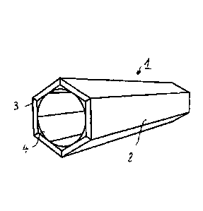
Fig. 1: a bar element having an octagonal outer
cross-section, in a perspective view,
Date Recue/Date Received 2021-03-17
12
Fig. 2: a bar element having a hexagonal outer
cross-section, having a fillet formation, in
a perspective view,
Fig. 3: a further bar element having an integrated,
coated inner tube as well as a round outer
cross-section, in a perspective view,
Fig. 4: a bar element having a round outer cross-
section, in an alternative embodiment, in a
perspective view,
Fig. 5: a bar element having an inner reinforcement,
in a perspective view,
Fig. 6: a bar element in a half-open embodiment,
Fig. 7 a) - c): a connection of two bar elements in
different connection stages, each in a
perspective view,
Fig. 8 a) - d): a right-angle connection of two bar elements
in different connection stages, each in a
perspective view,
Fig. 9 a) - c): a cross-connection of two bar elements in
different stages, each in a perspective
view,
Fig. 10: a honeycomb structure composed of bar
elements connected with one another, in a
perspective view, and
Date Recue/Date Received 2021-03-17
13
Fig. 11: a honeycomb structure composed of bar
elements connected with one another, in a
deviating embodiment, in a perspective view.
Figure 1, in a perspective view, shows a bar element 1 that
consists of a plurality of strips 2 produced from bamboo,
wherein the strips 2 each possess a trapezoid cross-section. In
this regard, the strips 2 are connected with one another in the
region of their longitudinal edges 3, by means of a suitable
adhesive connection, in each instance. After the strips 2 are
produced using an industrial cutting method, it is ensured that
the longitudinal edges 3 are configured in planar manner, to
form a strong connection, and furthermore so that the bar
elements 1 produced by means of the method according to the
invention are provided with reproducible cross-sections, in each
instance.
In a further work step, the bar elements 1 according to Figure 2
can be coated with a plastic and/or resin on their inner walls,
and in a further work step, a movable piston having a round
outer cross-section can be guided through the bar element 1, at
least in certain sections, with the result that a round inner
cross-section 4 is impressed on the bar element 1, in other
words a fillet is formed, which is also strong after the
Date Recue/Date Received 2021-03-17
14
laminate material that was introduced has hardened.
Accordingly, the bar elements 1 according to Figure 2 also
possess a reproducible inner cross-section with clearly defined
dimensions.
According to the representation in Figure 3, the polygonal bar
elements according to the representations in Figures 1 and 2 can
also be worked in such a manner that bar elements 1 having a
round outer cross-section 5 are produced from the polygonal
ones. This can be implemented in that the polygonal pipes are
lathed on their outside, until the desired round outer cross-
section 5 has formed. The problem that exists in this
connection, that of a reduced wall thickness due to the outer
cross-section of the bar element 1 being lathed away on the
outside, can be corrected, according to the representation in
Figure 3, in that a round inner tube, which is provided with an
outer mantle, is introduced into the interior of the bar element
1. The outer mantle is applied to the inner tube from the
outside, with the interposition of a parting layer, and usually
consists of resin or plastic or of a composite of these
materials, wherein in addition, glass fibers, carbon fibers or
carbon fibers are worked into this outer mantle for further
reinforcement, in a manner that is not shown in any detail.
These fibers can be introduced into the outer mantle in simple
Date Recue/Date Received 2021-03-17
15
manner, in the form of a woven mat that is wound around the
inner tube, but also worked into the outer mantle as individual
fibers, in the longitudinal and/or transverse direction. After
the outer mantle has hardened, the inner tube, due to the
parting layer that lies in between, can simply be pulled out of
the bar element 1, which then possess a round inner cross-
section, and, due to the integrated fiber arrangement, possesses
greater rigidity, by means of which the loss in rigidity that
was brought about by lathing off the outer cross-section of the
bar element is compensated or overcompensated.
Alternatively, according to the representation in Figure 4, the
outer surface of the outer cross-section of the bar element 1
can be reinforced by means of application of a further bamboo
strip 6, in each instance, and the bar element 1 can be lathed
off only then, until once again, a round outer cross-section 5
is achieved. This occurs with the difference that the wall
thickness of the bar element 1 achieved in this way is clearly
reinforced as compared with the embodiment in Figure 3.
The bar elements 1 according to the representations in Figures
1-4 can be reinforced and stiffened by means of suitable inner
reinforcements, if necessary, wherein according to the
representation in Figure 5, a triangular inner tube 7 was used,
Date Recue/Date Received 2021-03-17
16
which is preferably also produced from bamboo and is produced,
analogously, in that the bamboo strips for production of the
inner tube 7 are connected with one another in the region of
their longitudinal edges 3' - for example by means of a suitable
adhesive connection. This inner tube 7 is introduced into the
bar element 1 to reinforce it, in the sense of a press fit, and
accordingly brings about greater strength of the bar element 1.
Alternatively or in addition, the interior of the bar element 1
can also be filled with a filling compound, for example filled
with foam, wherein in this connection, either only the interior
of the inner tube 7 or the entire interior of the bar element 1
can be filled with compound or filled with foam.
Figure 6, also in a perspective view, shows a bar element that
has not yet been completed.
According to the perspective representation in Figure 7,
multiple bar elements 1 can be joined together by means of
suitable connection elements. According to the representation
in Figure 7, internally hollow bodies 10, which can but do not
have to be bar elements 1, 1' according to the invention, once
again, can be pushed into the defined inner cross-section of a
bar element 1, with shape fit, specifically in such a manner
that the internally hollow body 10 according to the
Date Recue/Date Received 2021-03-17
17
representation in Figure 7 b) forms an excess length 11 as
compared with the one bar element 1, before the other bar
element 1' is then set onto the internally hollow body 10, and
thereby a connection of the two bar elements 1, 1' is produced
according to Figure 7 c).
In this regard, the internally hollow bodies 10 can be shaped
more or less in any desired manner to produce the connection
between two bar elements 1, 1', in other words as an angled
element or as a curved element, for example, so that angular or
curved connections between multiple bar elements 1, 1' according
to the representation in Figure 8 are also conceivable. In this
regard, curved connections can be implemented only when using
special connection elements, in any case elements not produced
from bamboo, for example produced by die-casting or 3D printing.
In detail, Figure 8 shows the different connection stages
between two bar elements 1, 1' that participate in the
connection, in a perspective representation, in each instance,
which elements can be connected with one another by means of an
internally hollow body 10 according to the exploded
representation or in the representation before the formation of
the connection according to Figure 8 a), which body is formed,
in this case, as an angled element, with the formation of a
right angle.
Date Recue/Date Received 2021-03-17
18
In this regard, the internally hollow body 10 is introduced into
the bar element 1, at least in certain sections, according to
the representation in Figure 8 b), before the other bar element
1' is then also set onto the internally hollow body 10, at least
in part, according to Figure 8 c), and finally a closed
connection between the two bar elements 1, 1' is produced by
means of completely setting on the two bar elements 1, 1' that
participate in the connection, in such a manner that ultimately,
an angled element is produced by means of the configuration of
the connection.
Any desired other constructions can also be produced by means of
the selection of suitable connection elements. Thus, Figure 9
shows the individual steps of the formation of a cross-
connection, in that in detail, four bar elements 1 are produced,
using a central cross-connector 12, in that the bar elements 1
are set onto the individual connection pieces of the cross-
connector 12, in each instance.
More or less any desired lattice works, grid constructions,
frameworks, three-dimensional bodies or, in the case of
connection elements having integrated articulations, also
Date Recue/Date Received 2021-03-17
19
spatially changeable bodies or articulated connections can be
produced by means of these and comparable constructions.
In connection with the formation of more complex constructions,
expansive constructions such as frameworks or three-dimensional
bodies, it has proven itself if the individual connection
elements are provided with cuffs for face-side accommodation of
the bar elements 1 according to the invention, so that these are
stabilized in their end region, and possible breakout of the bar
element 1 in the end region is prevented or the connection is
only insignificantly impaired by it. Such connections have
proven to be strong also in connection with simple
constructions.
Furthermore, wall structures of any desired shape and wall
thickness can be produced using the bar elements 1, 1' according
to the invention, which can be joined together by means of
suitable adhesive connections, to produce a composite
arrangement or honeycomb arrangement 13 according to Figure 10.
In this regard, the individual bar elements 1, 1' for forming
the wall structure, can once again be provided with
reinforcements, if necessary, as explained above, or can be
filled with reinforcement material or with insulation material,
if necessary.
Date Recue/Date Received 2021-03-17
20
In this regard, fundamentally closed bar elements 1, 1' do not
necessarily have to be inserted into the honeycomb structure 13
according to the representation in Figure 11. Instead,
alternatively, open bar elements or closed half-bars can also
be integrated, for example in order to be able to produce a
defined wall end.
The honeycomb arrangements 13 shown in Figures 10 and 11 are
usually advantageously provided with planking on one or both
sides, particularly in the construction sector, or produced
using sandwich construction right from the start, with
interposition of the honeycomb arrangement. In this regard,
this sandwich construction can already take place with the
interposition of insulating materials or insulation materials,
if applicable leaving out any channels required for
installation.
Date Recue/Date Received 2021-03-17
21
REFERENCE SYMBOL LIST
1, 1' bar element
2 strip
3, 3' longitudinal edge
4 round inner cross-section
round outer cross-section
6 further bamboo strip
7 triangle inner tube
internally hollow body
11 excess length
12 cross-connector
13 honeycomb arrangement
Date Recue/Date Received 2021-03-17