Note: Descriptions are shown in the official language in which they were submitted.
DESCRIPTION
METHOD FOR WELDING AUSTENITIC STAINLESS STEEL SHEETS
TECHNICAL FIELD
[0001]
The present invention relates to a method for welding austenitic stainless
steel
sheets, which method welds overlapped austenitic stainless steel sheets.
BACKGROUND ART
[0002]
In recent years exhaust gases have been strictly regulated from a standpoint
of
environmental issues, and there is a tendency to raise the temperature of
exhaust gases to
further improve fuel efficiency and engine combustion efficiency.
[0003]
In order that the capacity for purifying exhaust gases at the time of engine
staffing
will become more efficient, a dual wall exhaust manifold including an inner
pipe and an
outer pipe and having a void between the inner pipe and outer pipe can be
loaded (see e.g.
PTL 1 to 3).
[0004]
In this type of dual wall exhaust manifold, the inner pipe tends to be thinner
than
a pipe in a single wall exhaust manifold.
[0005]
Therefore, ferritic stainless steel, which has a small coefficient of thermal
expansion, is usually used for a single wall exhaust manifold; however,
austenitic stainless
steel, which has better workability than ferritic stainless steel, is used for
the inner pipe in
a dual wall exhaust manifold.
CITATION LIST
Patent Literature
[0006]
1
CA 2995056 2018-04-17
PTL1: Japanese Laid-open Patent Publication No. 11-93654
PTL2: Japanese Laid-open Patent Publication No. 8-334017
PTL3: Japanese Laid-open Patent Publication No. 8-334018
SUMMARY OF INVENTION
Technical Problem
[0007]
The inner pipe and outer pipe in a dual wall exhaust manifold are often
produced
by overlapping press-molded pipe parts and carrying out fillet weld by arc
welding such as
MIG welding.
[0008]
However, since the inner pipe in a dual wall exhaust manifold is thinner than
a
pipe in a common single wall exhaust manifold, it is very difficult to control
heat input in
welding and there is a problem in that welding defects such as hot cracking
and ductility-
dip cracking easily occur particularly in a weld joint region.
[0009]
The present invention was made in view of such points, and an object thereof
is to
provide a method for welding austenitic stainless steel sheets, in which
welding defects do
not easily occur.
Solution to Problem
[0010]
According to an aspect the invention relates to a method for welding
austenitic
stainless steel sheets, comprising the step of:
-overlapping austenitic stainless steel sheets and obtaining an overlapped
portion;
-welding the overlapped portion by arc welding,
each of said austenitic stainless steel sheets having a sheet thickness of 0.6
mm to 1.0 mm,
and containing C: 0.08 mass% or less, Si: 1.5 mass% to 4.0 mass%, Mn: 2.0
mass% or less,
P: 0.04 mass% or less, S: 0.01 mass% or less, Cr: 16.0 mass% to 22.0 mass%,
Ni: 10.0
mass% to 14.0 mass%, N: 0.08 mass% or less, and at least one of Nb and Ti in
an amount
2
CA 2995056 2018-04-17
of 1.0 mass% or less in total, with the rest including Fe and inevitable
impurities, and
-cooling from 1200 C to 900 C at a cooling rate of 110 C/see or higher a back
side of a deposited portion, which is a site with the highest temperature at
the time of
welding on a back side of a welded surface.
[0011]
In one embodiment the austenitic stainless steel sheets further contain at
least
one of Al, Zr and V in an amount of 1.0 mass% or less in total.
[0012]
In another embodiment the austenitic stainless steel sheets further contain at
least
one of Mo and Cu in an amount of 4.0 mass% or less in total.
[0013]
In a further embodiment the austenitic stainless steel sheets contains B in an
amount of 0.01 mass% or less.
[0014]
In a further embodiment, the length of an overlap space in a weld joint region
when welding the overlapped portion is 2.5 mm or more. In other words, in that
embodiment the overlapped portion has a length of 2.5 mm or more.
Advantageous Effects of Invention
[0015]
According to the present invention, the back side of a deposited portion,
which is
a site with the highest temperature at the time of welding on the back side of
the welded
surface, is cooled from 1200 C to 900 C at a cooling rate of 110 C/sec or
higher, and thus
heat generated at the time of welding can be transferred and the occurrence of
welding
defects can be prevented.
BRIEF DESCRIPTION OF DRAWINGS
[0016]
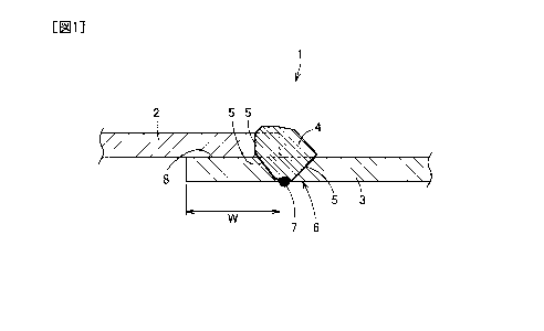
[Fig. 1]
3
CA 2995056 2018-04-17
Fig. 1 is a cross-section view schematically showing a weld joint region
according
to an embodiment of the present invention.
[Fig. 2]
Fig. 2 is a cross-section view schematically showing a deformed example of the
weld joint region described above.
[Fig. 3]
Fig. 3 is a graph showing a relationship between a cooling rate and a crack
occurrence rate in Examples and Comparative Examples.
DESCRIPTION OF EMBODIMENTS
[0017]
The structure of an embodiment of the present invention will now be described
in
detail.
[0018]
A dual wall exhaust manifold includes an outer pipe, and an inner pipe
arranged
via a gap on the inside of the outer pipe. The outer pipe and inner pipe are
each subjected
to MIG welding in a weld joint region 1 shown in Fig. 1 using a weld rod such
as a weld
wire, and are fixed with a hollow heat-insulting layer arranged between the
outer pipe and
the inner pipe.
[0019]
In addition, by such welding, the weld joint region 1 forms a structure having
a
pipe base material portion 2, a pipe base material portion 3, a deposited
portion 4 in which
the pipe base material portions 2, 3 are deposited, and a bond portion 5 which
is a boundary
between the pipe base material portions 2, 3 and the deposited portion 4. It
should be
noted that the dashed line in Fig. 1 shows a state in which the pipe base
material portions
2, 3 before deposition are set.
[0020]
The inner pipe is thinner than the outer pipe and it is very difficult to
control heat
input in welding, and thus it is important not to easily cause welding defects
such as hot
cracking and ductility-dip cracking.
4
CA 2995056 2018-04-17
[0021]
Therefore, an austenitic stainless steel sheet with a sheet thickness of 0.6
mm to
1.0 mm, which has better workability than ferritic stainless steel, is used
for the inner pipe.
In addition, the components of austenitic stainless steel for the inner pipe
are specifically
designed as described below.
[0022]
The base material components for the inner pipe (austenitic stainless steel)
contain
0.08 mass% or less of C (carbon), 1.5 mass% to 4.0 mass% of Si (silicon), 2.0
mass% or
less of Mn (manganese), 0.04 mass% or less of P (phosphorus), 0.01 mass% or
less of S
(sulfur), 16.0 mass% to 22.0 mass% of Cr (chromium). 10.0 mass% to 14.0 mass%
of Ni
(nickel), and 0.08 mass% or less of N (nitrogen), and contain at least one of
Nb (niobium)
and Ti (titanium) in an amount of 1.0 mass% or less in total, and the rest
includes Fe (iron)
and inevitable impurities.
[0023]
It should be noted that austenitic stainless steel may have a structure
containing at
least one of Al (aluminum), Zr (zirconium) and V (vanadium) in an amount of
1.0 mass%
or less in total as needed.
[0024]
In addition, austenitic stainless steel may have a structure containing at
least one
of Mo (molybdenum) and Cu (copper) in an amount of 4.0 mass% or less in total
as needed.
[0025]
Furthermore, austenitic stainless steel may have a structure containing B
(boron)
in an amount of 0.01 mass% or less as needed.
[0026]
C is effective in improving the high-temperature strength of austenitic
stainless
steel; however, when C is excessively contained, above 0.08 mass%, there is a
possibility
that Cr carbide will be formed during use to deteriorate toughness and
moreover there is a
possibility that the amount of Cr solid solution effective in improving high-
temperature
oxidation resistance will be reduced. Therefore, the C content is 0.08 mass%
or less (there
are not cases where C is not contained).
CA 2995056 2018-04-17
[0027]
Si is very effective in improving high temperature oxidation characteristics,
and
when Si is contained in a base material in an amount of 1.5 mass% or more, a
Si
concentrated film is formed on the inside of Cr oxide at a temperature range
of 850 to
900 C to improve scale peeling resistance. However, when Si is excessively
contained in
a base material, above 4.0 mass%, there is a possibility that a embrittlement
sensitivity will
increase to cause a embrittlement during use. Therefore, the Si content is 1.5
mass% or
more and 4.0 mass% or less, preferably 3.0 mass% or more and 4.0 mass% or
less.
[0028]
Mn is an austenite phase stabilizing element and mainly shows the action of
adjusting the balance of the 6 phase; however, when Mn is excessively
contained, above
2.0 mass%, there is a possibility that high-temperature oxidation resistance
will be reduced.
Therefore, the Mn content is 2.0 mass% or less (there are not cases where Mn
is not
contained).
[0029]
When P is contained in an amount of above 0.04 mass%, there is a possibility
that
the hot workability of austenitic stainless steel will be reduced, and thus it
is preferred that
the content be reduced as much as possible. Therefore, the P content is 0.04
mass% or
less.
[0030]
When S is contained in an amount of above 0.01 mass%, there is a possibility
that
the hot workability of austenitic stainless steel will be reduced like P, and
thus it is preferred
that the content be reduced as much as possible. Therefore, the S content is
0.01 mass%
or less.
[0031]
Cr suppresses scale formation at high temperature and is an element effective
in
improving high temperature oxidation characteristics, and it is required to
contain 16.0
mass% or more of Cr to show such action. However, when Cr is excessively
contained,
above 22.0 mass%, there is a possibility that a embrittlement will be caused.
Therefore,
the Cr content is 16.0 mass% or more and 22.0 mass% or less.
6
CA 2995056 2018-04-17
[0032]
Ni is an austenite phase stabilizing element and is mainly contained to adjust
the
balance of the 6 phase; however, it is required to contain 10.0 mass% or more
of Ni to show
such action. However, when Ni is excessively contained, an increase in costs
will be
caused and thus the upper limit of the Ni content is 14.0 mass%. Therefore,
the Ni content
is 10.0 mass% or more and 14.0 mass% or less.
[0033]
N is an element to improve high-temperature strength by solid solution
strengthening; however, when N is excessively contained, above 0.08 mass%,
there is a
possibility that toughness will be reduced due to the formation of Cr nitride.
Therefore,
the N content is 0.08 mass% or less (there are not cases where N is not
contained).
[0034]
Nb and Ti are elements which are bound to C and N to improve high-temperature
strength; however, when Nb and Ti are excessively contained, there is a
possibility that a
low melting point will be caused. Therefore, when Nb and Ti are contained to
improve
high-temperature strength, at least one of Nb and Ti is contained in an amount
of 1.0 mass%
or less in total.
[0035]
Al is a potent ferrite forming element and is effective for stabilization of
the 6
phase. In addition, Zr and V are elements which are bound to C and N to
improve high-
temperature strength. However, when Al, Zr and V are excessively contained,
there is a
possibility that a low melting point will be caused. Therefore, when Al, Zr
and V are
contained to improve high-temperature strength, it is preferred that at least
one of Al, Zr
and V be contained in an amount of 1.0 mass% or less in total.
[0036]
Mo is a ferrite forming element and is effective in improving high-temperature
strength; however, when Mo is excessively contained, there is a possibility
that a
embrittlement will be caused and toughness will be reduced. In addition, Cu is
an
austenite forming element and is useful in improving high-temperature
strength; however,
when Cu is excessively contained, there is possibility that high-temperature
oxidation
7
CA 2995056 2018-04-17
resistance will be reduced. Therefore, when Mo and Cu are contained to improve
high-
temperature strength, it is preferred that at least one of Mo and Cu be
contained in an
amount of 4.0 mass% or less in total.
[0037]
B is effective in improving the grain boundary strength of a weld joint region
to
improve heat resistance; however, when B is contained in a large amount, there
is a
possibility that hot workability will be reduced. Therefore, when B is
contained to
improve heat resistance, it is preferred that the B content be 0.01 mass% or
less.
[0038]
A welding method for welding the above austenitic stainless steel sheet will
now
be described.
[0039]
When welding inner pipes, MIG welding is carried out with parts of the inner
pipes overlapped each other.
[0040]
It should be noted that the welding conditions of MIG welding, the type of
core
wire and the flow rate of shielding gas for example can be suitably set and
selected. Inert
gases such as argon and nitrogen are used as types of shielding gas, and it is
preferred that
the oxygen concentration in an inert gas be 5.0 vol% or less from a standpoint
of the
prevention of oxide incorporation in a weld region.
[0041]
In order to prevent the occurrence of welding defects such as welding hot
cracking
in MIG welding, heat transfer is important in which heat generated at the time
of welding
is promptly transferred to another site by cooling after welding.
[0042]
In order to effectively prevent the occurrence of welding defects by promptly
transferring heat after welding, it is effective to restrict a cooling rate
for the back side of
the welded surface 6 opposite to the welded surface in a weld joint region I.
[0043]
Specifically, the back side of a deposited portion 7, which is a site with the
highest
8
CA 2995056 2018-04-17
temperature on the back side of the welded surface 6, is cooled from 1200 C to
900 C at a
cooling rate of 110 C/sec or higher after welding.
[0044]
As a method for increasing the cooling rate after welding and setting the
cooling
rate to 110 C/sec or higher, for example a method in which heat input itself
in welding is
reduced within a range acceptable in terms of product properties, a method in
which a back
plate of Cu and the like is put on the back side of the welded surface 6 to
promote heat
transfer, a method in which the flow rate of back-shielding gas is adjusted, a
method in
which shielding gas is directly sprayed to the back side of the welded surface
6 and the like
can be suitably carried out.
[0045]
Here, a site where heat is least likely to transfer at the time of welding is
an
overlapped portion 8 where steel sheets are overlapped each other. Therefore,
a structure
in which the length of an overlap space W in the overlapped portion 8 is 2.5
mm or more
is preferred to enlarge the volume of the overlapped portion 8 and promote
thermal
conduction (heat transfer), and the length of the overlap space W is more
preferably 4.0
mm or more.
[0046]
Then, according to the above method for welding austenitie stainless steel
sheets,
a cooling rate when cooling the back side of a deposited portion 7, which is a
site with the
highest temperature at the time of welding on the back side of the welded
surface 6, from
1200 C to 900 C is 110 C/sec or higher, and thus heat generated at the time of
welding on
the back side of the welded surface 6, where welding defects easily occur, can
be promptly
transferred to another site. Therefore, the influence due to heat generated at
the time of
welding, which causes welding defects, can be suppressed and the occurrence of
welding
defects such as hot cracking and ductility-dip cracking in HAZ (heat-affected
zone) can be
prevented.
[0047]
In addition, when the length of an overlap space W when welding the overlapped
portion 8 is 2.5 mm or more, the volume of the overlapped portion 8 can be
enlarged to
9
CA 2995056 2018-04-17
promote thermal conduction (heat transfer) and a cooling rate can be raised,
and thus the
occurrence of welding defects can be effectively prevented. Furthermore, when
the
length of an overlap space W is 4.0 mm or more, the occurrence of welding
defects can be
more effectively prevented.
[0048]
It should be noted that MIG welding is used as arc welding in the above method
for welding austenitic stainless steel sheets; however, for example, TIG
welding, MAG
welding, shielded metal arc welding and the like can be also applied.
[0049]
In addition, the overlapped portion 8 is subjected to fillet weld in the above
method
for welding austenitic stainless steel sheets, and welding can be carried out
around the
middle part of the overlapped portion 8, for example, like a deformed example
shown in
Fig. 2.
[0050]
Furthermore, the above method for welding austenitic stainless steel sheets
can be
applied in both when welding austenitic stainless steel sheets each other and
when welding
an austenitic stainless steel sheet and another material.
Examples
[0051]
Examples and Comparative Examples will now be described.
[0052]
Austenitic stainless steel having components shown in Table 1 was melted to
obtain a cold-rolled annealed sheet with a sheet thickness of 0.8 mm. In
addition, a test
piece in the form of sheet of 100 x 200 mm was cut from each cold-rolled
annealed sheet.
[0053]
[Table 1]
St
NC NA MC Categ
ee C S i P S N Ti Zr V
i r b 1 o u ory
1
CA 2995056 2018-04-17
ty
pe
o.
0. 2. 0. 0. 1 1 0. 0.
0.0
1 0 0 7 02 3. 9. 0 1
008
5 1 7 5 1 3 4 2
0. 2. 0. 0. 1 1 0. 0.
0.0
2 0 5 7 02 3. 9. 0 1
007
4 5 4 9 9 5 3 1
0. 3. 0. 0. 1 1 0. 0.
0.0
3 0 2 8 02 3. 9. 0 1
008
4 6 2 6 3 2 3 0
0. 3. 1. 0. 1 1 0. 0.
0.0
4 0 8 2 02 2. 7. 0 1
005
4 5 3 2 9 8 4 0
Exam
0. 3. 0. 0. 1 1 0. 0.
0.0 ples
5 0 3 8 02 3. 8. 0 1
009
4 2 8 5 4 8 4 5
0. 3. 1. 0. 1 1 0. 0.
0.0
6 0 3 2 02 3. 8. 0 2
009
5 5 2 2 9 5 4 3
0. 3. 0. 0. 1 1 0. 0.
0.0
7 0 3 8 02 3. 8. 0 3
008
4 3 8 9 5 8 4 1
0. 3. 0. 0. 1 1 0. 0.
0.0 2.
8 0 2 9 02 3. 8. 0 0
008 5
4 9 2 9 4 5 4 8
9 0. 3. 0. 0. 0.0 1 1 0. 2
11
CA 2995056 2018-04-17
0 2 8 02 009 3. 8. 0
4 5 5 3 4 6 4 1
0. 3. 1. 0. 1 1 0. 0.
0.0
10 0 8 4 02 3. 7. 0 00
009
4 9 2 2 2 2 5 3
0. 4. 0, 0. 1 1 0. 0.
0.0
11 0 1 8 04 5. 6. 0 1
010
4 1 9 2 5 3 4 1
0. 4. 0. 0. 1 1 0. 0.
0.0
12 0 2 9 02 7. 7. 0 3
010
4 5 9 9 2 1 4 0
Comp
0. 3. 0. 0. 1 1 0.
0.0 arative
13 0 1 7 05 4. 6. 0
029 Exam
4 9 8 5 2 9 4
pies
0. 1. 0. 0. 1 1 0.
0.0
14 0 3 6 08 2. 7. 0
065
4 9 7 3 8 9 4
0. 5. 1. 0. 1 1 0. 0.
0.0
15 0 0 8 02 6. 8. 0 1
011
5 1 5 8 9 1 4 0
[0054]
Two test pieces of each steel type were overlapped and subjected to MIG
welding
under conditions of a current of 120 A, a voltage of 14.4 V, a core wire 308
(fl 1.2 mm),
Ar + 5 vol% 02 as a shielding gas, and a shielding gas flow rate of 10 L/min,
and Ar was
then directly sprayed as a back-shielding gas to the back side of the welded
surface to cool
the back side of a deposited portion. The cooling rate was controlled by
adjusting the
flow rate of the back-shielding gas.
[0055]
12
CA 2995056 2018-04-17
In each steel type, 5 samples were produced and the number of evaluation was
5.
One in which cracking occurred on the back side of a deposited portion was
evaluated as
cracking and the crack occurrence rate was calculated.
[0056]
In each steel type, the overlap space, the cooling rate when cooling the back
side
of a deposited portion from 1200 C to 900 C and the crack occurrence rate are
shown in
Table 2 and a relationship between the cooling rate and the crack occurrence
rate is shown
in Fig. 3. In Fig. 3, o shows a case where cracking did not occur and = shows
a case
where cracking occurred.
[0057]
[Table 2]
Crack
Overlap space Cooling rate
Steel type No. occurrence rate Category
(mm) ( C/sec)
(%)
1 3.0 111.5 0
2 3.5 112.4 0
3 5.5 116.9 0
4 6.0 119.5 0
4.0 114.2 0
Examples
6 5.5 116.3 0
7 5.0 115.9 0
8 4.0 113.9 0
9 5.0 114.7 0
4.5 115.6 0
11 2.5 102.1 40
12 1.5 95.3 80
Comparative
13 2.0 100.9 60
Examples
14 2.5 103.8 60
3.0 105.8 20
13
CA 2995056 2018-04-17
[0058]
As shown in Table 2 and Fig. 3, in all Examples, steel type Nos. 1 to 10, in
which
the cooling rate when cooling the back side of a deposited portion from 1200 C
to 900 C
was 110 C/see or higher, cracking did not occur on the back side of a
deposited portion
and weldability was excellent.
[0059]
On the other hand, in all Comparative Examples, steel type Nos. 11 to 15, in
which
the cooling rate when cooling the back side of a deposited portion from 1200 C
to 900 C
was less than 110 C/sec, weld cracking occurred and weldability was
insufficient.
Industrial Applicability
[0060]
The present invention can be used when austenitic stainless steel sheets are
overlapped and welded for example in a case where e.g. a dual wall exhaust
manifold is
produced.
REFERENCE SIGNS LIST
[0061]
1 Weld joint region
6 Back side of welded surface
7 Back side of deposited portion
8 Overlapped portion
Overlap space
14
CA 2995056 2018-04-17