Language selection

Search

Patent 2995211 Summary

Third-party information liability

Some of the information on this Web page has been provided by external sources. The Government of Canada is not responsible for the accuracy, reliability or currency of the information supplied by external sources. Users wishing to rely upon this information should consult directly with the source of the information. Content provided by external sources is not subject to official languages, privacy and accessibility requirements.

Claims and Abstract availability

Any discrepancies in the text and image of the Claims and Abstract are due to differing posting times. Text of the Claims and Abstract are posted:

  • At the time the application is open to public inspection;
  • At the time of issue of the patent (grant).
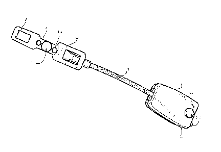
(12) Patent: (11) CA 2995211
(54) English Title: VEHICLE SAFETY DEVICE
(54) French Title: DISPOSITIF DE SECURITE POUR VEHICULE
Status: Deemed Expired
Bibliographic Data
(51) International Patent Classification (IPC):
  • B60R 22/12 (2006.01)
  • B25F 1/00 (2006.01)
  • B60R 22/26 (2006.01)
(72) Inventors :
  • NOGUERA, ANGEL (United States of America)
(73) Owners :
  • ANGEL NOGUERA
(71) Applicants :
  • ANGEL NOGUERA (United States of America)
(74) Agent: GOWLING WLG (CANADA) LLP
(74) Associate agent:
(45) Issued: 2022-07-26
(86) PCT Filing Date: 2016-08-11
(87) Open to Public Inspection: 2017-02-16
Examination requested: 2021-08-09
Availability of licence: N/A
Dedicated to the Public: N/A
(25) Language of filing: English

Patent Cooperation Treaty (PCT): Yes
(86) PCT Filing Number: PCT/US2016/046577
(87) International Publication Number: WO 2017027719
(85) National Entry: 2018-02-08

(30) Application Priority Data:
Application No. Country/Territory Date
62/204,019 (United States of America) 2015-08-12

Abstracts

English Abstract

A seat belt extender comprises a rotatable member having multiple blades of different sizes that engage the receptacle mounted to the vehicle. At the opposite end of the seat belt extender is a receptacle that receives the blade that is connected to the seat belt and/or seat belt and shoulder harness.


French Abstract

Rallonge de ceinture de sécurité comprenant un élément rotatif pourvu de multiples languettes de différentes tailles qui s'emboîtent dans la boucle montée dans le véhicule. Une boucle, à l'extrémité opposée de la rallonge de la ceinture de sécurité, reçoit la languette qui est reliée à la ceinture de sécurité et/ou au harnais.

Claims

Note: Claims are shown in the official language in which they were submitted.

WHAT IS CLAIMED
1. A vehicle safety device, comprising:
a female receptacle constructed and arranged to receive and hold a male end of
a vehicle seat belt;
a construct comprising a first blade constructed and arranged to engage and be
held within a seat belt receptacle of a vehicle, and comprising a second blade
constructed
and arranged to engage and be held within a seat belt receptacle of the
vehicle; and
a flexible linkage that connects the female receptacle and the construct;
wherein the construct is selectively rotatable relative to the flexible
linkage.
2. A vehicle safety device as described in claim 1, further comprising a
locking
mechanism that secures the construct with either the first blade or the second
blade as
selected extending past the flexible linkage.
3. A vehicle safety device as described in claim 1, wherein the first blade
is
constructed and arranged to be held within a seat belt receptacle of a first
configuration
and the second blade is constructed and arranged to be held within a seat belt
receptacle
of a second configuration that is dimensionally different than the seat belt
receptacle of
the first configuration.
4. A vehicle safety device as described in claim 1, wherein the flexible
linkage is
formed of wire cable.
6

5. A vehicle safety device as described in claim 1, wherein the female
receptacle
comprises a light emitter.
6. A vehicle safety device as described in claim 1, wherein the flexible
linkage has a
length of not less than 15 centimeters.
7. A vehicle safety device as described in claim 1, wherein the female
receptacle
comprises a window breaker.
8. A vehicle safety device as described in claim 7, the window breaker
comprising a
base that narrows along its length to form a point, wherein the window breaker
is formed
of hard metal.
9. A vehicle safety device as described in claim 8, wherein the hard metal
comprises
tungsten carbide.
10. A vehicle safety device, comprising:
a female receptacle constructed and arranged to receive and hold a male end of
a vehicle seat belt;
a construct comprising a first blade constructed and arranged to engage and be
held within a seat belt receptacle of a vehicle;
7

a flexible linkage that connects the female receptacle and the construct, the
flexible
linkage having a length of not less than 15 centimeters; and
a second construct comprising the female receptacle and a window breaker, the
window breaker comprising a base that narrows along its length to form a
point, wherein
the window breaker is formed of hard metal.
11. A vehicle safety device as described in claim 10, wherein the flexible
linkage is
formed of wire cable.
12. A vehicle safety device as described in claim 10, wherein the hard
metal comprises
tungsten carbide.
13. A vehicle safety device as described in claim 10, wherein the construct
further
comprises a second blade.
14. A vehicle safety device as described in claim 10, wherein the female
receptacle
comprises a light emitter.
8

Description

Note: Descriptions are shown in the official language in which they were submitted.


CA 02995211 2018-02-08
WO 2017/027719 PCT/US2016/046577
VEHICLE SAFETY DEVICE
FIELD OF THE INVENTION
[001] This invention relates to safety devices for vehicle seat belts.
BACKGROUND OF THE INVENTION
[002] Seat belts are mandatory equipment in all vehicles manufactured and sold
in the
United States and in most other countries. Seat belts are also mandatory in
most airplanes in
current manufacture and seat belts are commonly used in many other vehicles.
[003] Seat belts are characterized by a belt that surrounds the waist of the
wearer
opposite the seat, and frequently, the belt is joined to a shoulder harness.
[004] A flat blade is retained by the belt, with the flat blade usually
having a slidable
engagement with the belt. The flat blade engages a receiver that is mounted in
a sturdy fashion
to the vehicle, sometimes having a pivoting mounting to the vehicle.
[005] In some applications, it is desirable to be able to extend the effective
size or
length of the seat belt. Examples include persons who have a large girth and
pregnant women
who desire or require a longer seat belt. Also, seat belts can be used to
retain articles, rather
than persons, within the seat. The seat belt extender may allow larger items
to be retained by
the seat belt, increasing the safety of transporting such articles.
[006] A seat belt extender is typically an item that is sold and used on an
after-market
basis, and is not supplied as original equipment. The user of the seat belt
extender may own
vehicles produced by more than one manufacturer. Therefore, the blades and
receivers for
each vehicle may be of different sizes.
[007] Window breaking devices for vehicles are useful in emergencies. If a
vehicle
becomes suddenly submerged, electric windows will not work, and water pressure
prevents
doors from opening. Other situations indicate that an exit through a window is
advisable, such
SUBSTITUTE SHEET (RULE 26)

CA 02995211 2018-02-08
WO 2017/027719 PCT/US2016/046577
as when a vehicle that has been in an accident that damages the doors, and
fire or smoke is
present. Tempered glass of the type used in automobiles and trucks is
difficult to break without
an appropriate tool. When a tool is present inside the vehicle, the tool may
not be readily
accessible or the location may not be known to the passenger.
SUMMARY OF THE INVENTION
[008] The present invention is a seat belt extender. The seat belt extender
comprises
a rotatable member having multiple blades of different sizes that engage the
receptacle
mounted to the vehicle. At the opposite end of the seat belt extender is a
receptacle that
receives the blade that is connected to the seat belt and/or seat belt and
shoulder harness. The
seat belt extender comprises a window breaker. The length of the device
provides substantial
force to break a car window during an emergency.
BRIEF DRAWING DESCRIPTION
[009] Figure 1 is a perspective view of a seat belt extender according to an
embodiment of the invention.
[010] Figure 2 is a top plan view of a rotatable member of the invention
comprising
multiple blades.
[011] Figure 3 is a side view of the rotatable member having multiple blades.
[012] Figure 4 is a seat belt extender according to an embodiment of the
invention
having a cover over the structural elements of the device.
[013] Figure 5A demonstrates positioning of a seat belt before use of the
extender
device according to the invention.
[014] Figure 5B demonstrates possible positioning of the seat belt extender of
the
device.
2
SUBSTITUTE SHEET (RULE 26)

CA 02995211 2018-02-08
WO 2017/027719 PCT/US2016/046577
DESCRIPTION OF PREFERRED EMBODIMENTS
[015] Referring to the drawing figures, Figure 1 shows a receptacle 2; a
linkage 10;
and an end assembly 4 comprising opposing blades 6, 8 that rotate relative to
a center axis 12.
[016] The receptacle 2 is universal for most cars and trucks that have seat
belt blades
that are either about 7/8" or about 1" in width. Most vehicles for sale in the
United States have
one of these sizes. The receptacle is constructed and arranged to accept these
sizes of blades.
The receptacle may be formed to accept other sizes according to embodiments of
the invention.
[017] However, there is no universal blade that will fit substantially all
receptacles
found in cars and trucks. Receptacles in many vehicles require a blade of
about 7/8" blade or a
blade of about 1" (as used in General Motors vehicles).
[018] The present invention provides, in a preferred embodiment, opposing
blades
formed as a unit. In one embodiment, one blade 6 is about 7/8" in width, and
the opposite blade
8 is about 1" wide. Other widths may be provided for other applications. The
blades are
rotatably mounted to a base member 26 at approximately the center of the blade
construct. A
pin or axle 12 mounts the blade construct to the base member, while permitting
rotation of the
blade construct.
[019] A blade of the appropriate width chosen by the user is rotated to extend
from the
seat belt extender opposite the linkage 10. The blade 8 is in position for
insertion into the
receptacle of the vehicle as shown in the illustrations.
[020] A secure stop is provided to limit rotation of the blades once the
chosen blade is
in position for insertion into the receptacle. In a preferred embodiment, a
spring biased detent
14 is provided. Opposing voids 16, 18 are provided in the blade construct
opposite the axle 12.
The voids engage the spring biased detent that is mounted to the base member
26.
[021] The base member 16 is securely mounted to the linkage 10. The linkage is
preferred to be flexible, but must be sufficiently strong to meet safety
regulations for seat belts.
In one embodiment, wound stainless steel cable is used as the linkage. The
base member may
3
SUBSTITUTE SHEET (RULE 26)

CA 02995211 2018-02-08
WO 2017/027719 PCT/US2016/046577
be swaged to the cable. The linkage is preferred to be not less than 15 cm. in
length, and is
more preferred to be between 25 and 50 cm. in length for most applications.
[022] The linkage 10 is securely mounted to the receptacle that is positioned
opposite
the blade construct. In a preferred embodiment, the receptacle comprises a
window breaker 20.
The window breaker may be used to break a window of the vehicle in an
emergency. The
protrusion may be a conically shaped hard metal, such as stainless steel, or
more preferably,
tungsten carbide. The conically shaped window breaker may extend from a base
mounted to
the exterior of the receptacle and extend away form the base to form a point
at a free end
thereof.
[023] A cover 22 may be provided for the device. The cover may extend from the
receptacle at one end to the base member at the opposite end, covering the
linkage, and the
blade of the blade construct that is not inserted into the receptacle of the
vehicle. A portion, or
all, of the cover may be split 24 along one side of the cover to permit access
to the remaining
blade, and to permit rotation of the blade construct as described herein. The
cover is preferred
to be resilient, such as formed of a plastic material like polypropylene, and
have shape memory
properties. If split along its length, the cover may be easily removed and
easily replaced to
surround the linkage and some or all of the end assembly 4.
[024] In use, a seat belt blade of the vehicle is inserted into the receptacle
2. The
appropriate blade is rotated into position to extend from an end of the
device, and is locked into
position, such as by engagement of the spring biased detent 14 with the
associated void 18.
The selected blade of the device is inserted into the receptacle of the
vehicle. The seat belt
extender is removed from the vehicle as one would disengage a seat belt blade
from a vehicle's
receptacle, except that both the blade of the device and the receptacle of the
device are
disengaged from the vehicle. Optionally, the blade of the vehicle may remain
in the receptacle,
with the seat belt extender remaining in position for use in the vehicle.
4
SUBSTITUTE SHEET (RULE 26)

CA 02995211 2018-02-08
WO 2017/027719 PCT/US2016/046577
[025] The additional length provided by the devices may elevate the receptacle
2. The
resulting attachment point may bring the attachment point closer to the center
of mass of a
wearer 30, as demonstrated by Figures 5A and 5B. It is believed the wearer may
be subjected
to less torque in the event of a sudden stop, perhaps which may reduce about
the centerline 34
resulting in less rotation of the spine. It is also believed that forces
against the seat belt during a
sudden stop are more evenly distributed to each of the attachment points 32 of
the seat belt.
[026] The embodiment that incorporates the window breaker 20 may be used by
removing the seat belt extender from its engagement with the vehicle. For
example, if the
vehicle is overwhelmed by water, the seat belt extender may be removed and
used to break a
window. The length of the linkage and the flexibility of the linkage 10
provide a whiplash effect
that provides additional velocity for the window breaker over hammer type
devices. The
increased velocity of the window breaker assists in breaking a window.
[027] The position of the window breaker on the seat belt construct makes the
window
breaker readily available in the event of an occurrence where time is of the
essence, such as
when a vehicle interior is filling with smoke or water, or is on fire. A user
need not hunt through
the interior of the car for a tool to break a window. The invention provides a
window breaker
that is readily available. Removal of the seat belt is necessary for exiting
in any event so that
only one additional step is necessary, which is separating the seat belt
extender from the stock
vehicle seat belt.
[028] The housing of the receptacle may incorporate a flashlight, such as an
LED
flashlight 36, and batteries. A switch 38 may be provided to actuate the
light, and the device
used as a flashlight after removal from the vehicle. One or more LEDs may be
positioned on
either side of the receptacle that receives the blade in some embodiments of
the invention.
The flashlight may be waterproof. Light is provided by the device
independently of the vehicle's
electrical system, which may not function in the event of an accident.
SUBSTITUTE SHEET (RULE 26)

Representative Drawing
A single figure which represents the drawing illustrating the invention.
Administrative Status

2024-08-01:As part of the Next Generation Patents (NGP) transition, the Canadian Patents Database (CPD) now contains a more detailed Event History, which replicates the Event Log of our new back-office solution.

Please note that "Inactive:" events refers to events no longer in use in our new back-office solution.

For a clearer understanding of the status of the application/patent presented on this page, the site Disclaimer , as well as the definitions for Patent , Event History , Maintenance Fee  and Payment History  should be consulted.

Event History

Description Date
Letter Sent 2024-02-12
Letter Sent 2023-08-11
Inactive: Grant downloaded 2022-07-27
Grant by Issuance 2022-07-26
Letter Sent 2022-07-26
Inactive: Cover page published 2022-07-25
Pre-grant 2022-06-07
Inactive: Final fee received 2022-06-07
Notice of Allowance is Issued 2022-02-07
Letter Sent 2022-02-07
Notice of Allowance is Issued 2022-02-07
Inactive: Approved for allowance (AFA) 2022-02-04
Inactive: Q2 passed 2022-02-04
Advanced Examination Determined Compliant - PPH 2022-01-04
Amendment Received - Voluntary Amendment 2022-01-04
Advanced Examination Requested - PPH 2022-01-04
Letter Sent 2021-08-19
Request for Examination Received 2021-08-09
Request for Examination Requirements Determined Compliant 2021-08-09
All Requirements for Examination Determined Compliant 2021-08-09
Common Representative Appointed 2019-10-30
Amendment Received - Voluntary Amendment 2018-06-26
Change of Address or Method of Correspondence Request Received 2018-06-11
Inactive: Cover page published 2018-04-05
Inactive: First IPC assigned 2018-03-05
Inactive: Notice - National entry - No RFE 2018-02-26
Inactive: IPC assigned 2018-02-21
Application Received - PCT 2018-02-21
National Entry Requirements Determined Compliant 2018-02-08
Application Published (Open to Public Inspection) 2017-02-16

Abandonment History

There is no abandonment history.

Maintenance Fee

The last payment was received on 2021-08-06

Note : If the full payment has not been received on or before the date indicated, a further fee may be required which may be one of the following

  • the reinstatement fee;
  • the late payment fee; or
  • additional fee to reverse deemed expiry.

Please refer to the CIPO Patent Fees web page to see all current fee amounts.

Fee History

Fee Type Anniversary Year Due Date Paid Date
Basic national fee - standard 2018-02-08
MF (application, 2nd anniv.) - standard 02 2018-08-13 2018-05-24
MF (application, 3rd anniv.) - standard 03 2019-08-12 2019-07-22
MF (application, 4th anniv.) - standard 04 2020-08-11 2020-07-08
MF (application, 5th anniv.) - standard 05 2021-08-11 2021-08-06
Request for examination - standard 2021-08-11 2021-08-09
Final fee - standard 2022-06-07 2022-06-07
MF (patent, 6th anniv.) - standard 2022-08-11 2022-08-05
Owners on Record

Note: Records showing the ownership history in alphabetical order.

Current Owners on Record
ANGEL NOGUERA
Past Owners on Record
None
Past Owners that do not appear in the "Owners on Record" listing will appear in other documentation within the application.
Documents

To view selected files, please enter reCAPTCHA code :


To view images, click a link in the Document Description column. To download the documents, select one or more checkboxes in the first column and then click the "Download Selected in PDF format (Zip Archive)" or the "Download Selected as Single PDF" button.

List of published and non-published patent-specific documents on the CPD .

If you have any difficulty accessing content, you can call the Client Service Centre at 1-866-997-1936 or send them an e-mail at CIPO Client Service Centre.


Document
Description 
Date
(yyyy-mm-dd) 
Number of pages   Size of Image (KB) 
Cover Page 2022-07-04 1 36
Description 2018-02-08 5 234
Drawings 2018-02-08 5 76
Abstract 2018-02-08 1 54
Claims 2018-02-08 2 57
Representative drawing 2018-02-08 1 15
Cover Page 2018-03-29 1 36
Claims 2018-06-26 4 114
Claims 2022-01-04 3 75
Representative drawing 2022-07-04 1 8
Notice of National Entry 2018-02-26 1 193
Reminder of maintenance fee due 2018-04-12 1 113
Courtesy - Patent Term Deemed Expired 2024-03-25 1 551
Courtesy - Acknowledgement of Request for Examination 2021-08-19 1 423
Commissioner's Notice - Application Found Allowable 2022-02-07 1 570
Commissioner's Notice - Maintenance Fee for a Patent Not Paid 2023-09-22 1 540
Electronic Grant Certificate 2022-07-26 1 2,526
National entry request 2018-02-08 2 66
International search report 2018-02-08 2 78
Amendment / response to report 2018-06-26 6 151
Request for examination 2021-08-09 3 77
PPH request / Amendment 2022-01-04 22 638
PPH supporting documents 2022-01-04 3 176
Final fee 2022-06-07 3 77